1. Introduction
Most compressors currently use the radial inlet as the upstream component [
1]. As the radial inlet transports working fluids from the pipelines to the impeller inlet, it should provide a uniform flow field for the impeller to guarantee the compressor good performance. Due to the complex configuration of the radial inlet, the flow field in it shows complicated three-dimensional characteristics, which means that a uniform flow field can barely be obtained in the radial inlet, and it harms the performance of the compressor [
2]. Generally, the radial inlet causes a 1% to 4% and a 2% to 4% decrease in efficiency and total pressure of the compressor, respectively, compared with the axial flow inlet [
3,
4]. Therefore, researchers investigating the flow characteristic of the radial inlet through experiments and numerical simulations is meaningful for the compressor.
Tan et al. [
5] reviewed the radial inlet from the internal flow in the radial inlet and its effects on the compressor performance [
6], and summarized the design of the structure and optimum method in the radial inlet [
7]. Using three-hole probes, Flathers et al. [
8] measured the flow parameter distribution at the exit of the radial inlet and compared the experiment and simulation. Han et al. [
9] measured the flow in the radial inlet and observed the flow loss and distortions caused by flow separations and vortices. Through different conditions, Zhang et al. [
10] analyzed the relationship between the bent torsional methods and the compressor performance based on the experiments. MacManus et al. [
11] and Yamada et al. [
12] respectively investigated the effects of upstream and swirling distortions based on S-duct and bent pipes in the single-stage centrifugal compressor and found that the geometry greatly influenced the downstream flow field.
Based on the development of technology, the optimization methods are suitable for engineering design. Wu et al. [
13] simplified the structure of the radial inlet by parameterized design model analysis, which improved the precision and efficiency of the radial inlet design. With the assistance of the computational fluid dynamics technique, an optimization approach for the radial inlet design of the meridian plane was developed by Chen [
14] to obtain a 1.26% improvement in the polytropic efficiency. Yagi et al. [
15] optimized the radial inlet structure by proposing an optimization method to increase the efficiency by a new design parameter. The parameter had a significant impact on the total pressure loss and the circumferential non-uniformity in the radial inlet.
In addition, adding the guide vane could improve the flow field and weaken the negative impact of the radial inlet [
16]. Wang et al. [
17] added the vanes in the radial inlet, which resulted in the flow loss increasing and the flow distortion decreasing. Through optimizing the profile of vanes in the radial inlet, the flow separation loss was further reduced, which increased the efficiency of the compressor. Han et al. [
18] added the guide vanes in the radial inlet and increased the efficiency by 4.97% over different operating conditions for the compressor.
Most of the literature indicates that the radial inlet has a significant effect on the safety of the downstream impeller. By reviewing the unsteady aerodynamic loads in the centrifugal compressor, Wang et al. [
19] considered that the flow characteristic in the radial inlet is an essential factor for analyzing the safety of the impeller that cannot be ignored. During the compressor operation, Han et al. [
20] found that the radial inlet excited aerodynamic load on the impeller, but the impeller had a slight effect on the flow field of upstream the impeller, i.e., in the radial inlet. In the radial inlet, Xin et al. [
21] added the guide vanes to protect the impeller by providing a uniform flow field and decreasing the aerodynamic load on the impeller at the machine rotation frequency.
Setting guide vanes in the radial inlet is beneficial for improving the flow field. However, the guide vane wake generates one more aerodynamic load on the impeller due to the rotor–stator interaction (RSI) [
22]. Furthermore, hydrogen as the working fluid can easily raise the hydrogen embrittlement in the compressor. Therefore, the RSI and hydrogen embrittlement threaten hydrogen compressor safety. The trailing edge blowing (TEB) proposed by Park and Cimbala [
23] is an active control method to reduce the effect of wake and RSI. According to the wake characteristics, the wakes can divide into four categories: the pure wake, the weak wake, the momentumless wake, and the jet.
Wu et al. [
24] measured the mean velocity profiles of the wake and indicated that the momentumless wake made the inlet flow of the rotor more uniform and improved the inlet flow angle of the rotor. By adding an extra 2% flow rate for TEB, Lewis et al. [
25] decreased about 43% of the amplitude at the blade passing frequency in the Francis turbine. Based on the centrifugal compressor with TEB on the guide vanes, Xin et al. [
26] analyzed the flow field and aerodynamic load on the impeller. When obtaining the momentumless wake, the aerodynamic loads on the impeller had reduced significantly. Combined with the TEB method, Xin et al. [
27] investigated the effect of the radial inlet guide vane. The results showed that the TEB reduced the wake intensity and decreased the aerodynamic load, which ensured a smooth operation and provided a long lifetime for the compressor. Moreover, the passive control method was suitable for reducing the total pressure loss and decreasing the wake intensity in turbomachinery. Eberlinc et al. [
28] set the slot in the rotor for the axial fan and led the fluid flow from the root to the tip by centrifugal force. This performance improved the flow field near the tip region, decreased the boundary layer separation, and increased the fan efficiency. Based on a cavity for flow recirculation, Cravero et al. [
29] adopted the ported shroud on the centrifugal compressor to avoid blade passage blocking in near-surge conditions. Xin et al. [
30] added a two-slot configuration in the inlet guide vane of the compressor, and the results showed that the slot changed the wake distribution under different operation conditions [
31]. Under winter conditions, i.e., the angle of 38.6°, the slot produced a nearly 13% reduction of the amplitude of the impeller passing frequency at the leading edge.
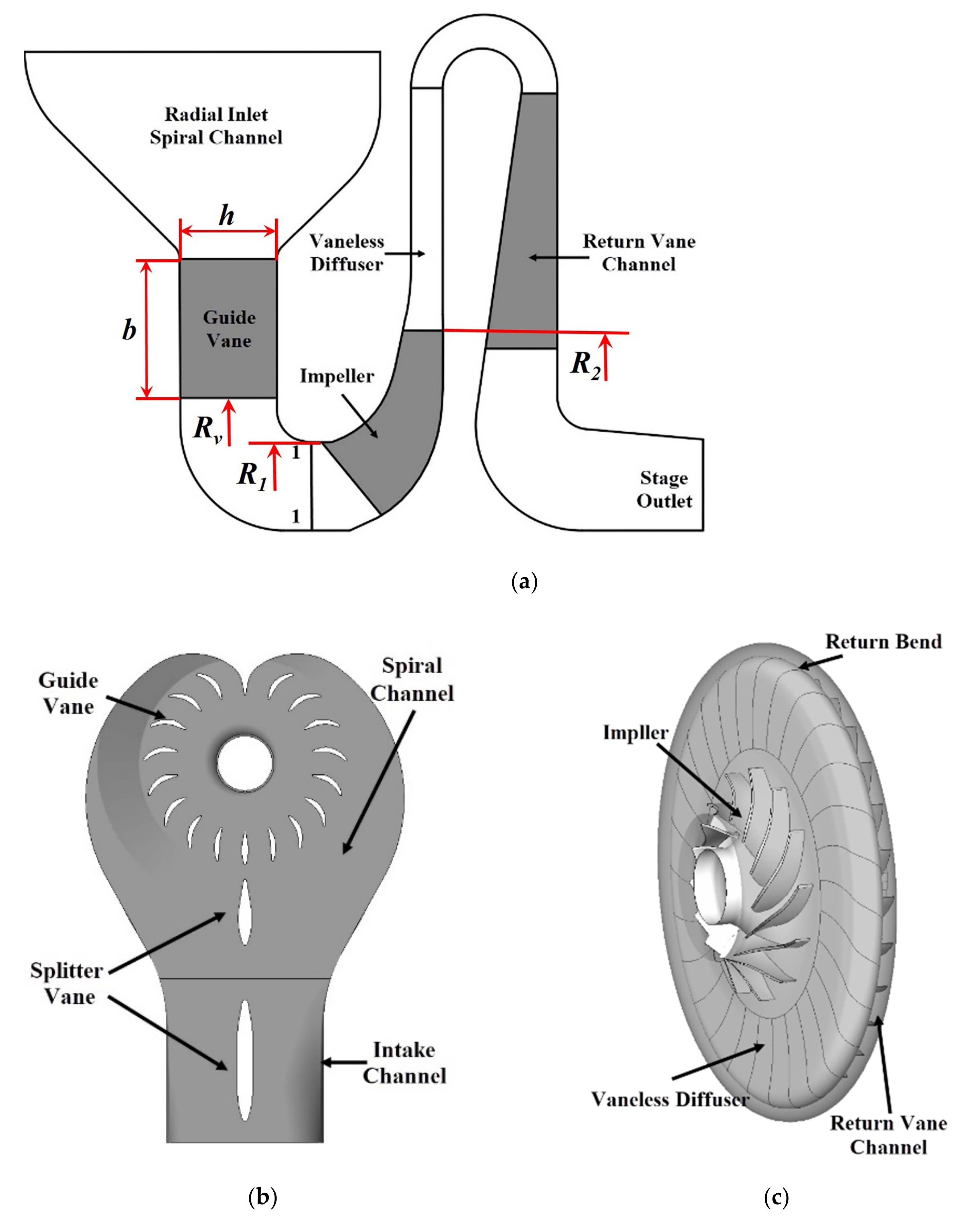
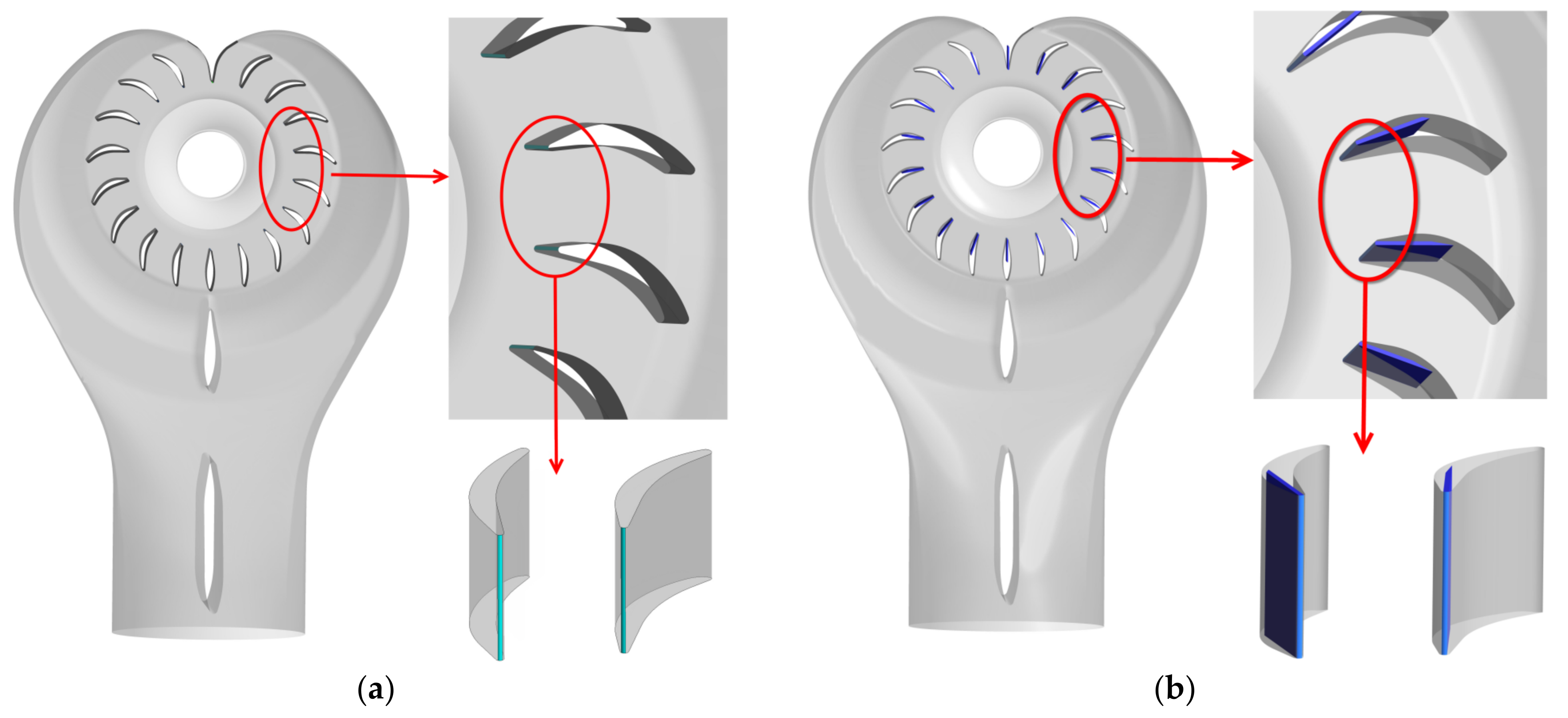
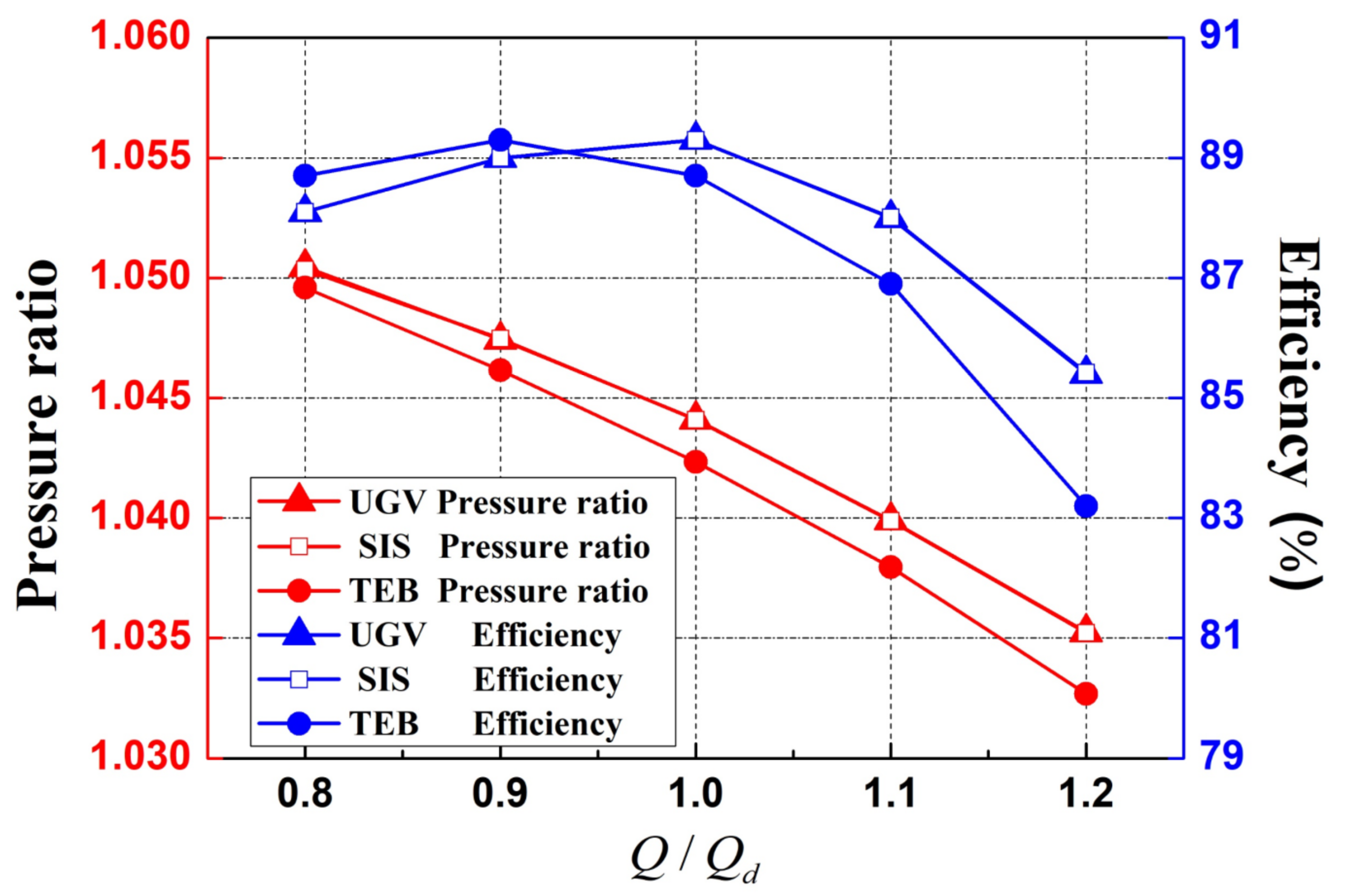
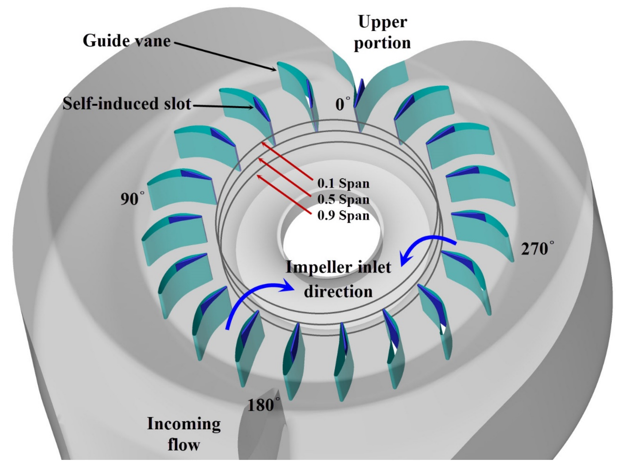
As the TEB method needs extra power from the outside of the compressor, this study adopted a passive control method, which employs the self-induced slot (SIS) on the guide vane. The hydrogen compressor with radial inlet was engaged in this paper to evaluate the effects of the SIS method on compressor performance and aerodynamic load on the impeller. Meanwhile, the TEB method was used for comparison in this study. Through the analysis using numerical simulation, the effects of the SIS method on the compressor performance, flow field in the radial inlet, and the aerodynamic load on the impeller were investigated.
The organization of this paper is as follows. The second section describes the hydrogen compressor and the computational consideration, which includes the scheme of TEB and SIS methods. The aerodynamic load and the flow field in TEB and SIS models are analyzed in the third section compared with the UGV model. Lastly, the fourth section provides some conclusions.


