Article

Hybrid Modeling of Deformable Linear Objects for Their Cooperative Transportation by Teams of Quadrotors

1
Faculty of Engineering of Gipuzkoa, University of the Basque Country, 20018 San Sebastian, Spain
2
Faculty of Engineering of Vitoria, University of the Basque Country, 01006 Vitoria, Spain
3
Faculty of Computer Science, University of the Basque Country, 20018 San Sebastian, Spain
*
Author to whom correspondence should be addressed.
Appl. Sci. 2022, 12(10), 5253; https://doi.org/10.3390/app12105253
Submission received: 9 March 2022 / Revised: 16 May 2022 / Accepted: 17 May 2022 / Published: 23 May 2022

Abstract

:
This paper deals with the control of a team of unmanned air vehicles (UAVs), specifically quadrotors, for which their mission is the transportation of a deformable linear object (DLO), i.e., a cable, hose or similar object in quasi-stationary state, while cruising towards destination. Such missions have strong industrial applications in the transportation of hoses or power cables to specific locations, such as the emergency power or water supply in hazard situations such as fires or earthquake damaged structures. This control must be robust to withstand strong and sudden wind disturbances and remain stable after aggressive maneuvers, i.e., sharp changes of direction or acceleration. To cope with these, we have previously developed the online adaptation of the proportional derivative (PD) controllers of the quadrotors thrusters, implemented by a fuzzy logic rule system that experienced adaptation by a stochastic gradient rule. However, sagging conditions appearing when the transporting drones are too close or too far away induce singularities in the DLO catenary models, breaking apart the control system. The paper’s main contribution is the formulation of the hybrid selective model of the DLO sections as either catenaries or parabolas, which allows us to overcome these sagging conditions. We provide the specific decision rule to shift between DLO models. Simulation results demonstrate the performance of the proposed approach under stringent conditions.

1. Introduction

Since 1970s, towed cable systems have been analyzed for various applications of payload aerial transportation including payload delivery, kites, aerial refueling systems, brick transportation and rescue missions [1]. Recently, unmanned aerial vehicles (UAVs) capabilities for the transportation and manipulation of objects have caught the attention of researchers for the transportation of diverse types of objects, for inspection and maintenance of industrial elements and surfaces and for other industrial- and emergency-related applications [2,3,4]. Researchers have invested a big effort in last years in developing different control models, vision systems and grasping or contact mechanisms in order to cope with all the difficulties that these systems find [5]. In particular, multi-rotors have become increasingly affordable for e by industries for delivery and inspection, with some start-ups becoming successful companies. Cooperative teams of quadrotors have great potential for some applications such as suspended object transportation [6,7].
More specifically, cooperative tasks of quadrotor transportation of deformable linear objects (DLO) (i.e., cables or hoses) is being proved to be very useful in emergencies and in hardly accessible areas [8], fire extinction [9], windmill turbine cleaning [10], liquid spraying [11,12] or transportation of payloads suspended from cables attached to the UAVs [13,14]. In the latter case, most e approaches assume that cables are rigid links connecting the UAV and the payload without intrinsic dynamics. However, in the other cases, accurate DLO geometrical and dynamical modeling is essential in order to achieve precise and robust control of the entire system encompassing the DLO and the transporting quadrotors. Recent works deal with DLO modeling by catenaries [13], while others decompose the DLO into a sequence of connected rigid links [15] in order to build up the control system coping with DLO transportation and manipulation. Catenary modeling has been applied to design proportional derivative (PD) controllers [16] that achieve the task of DLO transportation by a team of quadrotors [17,18]; however, catenary models cannot cope with aggressive maneuvers, involving sharp changes in direction and an acceleration of the drones desired trajectories. Sudden changes in the relative positions of the drones can abruptly change the shape of the DLO segments pushing their geometrical models off limits. Such sagging conditions appear due to distances that are too short or too long between the drones, making the DLO catenary model fall into singularities so that the entire control system fails. Alternatively, the parabola may be used as an approximation for the catenary [19,20,21] that does not suffer from sagging conditions.
In previous studies [18], we have developed the online adaptation of a fuzzy logic rule system that sets the parameters of the drone PD controllers. This adaptation is carried out independently for each drone in the team transporting the DLO. Figure 1 presents an overall block diagram of the system. We have shown the effectiveness of the fuzzy logic adaptive control system to achieve some aggressive maneuvers with sharp direction changes, compromising UAV team formations during DLO transportation. The enhanced control system permits UAVs to follow the mission path and to retain a distance between them in a stable and smooth manner.
The main contribution of this paper is as follows: We present a hybrid modeling system switching between catenary and parabola models of DLO segments hanging between pairs of drones in order to achieve robust control in the presence of wind disturbances and aggressive maneuvers and overcoming sagging conditions. We provide the decision threshold based on the relation between the distance among drones and the actual length of the DLO.
The article structure is as follows: Section 2, reviews related works in the literature. Section 3 presents the hybrid DLO modeling switching between the catenary and parabola. Section 4 presents the follow-the-leader formation of the quadrotor team that will be followed in the experiment. Section 5 describes the quadrotor control system, including the novel online adaptive PD tuning based on a fuzzy adaptive gradient descent rule. Section 6 describes the experimental settings. Section 7 reports the results that demonstrate the effectiveness of the proposed control system. Finally, Section 8 provides our conclusions and lines of future work.

2. Related Works

Table 1 offers a summary categorization of the relevant literature. Discrete DLO models tackle the problem by breaking down the structure into a number of rigid rod elements of finite length, which can be physically simulated as pendulums, curve segments or by a network of masses and springs, so called lumped-mass models. These models require the representation of forces and moments at each element so that it is possible to model the motion of each and all of them. A study comparing several modeling methods concluded that the lumped-mass representation is the most versatile method, despite the large amount of computational resources required for its implementation [22]. Alternatively, some approaches propose the modeling of the DLO as a chain of rigid links allowing the differentially flat control [23] of the team carrying the DLO transportation under quasi-stationary conditions [15]. Nevertheless, comparative studies on cable structure modeling show the superior numerical efficiency of catenaries for the study of different force situations, vibrations and torsions [24,25,26].
Catenaries are widely accepted as accurate cable models, for instance, in mooring cable simulations [32,36,39], and in the design of civil cable structures [28,50]. Continuous cable modeling by catenaries is more accurate and less computationally demanding [30] than discretization approaches. The cable modeling by a catenary relies on the following assumptions and simplifications [51]: The mass per unit length of cable is constant, there is no torsion, the cable cannot increase its length and the cross-section of the cable is much smaller than the longitudinal dimension, corresponding to a 2D solid at any time, hence resulting in the general term of deformable linear object (DLO) that we use in this paper. In some studies, the geometry of cable segments has been approximated by parabolas [35] and other second degree polynomials [24], which allow faster computations and are robust enough to accurately model the sagged cables [49]. Following this background, we propose our hybrid DLO modeling methods, as discussed below.
Tethered UAVs, also known as taut tethers, are a special case where the UAV has its center of the mass attached to the global coordinate frame origin by a DLO, which is a tense cable with negligible mass. Most research studies consider that, in this configuration, the cables are rigid links. Different variations and evolutions of this model have been proposed in the last years for different tasks in ground robotics or ship operations [34,41,43,52]. Catenaries usage for tethered UAVs have not been deeply studied despite early promising results [29,46].
Table 1. Summary comparison of DLO related research. DvC = Discrete versus continuous model.
Ref.YearDvCParadigmApplications
[27]1971continuouscatenarycable towed by aircraft
[22]1973bothAnalytical methods (survey)Ocean Science
[28]1981continuouscatenarycable structures
[29]1995continuouscatenarycable towed by aircraft
[30]1999bothcatenary vs. rod elements
[31]2000continouscatenaryunderwater towing
[32]2001continuouscatenaryocean sciences, mooring
[33]2001continuouscatenaryunderwater towing
[24]2006continuouscatenarydesigns of nets of cables
[34]2007continuoysrigid linktethered UAV
[35]2008continuousparabolacable structures
[36]2008continuouscatenaryocean sciences, mooring
[37]2009continuousrigid linkcooperating UAV payload transport
[38]2010continuousrigid linkcooperating UAV payload transport
[39]2012continuouscatenarycable-driven parallel robot
[40]2012continuousrigid linkcooperating UAV payload transport
[41]2013continuousrigid linktethered UAV
[42]2013continuouscatenarycable-driven parallel robot
[43]2015continousrigid linktethered survillance UAV
[44]2015discreteseries of rigid linkscooperating UAV payload transport
[18,45]2015, 2017continuouscatenaryDLO transportation by n 2 UAVs
[46]2016continuouscatenarytethered UAV
[47]2017continuouscatenarytethered UAVs
[48]2017continuouscatenarycable transportation by 2 UAVs
[25]2018continuouscatenarysuspension bridges
[26]2018continuouscatenarysuspension bridges
[49]2018continuouscatenary and parabolacable vibrations
[15]2020discretechain of rigid linkshose transportation by 2 UAVs
[13]2021continuouscatenarycable transportation by 2 UAVs
For UAV transportation of payloads hanging from a cable [13], cable dynamics modeling is a key factor for understanding the system’s dynamics and permit the computation of forces exerted on the quadrotor, where the motion of the entire cable is represented as a continuous structure with appropriate boundary conditions. Their main advantage is that the simultaneous consideration of each point in the material permits the calculus of more accurate cable dynamics [27,29,31,33].
In the cooperative transportation of a load by a team of UAVs, the cables are often modeled as a rigid link [37,38]. Cooperative aerial towing problem is similar to the problem of controlling cable-actuated parallel manipulators in three dimensions. In these systems, the variation of the lengths of cable attachments determines the payload orientation and position. Following this line of research, [44] modeled the system as a serially connected links system for the cooperative transportation and orientation of a rigid two-dimensional payload. The transportation of a DLO attached by cables to the UAVs under severe dynamic limitations and quasi-static conditions was also achieved [40].
In previous studies dealing with the cooperative transportation of DLOs by teams of UAVs, DLO sections were modeled as catenaries in an equiload vertical configuration [18,45]. Additional sources confirm that catenaries are a good modeling alternative for the cooperative aerial transportation of DLOs [13], including visual servoing approaches [47], and collision avoidance [39,48]. However, catenary curves are hyperbolic functions that suffer from numerical singularities, which may lead the control system to collapse when the distances between quadrotors are too short or too large relative to the DLO’s section length due to cable sagging [42]. This situation occurs when the team of quadrotors must perform aggressive maneuvers consisting of sudden sharp changes of direction and/or accelerations. In order to deal with these extreme conditions, we propose the hybrid modeling of DLOs that shifts between catenary and parabola models according to the system state.
Finally, the transportation of a cable by pairs of UAVs has been proposed for the grasping and transportation of objects featuring some kind of hook, such as umbrellas [13]. After the hooking maneuver, the shape of the cable can be modeled by straight sections, and the entire system can be treated as cooperative payload transportation from suspended cables.
During recent years, there has been a large effort devoted to the development of a flexible dynamic model of low computational cost of DLO payloads, because, despite their passive nature, payload configurations might affect the performance of the control of the robot carrying out the transportation task. Taut cables modeled as a metal bar are valid only for a small spectrum of applications. Discrete cable modeling remains computationally too costly. Catenary models emerged as a possible representation model with promising results and have already been tested in simulations of simple robotic experiments. In order to capture the best possible reality, by taking into account the bibliography on cable structures [22,24,30,53], we propose a hybrid catenary–parabola cable model so that the control systems of teams of drones for aerial transportation of long cables can cope with demanding maneuvers. As far as the authors know, this type of switching model has never been applied in cable transportation tasks with quadrotors.

3. Parabola–Catenary Hybrid DLO Geometrical Model

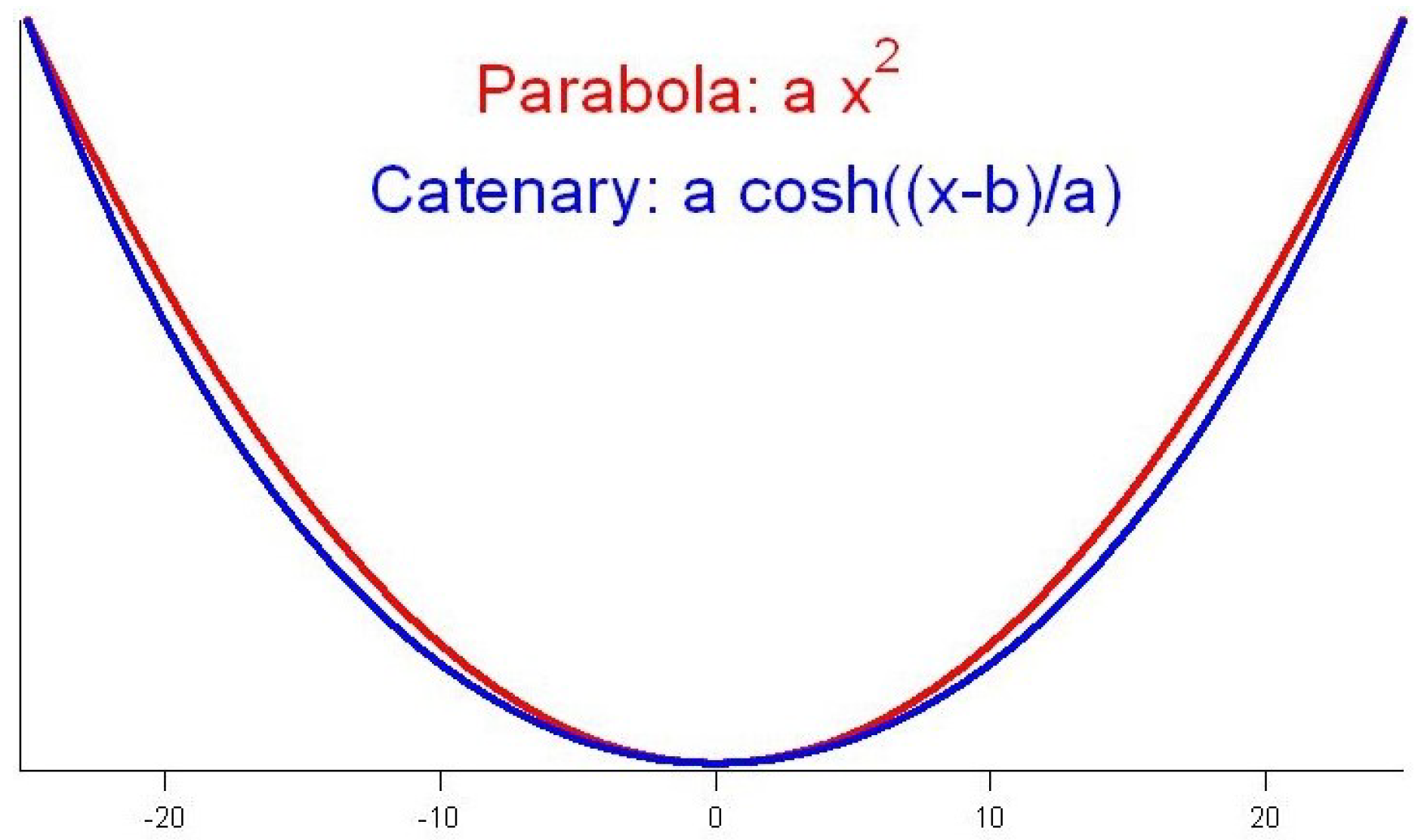
The catenary equation y = a cosh x a is derived from well-known fundamental equations of applied mechanics as the shape that takes a flexible but non-elastic DLO hanging from two extremes under its own weight. Parabola equation y = a x 2 has been used as a surrogate geometric model approximation of the shape of hanging cables for both static or kinematics analysis [30,54,55], because it is more robust to extreme conditions that induce singularities in the catenary equation. In general applications, such as modeling the dynamic behavior of cables or bridge structures, the dynamic simulations of objects modeled alternatively as a parabola or the catenary are very similar, except under very heavy payloads where the differences among these functions might introduce substantial differences on analysis results [24]. Moreover, the lower computational cost of a parabola is another reason for its use in the mathematical modeling of cables [25]. In the case of robotics, this simplification has been contested in some applications [47]. Figure 2 visualizes the approximation of a catenary by a parabola, which may be good enough for some applications [55,56,57,58], especially in the development of cable-driven robots [59].
This article proposes a hybrid between catenary and parabola geometric models for a DLO section hanging between two drones. Automated switching from one model to the other occurs when the Euclidean distance between the drones is too short relative to the actual length of the DLO section. In this situation, the catenary is no longer a good approximation to the shape of the DLO. Heuristically, we have set the threshold for the shift between models at d < L / 3 , where L is the length of the DLO section and d the Euclidean horizontal distance between the drones supporting it. In drone team operation modeling, there are some previous studies on hybrid modeling for control strategies and their formation [60,61,62], but there are no previous studies on hybrid payload modeling.

4. Quadrotor Team Formation Strategy

The quadrotor team transporting the DLO is a follow-the-leader column platoon formation [63] that offers advantages for obstacle avoidance and needs only the specification of the trajectory of the leader to guide the entire team. In aerial transport, this configuration represents a novelty, as most of the published research studies study the collaborative transportation of a heavy load using different approaches to calculate the payload’s position relative to the the quadrotors at any moment, such as the Udwadia–Kalaba method for modeling [6] focused on the estimation of the position of each UAV with respect to the payload in a dynamic equation minimization method. Other studies’ use geometric criteria for calculating the UAVs’ desired position to accomplish the task. For instance, ref. [64] sets the formation with Delaunay triangles, and [65] uses vectorial conditions.
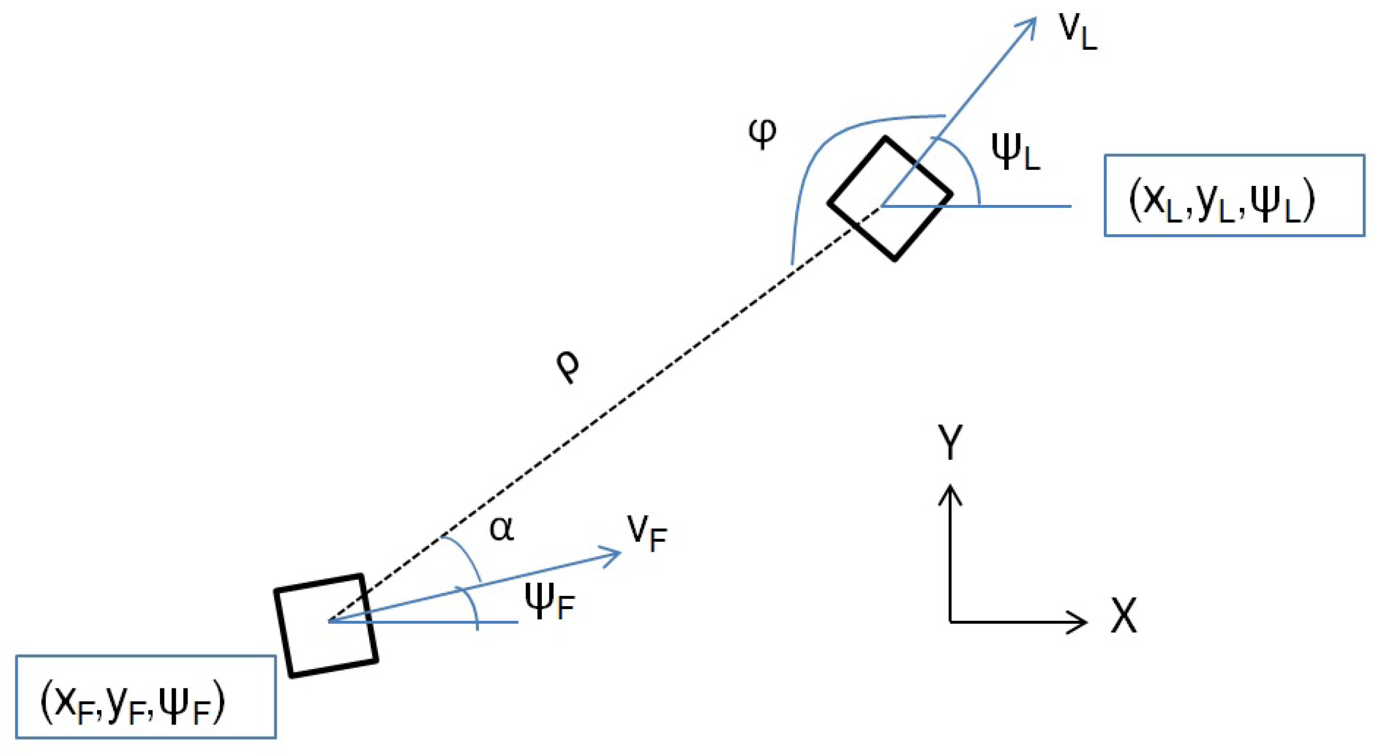
Our approach is inspired in ground robotics [63], adding the extra constraint of maintaining a horizontal Euclidean distance between robots. Orientation and position of each robot are calculated at each moment. The graphical representation of the team configuration over the (X, Y) plane can be seen in Figure 3, where ρ corresponds to the desired distance between robots, and the L and F subindices denote the leader’s and follower’s variables, respectively. Vectors V L and V F are the motion directions of the leader and follower drones, respectively.
Finally, the equations for the position and orientation of the follower UAV relative to the position of the leader UAV [64,66], are as follows.
x F = x L ρ cos ( α + ψ F ) y F = y L + ρ sin ( α + ψ F ) ψ F = φ + ψ L π .

5. System Control

The control system of each quadrotor in the team is composed of an inner and outer loop with proportional derivative (PD) controllers for each degree of freedom. Figure 4 depicts the structure of the system. The inner control loop is in charge of controlling the attitude of the quadrotor by providing rotor commands to achieve desired attitude angles. The outer control loop is in charge of following the desired trajectory by providing the desired attitude angles to the inner control loop. Tuning of the controller parameters by an offline Particle Swarm Optimization algorithm achieved the vertical equiload configuration in the inner loop [17,45] minimizing the final height adjustment overshot and proving to be a scalable system.

Online Adaptation of PD Controllers

Offline tuning of the PD controllers [17] in the outer loop is unable to cope with aggressive maneuvers, such as short radius curves and sharp changes of direction, and neither provides adaptations to different lengths and weights of DLOs. Therefore, we proposed [18] and their online adaptive tuning following an Adaptive Fuzzy Modulation (AFM) approach, combining a gradient descent adaptation rule and a fuzzy membership function activation [67,68]. The membership functions act on the PD controller parameters if a fuzzy logic expression is satisfied, following the Takagi–Sugeno controller design paradigm [69].
The perceived error P e (cf. Equation (2)) measures the relative error between the real position of the UAV Y r e a l and its reference Y r e f at each moment.
P e = Y r e f Y r e a l Y r e f · 100 ,
The proposed fuzzy tuning rules contemplate four error conditions dependent on P e value modeled by corresponding four triangle-shaped membership functions μ i P e i = 1 4 , for which its membership supports are provided by the following.
D μ 1 = 2 , 9 , D μ 2 = 1 , 5 , D μ 3 = 1 , 5 , D μ 4 = 4 , 9 .
The adaptation of parameter K p is modulated by functions μ 1 P e t and μ 4 P e t through Equation (4), while the adaptation of parameter K d is modulated by functions μ 2 P e t and μ 3 P e t with Equation (5):
K p t + 1 = K p t + α e ( t ) μ 1 P e t + μ 4 P e t
K d ( t + 1 ) = K d t + α e ( t ) μ 2 P e t + μ 3 P e t
where α is the adaptation factor, which takes a constant value between 0 and 1 during the entire experiment. The e ( t ) functions compute the instantaneous error relative to the desired values θ d and ϕ d of the angles that determine the motion in the XY plane. The online adaptation Equations (4) and (5) follow a stochastic gradient descent algorithm The convergence of the continuously adaptive process of the fuzzy logic control approach has been proven [18].

6. Experiments

We have carried out three computational simulation experiments that require a team of three quadrotors transporting a DLO attached to them in a follow-the-leader strategy, where followers try to mimic the motion of the leader, i.e., following parallel paths to the one of the leader trying to preserve the distance among quadrotors. In both experimental simulations, time is discretized in steps of 0.1 s, the DLO is modeled by the catenary-parabola approximation and we apply a fuzzy logic approach for the adaptive tuning of the PD controller. Both experiments feature sharp path changes that were unmanageable with previous versions of the controller [17].
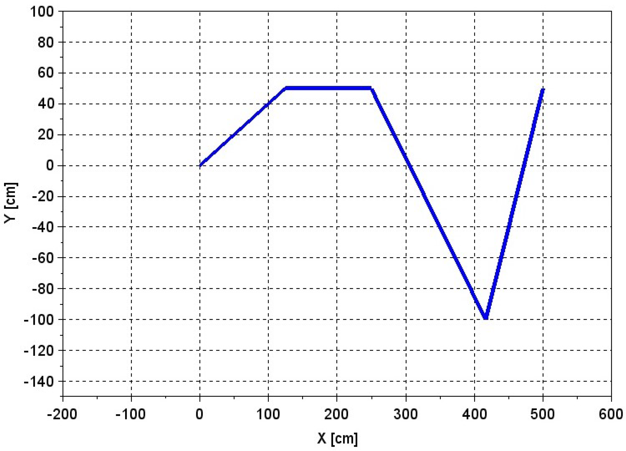
Experiment 1: In this experiment, the nominal path set for the leader quadrotor has sudden changes of direction, as shown in Figure 5. The objective of the experiment is to check whether the drone team’s formation remains stable and is able to cope with the different path corners, particularly with the sharp angle located at x = 400 cm. For the experiment, both with and without wind disturbance conditions in the X direction are used to model the following dynamic equation d ( t ) = 5 + 5 sin ( π 2 t ) .
Experiment 2: In this experiment, the three quadrotors transport the DLO in a straight line path. When the leader drone has traversed a distance of x = 350 cm, it suffers a sudden lateral disturbance consisting of a push displacing it 80 cm in the Y positive direction, as shown in Figure 6. The experiment aims to observe how the leader and followers recover the nominal path after the disturbance.
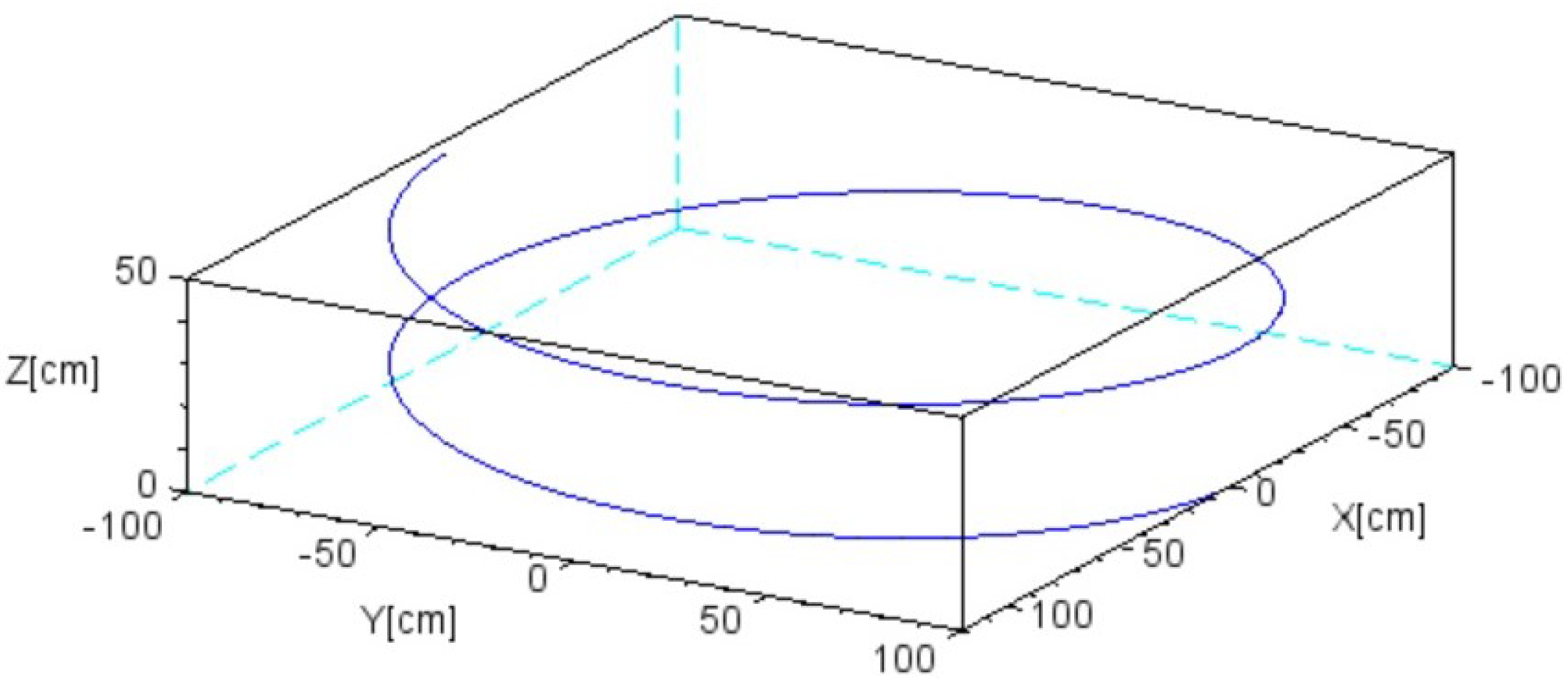
Experiment 3: Now, the three quadrotors must follow a spiral 3D ascending path specified by x = 100 sin ( t ) , y = 100 cos ( t ) , z = 5 ( t ) , with t = [ 0 : 3 π ] , as seen in Figure 7. This test aims to check the capacity of the drones control system to cope with the three direction paths at the same time, with no-wind conditions, and considering only the hybrid DLO model of catenary and parabola. The leader drone’s starting position is at ( 0 , 0 , 0 ) .
In the three experiments, the initial distance in the horizontal axis between drones at the extremes and the central drone is the same and is set as ρ d = 70 cm. Moreover, in order to ensure balanced energy consumption, the system is in equiload conditions [18,45]. As a consequence, no further correction of altitude is applied, although the horizontal Euclidean distance between robots might change. In platoon formation, the maximum vertical thrust was limited for each quadrotor to 20 N following standard hardware specifications. The length of the catenaries was set to L 0 = 240 cm; the mass density of the DLO was set to w = 0.005 [kg/cm]. For online fuzzy tuning of the PD controller, the adaptation factor was set to α = 0.5 . Dynamic parameters of each quadrotor appear in Table 2. We set the initial PD parameter values as follows: K p x = K p y = 0.22 ; K d x = K d y = 0.76 .
Experiments have been coded in house in Scilab 5.4. No other public or private software solutions have been used. The code of the implementation has been published in an online repository (https://github.com/Julestevez/Quadrotor-simulator/tree/master/catenary%20and%20parabola%20hybrid%20modelling, accessed on 10 May 2022).

7. Results

7.1. Experiment 1

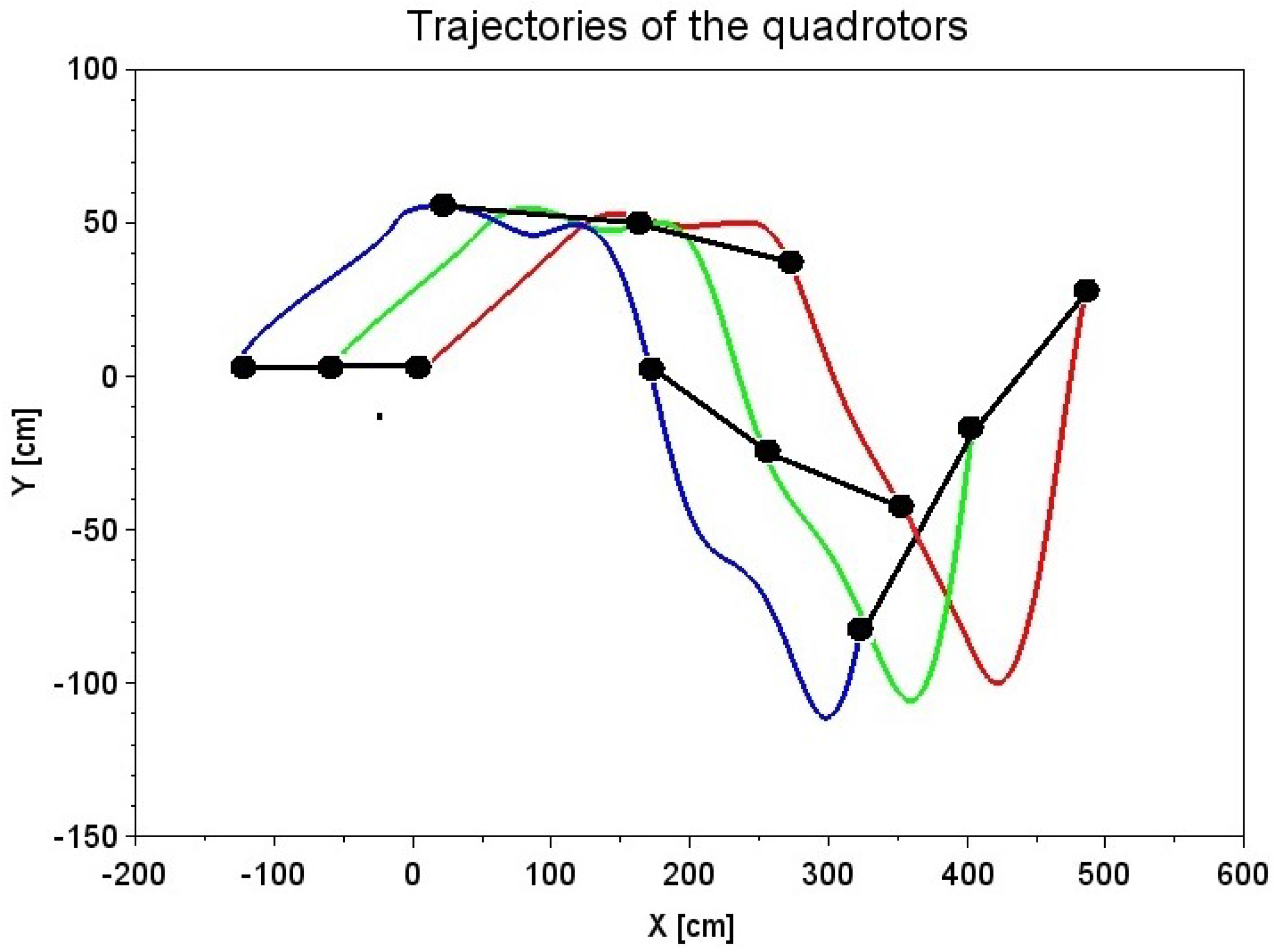
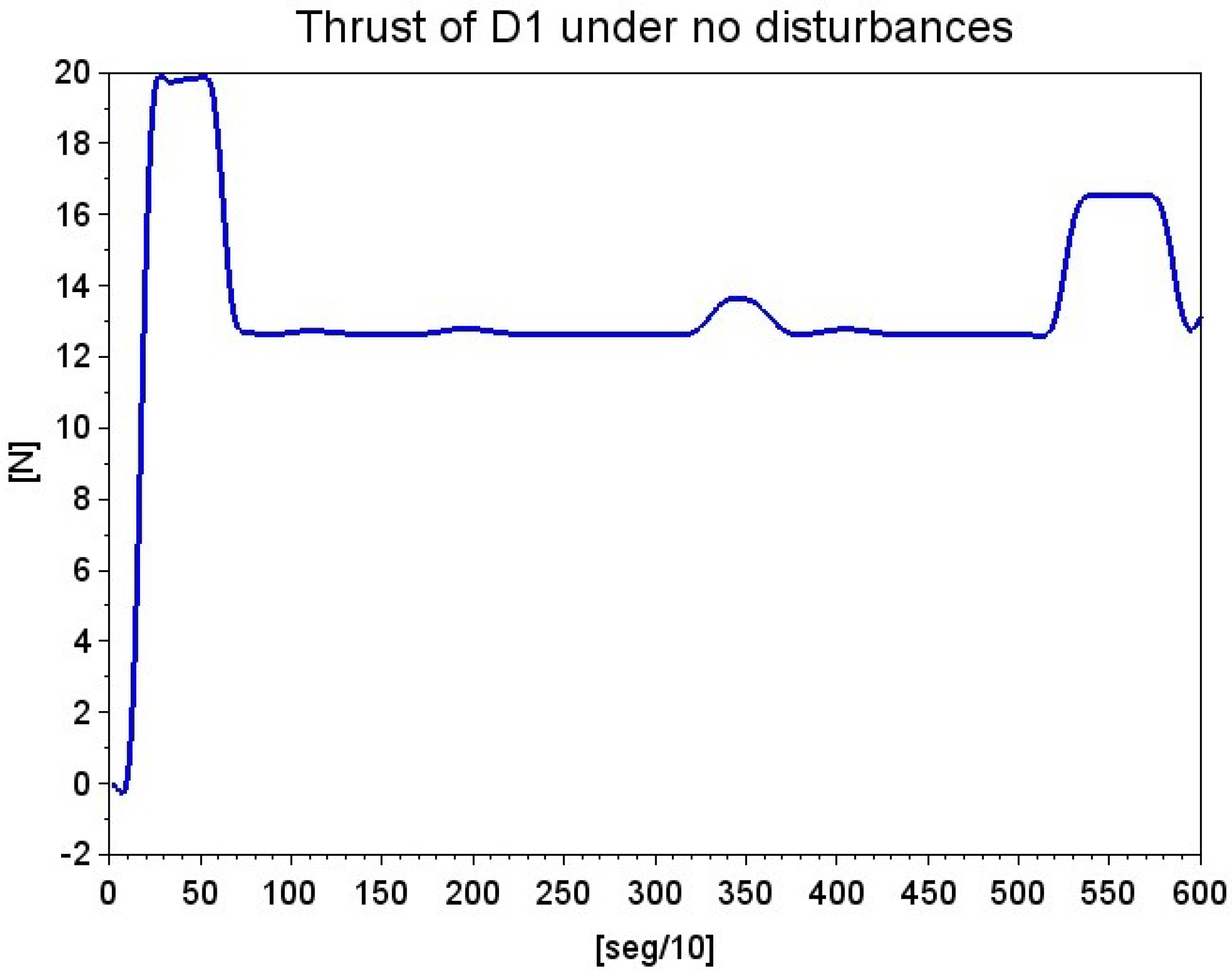
Figure 8 shows the paths followed by the team of quadrotos under wind conditions in a simulation lasting 60 s of simulated time. We found that the drones followed the same path in the repetitions without wind disturbances. Figure 9 shows the position for the three quadrotors and the DLO at different moments of the simulation, where we can observe how the follower drones attempt to keep their linear formation by preserving, as much as possible, the DLO configuration and the distance among quadrotors. In the following, let us denote D 1 , D 2 and D 3 as the leader, mid and rear drones, respectively. Figure 10 and Figure 11 show the plot in time of the thrust of D 1 without and with wind disturbances, respectively. It can be appreciated that the response to the wind perturbations introduces some changes in the thrust profile in order to follow the nominal path as close as possible, thanks to the online tuning of the PD controller by the AFM algorithm.
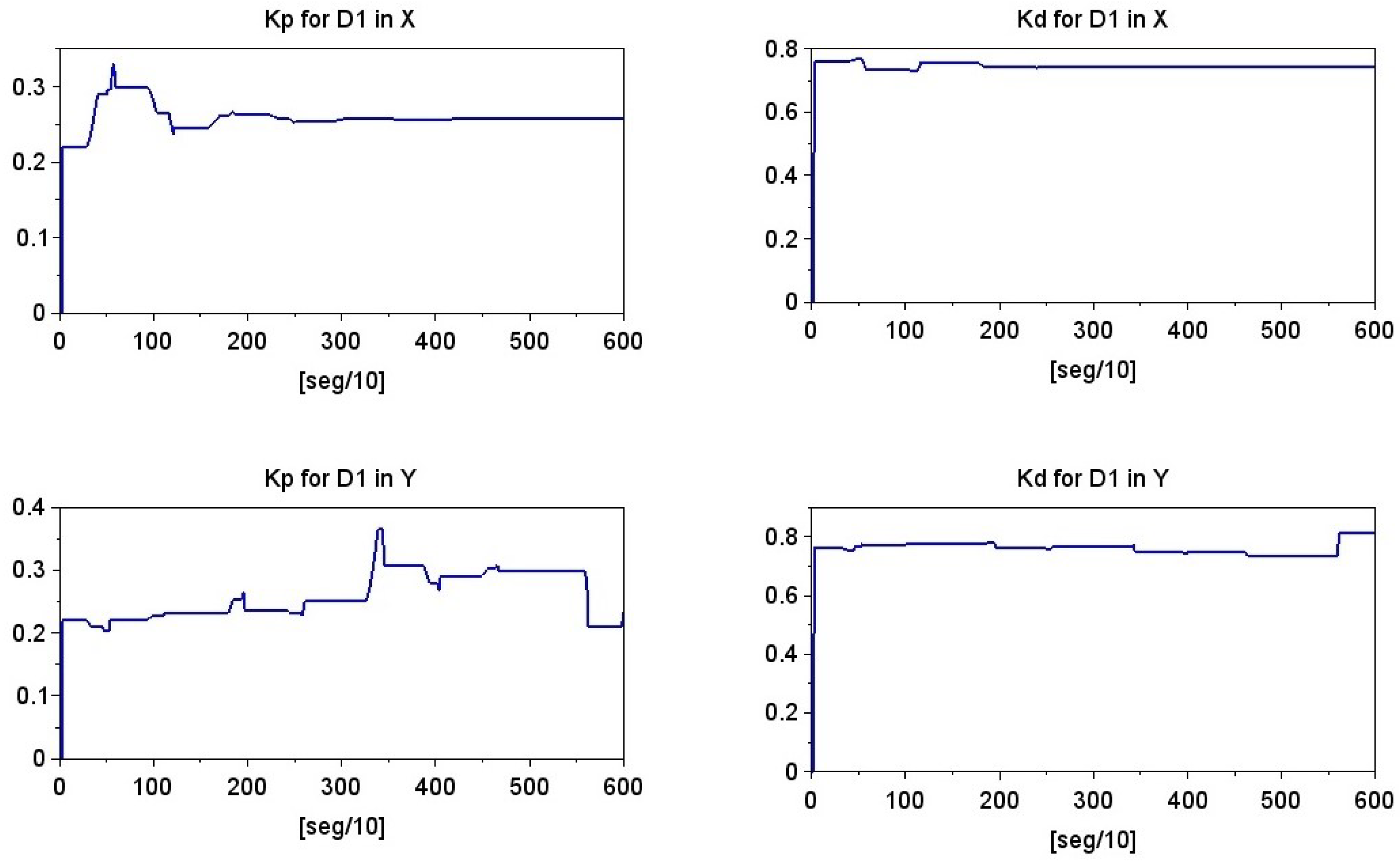
Figure 12 plots the evolution in time of the Euclidean distance between each pair of drones without wind disturbances. Variations around the nominal distance remain bounded. The plots of the temporal evolution of the PD parameters tuned online by the AFM are shown in Figure 13 in both X and Y axes for the simulation under wind disturbances.
At different moments of the simulation, the DLO model switched from a catenary to a parabola model during some short intervals. In particular, in Figure 12, we detect two milestones when switching happens. The first DLO model transition occurs around second 90, when the distance between the robots becomes too big. On the contrary, the second DLO model transition around second 170 occurs because the distance between D 2 and D 3 is too small.
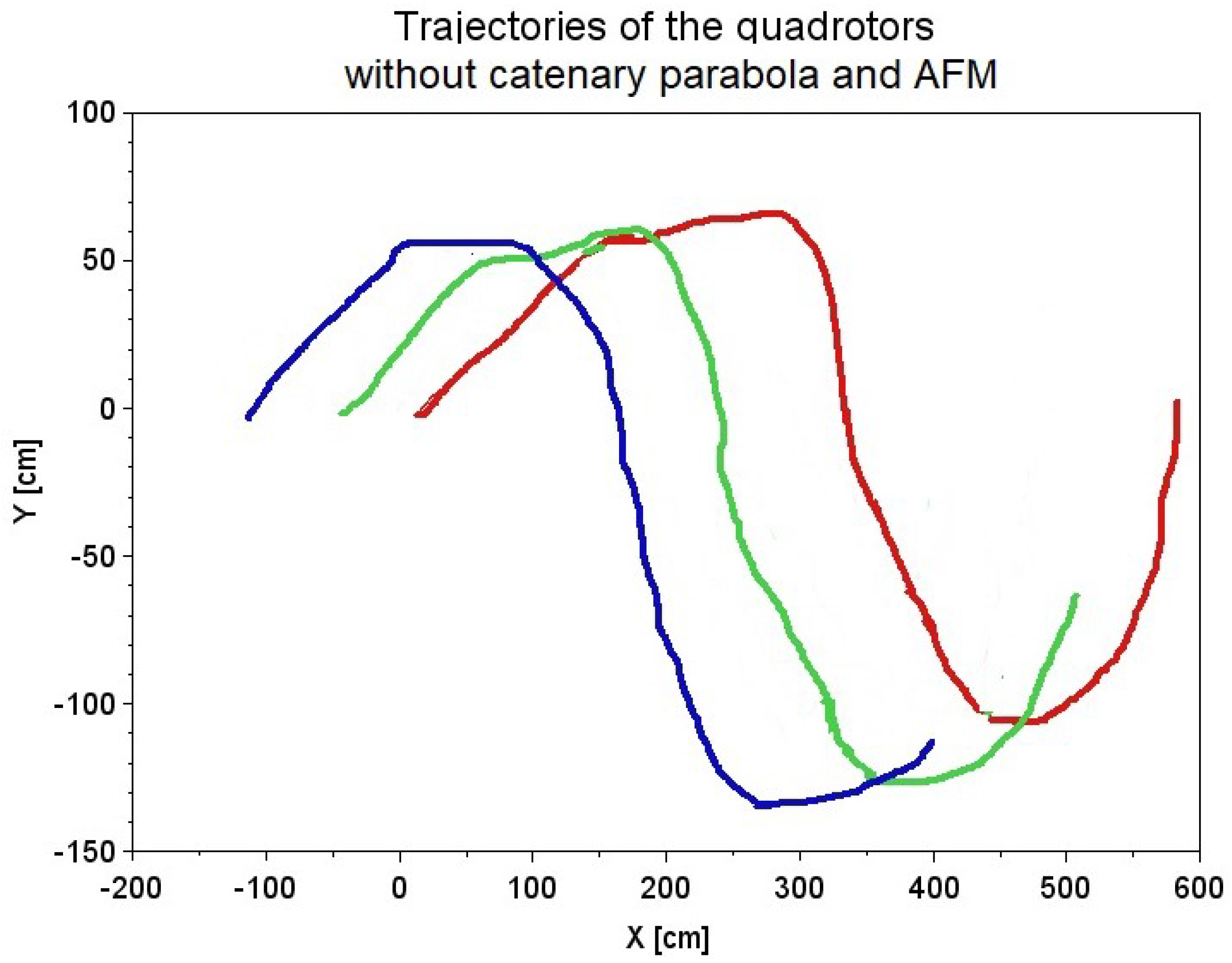
Finally, at the end of the simulation, the cable horizontal distance becomes big again. These instants of transition between DLO models correspond to the first two changes of direction and the final straight trajectory section in Figure 5. However, as we can see, thanks to the proposed hybrid cable modeling, the changes in thrust were bounded in those critical moments, as can be seen in Figure 10 and Figure 11. Finally, Figure 14 shows the trajectories of the three quadrotors when we do not use the DLO model transition from catenary to parabola, nor do we apply the AFM online tuning of the PD controllers. As we can observe, the error of the nominal path following by the drones is large compared to Figure 8, and the drone must follow alternative and wider path curves in order to retain the catenary shape of the DLO. Moreover, the nonadaptive PD control is not able to cope with the sharp corners in the path during transportation.

7.2. Experiment 2

The results from the second experiment are presented in Figure 15 and Figure 16, where the color code of the drone paths remains the same, i.e., the red path corresponds to the leader. As we can observe, the leader drone is subjected to a sudden lateral force when reaching the position at X , Y = 350 , 0 cm that instantaneously displaces it to X , Y = 350 , 80 cm. After that, the leader drone tries to return to the nominal path on the X-axis, recovering from the disturbance. The linkage created by the transported DLO induces a chain reaction over the linear formation of the rest of the drones that alters their motion on the X-axis to follow the leader in the Y direction, although they separate less from the nominal path. Finally, in Figure 16, we can observe the effect of prescinding from the enhanced catenary–parabola DLO model and the AFM effect. As we can observe, the time to recover the nominal path becomes longer, and the approach loses stability.

7.3. Experiment 3

The results from the third experiment are presented in Figure 17 and Figure 18, Color code remains the same as in previous experiments. As we can see on the first image, quadrotors trajectories almost overlap along time; thus, we check that our DLO transport system with drones is able to precisely track the paths in three directions in space. The close performance of the three drones is due to the fact that the spiral path, considering its long enough radius, is not very demanding for the formation of the UAVs due to the lack of sharp angles and sudden direction changes.
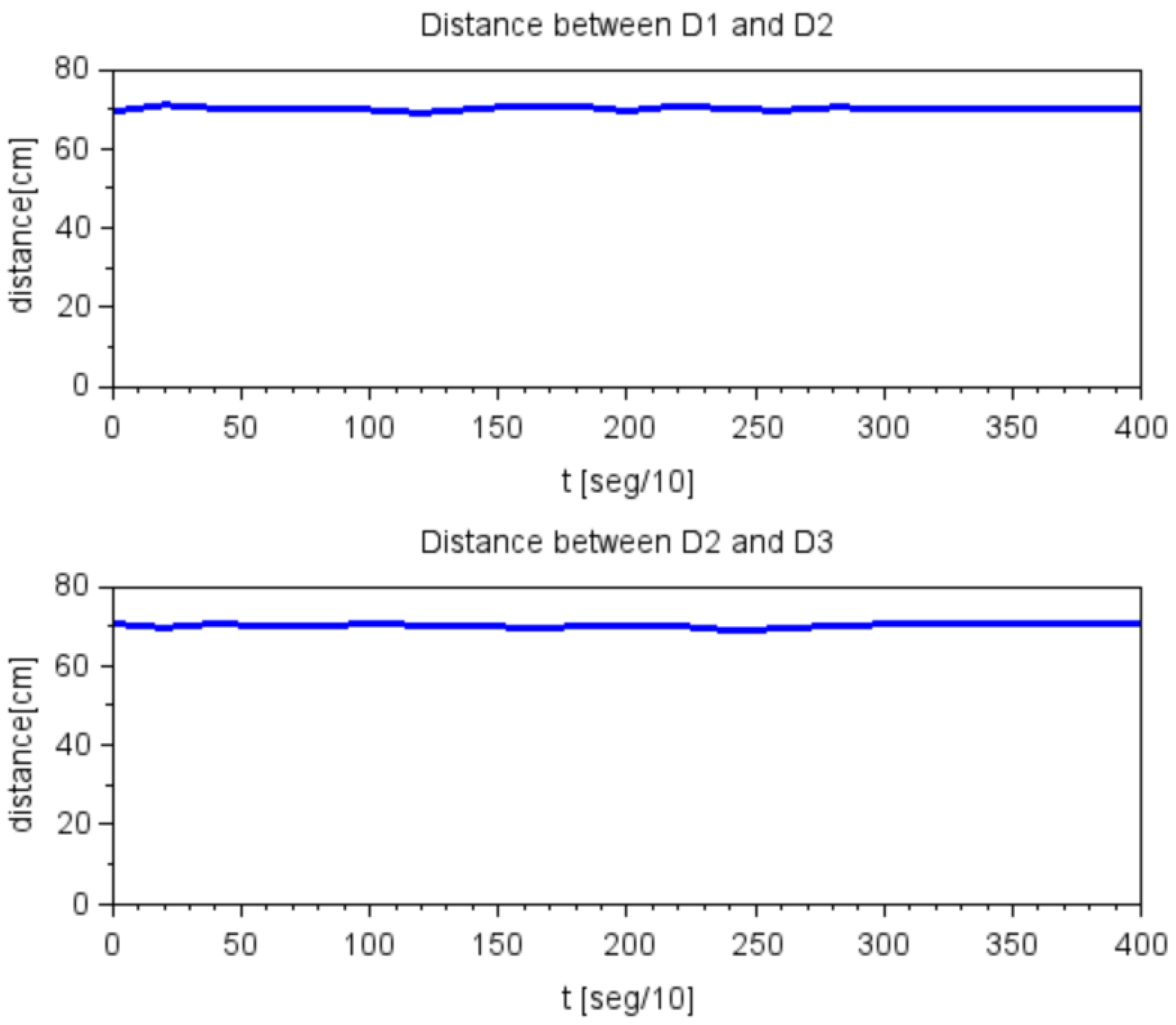
Finally, on Figure 18, we can observe the smooth performance of the three drones reflected on the distance between them along with time. As we can observe, we obtain less irregularities than in Figure 12 of Experiment 1 due to the mentioned fact of ample and constant radius curves.

8. Conclusions

This article shows the robust control of a team of quadrotors for the transportation of a deformable linear object (DLO) following a mission path that featured sharp changes in direction, the influence of sudden strong disturbances and the ability to cope with height-changing spiral paths. The proposed system has a main contribution to the state-of-the-art methods: the hybrid modeling of the DLO sections. Hybrid modeling allows the system to cope with sudden changes in DLO section shapes. Future studies will address the realization of physical experiments to validate the simulation results in a controlled environment by providing the optical tracking of the drones and the shape of the DLO sections. Moreover, research on the design of a type-3 fuzzy logic could permitted the improvement of our control strategy to unknown and dynamic conditions. This type of fuzzy logic has already shown good performance and precision in control problems of renewable energies [70,71]. Another line of future research is the complete modeling of the DLO during the entire flight, including take off and landing when the DLO suffers strong nonlinear effects.

Author Contributions

Conceptualization, J.E. and M.G.; methodology, J.M.L.-G. and M.G.; software, J.E. and G.G.; validation, J.E. and J.M.L.-G.; writing—original draft preparation, J.E.; writing—review and editing, All; funding acquisition, M.G. All authors have read and agreed to the published version of the manuscript.

Funding

This work has been partially supported by spanish MICIN project PID2020-116346GB-I00, and project KK-2021/00070 of the Elkartek 2021 funding program of the Basque Government. This project has received funding from the European Union’s Horizon 2020 research and innovation programme under the Marie Sklodowska-Curie grant agreement No. 777720.

Institutional Review Board Statement

Not applicable.

Informed Consent Statement

Not applicable.

Data Availability Statement

Not applicable.

Conflicts of Interest

The authors declare no conflict of interest.

References

  1. Moshref-Javadi, M.; Hemmati, A.; Winkenbach, M. A truck and drones model for last-mile delivery: A mathematical model and heuristic approach. Appl. Math. Model. 2020, 80, 290–318. [Google Scholar] [CrossRef]
  2. Bonyan Khamseh, H.; Janabi-Sharifi, F.; Abdessameud, A. Aerial manipulation—A literature survey. Robot. Auton. Syst. 2018, 107, 221–235. [Google Scholar] [CrossRef]
  3. Mohammadi, K.; Jafarinasab, M.; Sirouspour, S.; Dyer, E. Decentralized motion control in a cabled-based multi-drone load transport system. In Proceedings of the 2018 IEEE/RSJ International Conference on Intelligent Robots and Systems (IROS), Madrid, Spain, 1–5 October 2018; pp. 4198–4203. [Google Scholar] [CrossRef]
  4. Mohammadi, K.; Sirouspour, S.; Grivani, A. Control of Multiple Quad-Copters With a Cable-Suspended Payload Subject to Disturbances. IEEE/ASME Trans. Mechatron. 2020, 25, 1709–1718. [Google Scholar] [CrossRef]
  5. Al-Kaff, A.; Armingol, J.M.; de La Escalera, A. A vision-based navigation system for Unmanned Aerial Vehicles (UAVs). Integr. Comput. Aided Eng. 2019, 26, 297–310. [Google Scholar] [CrossRef]
  6. Shirani, B.; Najafi, M.; Izadi, I. Cooperative load transportation using multiple UAVs. Aerosp. Sci. Technol. 2019, 84, 158–169. [Google Scholar] [CrossRef]
  7. Thapa, S.; Bai, H.; Acosta, J. Cooperative aerial load transport with force control. IFAC-PapersOnLine 2018, 51, 38–43. [Google Scholar] [CrossRef]
  8. Michael, N.; Shen, S.; Mohta, K.; Kumar, V.; Nagatani, K.; Okada, Y.; Kiribayashi, S.; Otake, K.; Yoshida, K.; Ohno, K.; et al. Collaborative mapping of an earthquake damaged building via ground and aerial robots. In Springer Tracts in Advanced Robotics; Springer: Cham, Switzerland, 2014; pp. 33–47. [Google Scholar]
  9. Ando, H.; Ambe, Y.; Ishii, A.; Konyo, M.; Tadakuma, K.; Maruyama, S.; Tadokoro, S. Aerial hose type robot by water jet for fire fighting. IEEE Robot. Autom. Lett. 2018, 3, 1128–1135. [Google Scholar] [CrossRef]
  10. Aminifar, F.; Rahmatian, F. Unmanned Aerial Vehicles in Modern Power Systems: Technologies, Use Cases, Outlooks, and Challenges. IEEE Electrif. Mag. 2020, 8, 107–116. [Google Scholar] [CrossRef]
  11. Suzuki, M.; Yokota, S.; Matsumoto, A.; Chugo, D.; Hashimoto, H. Liquid feeding system using cooperative towing by multiple drones—2nd Report: Position estimation of each drones based on catenary theory and tensile force of tube. In Proceedings of the 2018 IEEE International Conference on Industrial Technology (ICIT), Lyon, France, 19–22 February 2018; pp. 217–222. [Google Scholar] [CrossRef]
  12. Suzuki, M.; Yokota, S.; Imadu, A.; Matsumoto, A.; Chugo, D.; Hashimoto, H. Liquid feeding system using cooperative towing by multiple drones—1st report: Derivation of the flyable range while towing a tube. In Proceedings of the 2017 26th IEEE International Symposium on Robot and Human Interactive Communication (RO-MAN), Lisbon, Portugal, 28–31 August 2017; pp. 1228–1233. [Google Scholar] [CrossRef]
  13. D’Antonio, D.S.; Cardona, G.A.; Saldaña, D. The Catenary Robot: Design and Control of a Cable Propelled by Two Quadrotors. IEEE Robot. Autom. Lett. 2021, 6, 3857–3863. [Google Scholar] [CrossRef]
  14. Sreenath, K.; Kumar, V. Dynamics, control and planning for cooperative manipulation of payloads suspended by cables from multiple quadrotor robots. In Proceedings of the Robotics: Science and Systems (RSS), Berlin, Germany, 24–28 June 2013. [Google Scholar]
  15. Kotaru, P.; Sreenath, K. Multiple quadrotors carrying a flexible hose: Dynamics, differential flatness and control. IFAC-PapersOnLine 2020, 53, 8832–8839. [Google Scholar] [CrossRef]
  16. Aström, K.J.; Hägglund, T. PID Controllers: Theory, Design, and Tuning, 2nd ed.; Instrument Society of America: Research Triangle Park, NC, USA, 1995. [Google Scholar]
  17. Estevez, J.; Lopez-Guede, J.M.; Graña, M. Particle Swarm Optimization Quadrotor Control for Cooperative Aerial Transportation of Deformable Linear Objects. Cybern. Syst. 2016, 47, 4–16. [Google Scholar] [CrossRef]
  18. Estevez, J.; Graña, M.; Lopez-Guede, J.M. Online fuzzy modulated adaptive PD control for cooperative aerial transportation of deformable linear objects. Integr. Comput. Aided Eng. 2017, 24, 41–55. [Google Scholar] [CrossRef]
  19. Wei, K.; Zhang, L.X.; Ren, A.D. The analysis method of highline cable of alongside replenishment system based on suspended cable theory. In Advanced Materials Research; Trans Tech Publications: Zurich, Switzerland, 2012; Volume 490, pp. 633–637. [Google Scholar]
  20. Su, Y.; Qiu, Y.; Liu, P. Optimal cable tension distribution of the high-speed redundant driven camera robots considering cable sag and inertia effects. Adv. Mech. Eng. 2014, 6, 729020. [Google Scholar] [CrossRef] [Green Version]
  21. Hsu, Y.; Pan, C. The static WKB solution to catenary problems with large sag and bending stiffness. Math. Probl. Eng. 2014, 11, 231726. [Google Scholar] [CrossRef] [Green Version]
  22. Choo, Y.I.; Casarella, M.J. A Survey of Analytical Methods for Dynamic Simulation of Cable-Body Systems. J. Hydronaut. 1973, 7, 137–144. [Google Scholar] [CrossRef]
  23. Van Nieuwstadt, M.J.; Murray, R.M. Real-time trajectory generation for differentially flat systems. Int. J. Robust Nonlinear Control 1998, 8, 995–1020. [Google Scholar] [CrossRef]
  24. Andreu, A.; Gil, L.; Roca, P. A new deformable catenary element for the analysis of cable net structures. Comput. Struct. 2006, 84, 1882–1890. [Google Scholar] [CrossRef]
  25. Li, C.; He, J.; Zhang, Z.; Liu, Y.; Ke, H.; Dong, C.; Li, H. An improved analytical algorithm on main cable system of suspension bridge. Appl. Sci. 2018, 8, 1358. [Google Scholar] [CrossRef] [Green Version]
  26. Pan, Q.; Yan, D.; Yi, Z. Form-Finding Analysis of the Rail Cable Shifting System of Long-Span Suspension Bridges. Appl. Sci. 2018, 8, 2033. [Google Scholar] [CrossRef] [Green Version]
  27. Skop, R.A.; Choo, Y.I. The configuration of a cable towed in a circular path. J. Aircr. 1971, 8, 856–862. [Google Scholar] [CrossRef]
  28. Irvine, H.M. Cable Structures; MIT Press: Cambridge, MA, USA, 1981. [Google Scholar]
  29. Clifton, J.M.; Schmidt, L.V.; Stuart, T.D. Dynamic modeling of a trailing wire towed by an orbiting aircraft. J. Guid. Control Dyn. 1995, 18, 875–881. [Google Scholar] [CrossRef]
  30. Dreyer, T.; Vuuren, J.H.V. A comparison between continuous and discrete modelling of cables with bending stiffness. Appl. Math. Model. 1999, 23, 527–541. [Google Scholar] [CrossRef]
  31. Yamaguchi, S.; Koterayama, W.; Yokobiki, T. Development of a motion control method for a towed vehicle with a long cable. In Proceedings of the 2000 International Symposium on Underwater Technology (Cat. No. 00EX418), Tokyo, Japan, 26 May 2000; pp. 491–496. [Google Scholar]
  32. Gobat, J.I.; Grosenbaugh, M.A. Dynamics in the touchdown region of catenary moorings. Int. J. Offshore Polar Eng. 2001, 11, 4. [Google Scholar]
  33. Turkyilmaz, Y.; Egeland, O. Active depth control of towed cables in 2D. In Proceedings of the 40th IEEE Conference on Decision and Control (Cat. No. 01CH37228), Orlando, FL, USA, 4–7 December 2001; Volume 1, pp. 952–957. [Google Scholar]
  34. McKerrow, P.J.; Ratner, D. The design of a tethered aerial robot. In Proceedings of the 2007 IEEE International Conference on Robotics and Automation 2007, Rome, Italy, 10–14 April 2007; pp. 355–360. [Google Scholar]
  35. Ren, W.X.; Huang, M.G.; Hu, W.H. A parabolic cable element for static analysis of cable structures. Eng. Comput. 2008, 25, 366–384. [Google Scholar] [CrossRef]
  36. Chatjigeorgiou, I.K. A finite differences formulation for the linear and nonlinear dynamics of 2D catenary risers. Ocean. Eng. 2008, 35, 616–636. [Google Scholar] [CrossRef]
  37. Maza, I.; Kondak, K.; Bernard, M.; Ollero, A. Multi-UAV Cooperation and Control for Load Transportation and Deployment. J. Intell. Robot. Syst. 2009, 57, 417–449. [Google Scholar] [CrossRef]
  38. Michael, N.; Fink, J.; Kumar, V. Cooperative manipulation and transportation with aerial robots. Auton. Robot. 2010, 30, 73–86. [Google Scholar] [CrossRef] [Green Version]
  39. Gouttefarde, M.; Collard, J.F.; Riehl, N.; Baradat, C. Simplified static analysis of large-dimension parallel cable-driven robots. In Proceedings of the 2012 IEEE International Conference on Robotics and Automation, Saint Paul, MN, USA, 14–18 May 2012; pp. 2299–2305. [Google Scholar]
  40. Jiang, Q.; Kumar, V. Determination and Stability Analysis of Equilibrium Configurations of Objects Suspended From Multiple Aerial Robots. J. Mech. Robot. 2012, 4, 021005. [Google Scholar] [CrossRef]
  41. Lupashin, S.; D’Andrea, R. Stabilization of a flying vehicle on a taut tether using inertial sensing. In Proceedings of the 2013 IEEE/RSJ International Conference on Intelligent Robots and Systems, Tokyo, Japan, 3–7 November 2013; pp. 2432–2438. [Google Scholar] [CrossRef]
  42. Nguyen, D.Q.; Gouttefarde, M.; Company, O.; Pierrot, F. On the simplifications of cable model in static analysis of large-dimension cable-driven parallel robots. In Proceedings of the 2013 IEEE/RSJ International Conference on Intelligent Robots and Systems, Tokyo, Japan, 3–7 November 2013; pp. 928–934. [Google Scholar]
  43. Lee, T. Geometric controls for a tethered quadrotor UAV. In Proceedings of the 54th IEEE Conference on Decision and Control (CDC), Osaka, Japan, 15–18 December 2015; pp. 2749–2754. [Google Scholar] [CrossRef] [Green Version]
  44. Goodarzi, F.A.; Lee, T. Dynamics and control of quadrotor UAVs transporting a rigid body connected via flexible cables. In Proceedings of the American Control Conference (ACC), Chicago, IL, USA, 1–3 July 2015; pp. 4677–4682. [Google Scholar]
  45. Estevez, J.; Lopez-Guede, J.M.; Graña, M. Quasi-stationary state transportation of a hose with quadrotors. Robot. Auton. Syst. 2015, 63 Pt 2, 187–194. [Google Scholar] [CrossRef]
  46. Doroudgar, S. Static and Dynamic Modeling and Simulation of the Umbilical Cable in A Tethered Unmanned Aerial System. Ph.D. Thesis, Simon Fraser University, Burnaby, BC, Canada, 2016. [Google Scholar]
  47. Laranjeira, M.; Dune, C.; Hugel, V. Catenary-based visual servoing for tethered robots. In Proceedings of the 2017 IEEE International Conference on Robotics and Automation (ICRA), Singapore, 29 May–3 June 2017; pp. 732–738. [Google Scholar]
  48. Abiko, S.; Kuno, A.; Narasaki, S.; Oosedo, A.; Kokubun, S.; Uchiyama, M. Obstacle avoidance flight and shape estimation using catenary curve for manipulation of a cable hanged by aerial robots. In Proceedings of the 2017 IEEE International Conference on Robotics and Biomimetics (ROBIO), Macau, 5–8 December 2017; pp. 2099–2104. [Google Scholar]
  49. Mansour, A.; Mekki, O.B.; Montassar, S.; Rega, G. Catenary-induced geometric nonlinearity effects on cable linear vibrations. J. Sound Vib. 2018, 413, 332–353. [Google Scholar] [CrossRef]
  50. Ahmadi-Kashani, K. Development of Cable Elements and Their Applications in the Analysis of Cable Structures. Ph.D. Thesis, University of Manchester Institute of Science and Technology (UMIST), Oxford, MA, USA, 1983. [Google Scholar]
  51. Tibert, G. Numerical Analyses of Cable Roof Structures. Ph.D. Thesis, KTH, Stockholm, Sweden, 1999. [Google Scholar]
  52. White, N.N. Evolution of the Design and Modeling of the Eagle System. Ph.D. Thesis, Case Western Reserve University, Cleveland, OH, USA, 2011. [Google Scholar]
  53. Chaterjee, N.; Nita, B.G. The hanging cable problem for practical applications. Atl. Electron. J. Math. 2010, 4, 70–77. [Google Scholar]
  54. Perkins, N.; Mote, C., Jr. Three-dimensional vibration of travelling elastic cables. J. Sound Vib. 1987, 114, 325–340. [Google Scholar] [CrossRef]
  55. Yao, R.; Tang, X.; Wang, J.; Huang, P. Dimensional optimization design of the four-cable-driven parallel manipulator in fast. IEEE/ASME Trans. Mechatron. 2009, 15, 932–941. [Google Scholar] [CrossRef]
  56. Larsen, L.; Pham, V.L.; Kim, J.; Kupke, M. Collision-free path planning of industrial cooperating robots for aircraft fuselage production. In Proceedings of the 2015 IEEE International Conference on Robotics and Automation (ICRA), Seattle, WA, USA, 26–30 May 2015; pp. 2042–2047. [Google Scholar]
  57. Hatibovic, A.; Kádár, P. The application of autonomous drones in the environment of overhead lines. In Proceedings of the 2018 IEEE 18th International Symposium on Computational Intelligence and Informatics (CINTI), Budapest, Hungary, 21–22 November 2018; pp. 289–294. [Google Scholar]
  58. Oh, J.; Lee, C. 3D power line extraction from multiple aerial images. Sensors 2017, 17, 2244. [Google Scholar] [CrossRef] [PubMed] [Green Version]
  59. Tang, X. An overview of the development for cable-driven parallel manipulator. Adv. Mech. Eng. 2014, 6, 823028. [Google Scholar] [CrossRef] [Green Version]
  60. Qiu, H.; Duan, H. Pigeon interaction mode switch-based UAV distributed flocking control under obstacle environments. ISA Trans. 2017, 71, 93–102. [Google Scholar] [CrossRef]
  61. Cruz, P.J.; Fierro, R. Cable-suspended load lifting by a quadrotor UAV: Hybrid model, trajectory generation, and control. Auton. Robot. 2017, 41, 1629–1643. [Google Scholar] [CrossRef]
  62. Kang, Y.; Hedrick, J.K. Linear tracking for a fixed-wing UAV using nonlinear model predictive control. IEEE Trans. Control Syst. Technol. 2009, 17, 1202–1210. [Google Scholar] [CrossRef]
  63. Pruner, E.; Necsulescu, D.; Sasiadek, J.; Kim, B. Control of decentralized geometric formations of mobile robots. In Proceedings of the 2012 17th International Conference on Methods & Models in Automation & Robotics (MMAR), Miedzyzdroje, Poland, 27–30 August 2012; pp. 627–632. [Google Scholar]
  64. Brandão, A.S.; Sarcinelli-Filho, M. On the guidance of multiple uav using a centralized formation control scheme and delaunay triangulation. J. Intell. Robot. Syst. 2016, 84, 397–413. [Google Scholar] [CrossRef]
  65. Lee, T.; Sreenath, K.; Kumar, V. Geometric control of cooperating multiple quadrotor UAVs with a suspended payload. In Proceedings of the 52nd IEEE Conference on Decision and Control, Firenze, Italy, 10–13 December 2013; pp. 5510–5515. [Google Scholar]
  66. Mercado, D.A.; Castro, R.; Lozano, R. Quadrotors flight formation control using a leader-follower approach. In Proceedings of the 2013 European Control Conference (ECC), Zürich, Switzerland, 17–19 July 2013. [Google Scholar]
  67. Wen, N.; Zhao, L.; Su, X.; Ma, P. UAV online path planning algorithm in a low altitude dangerous environment. IEEE/CAA J. Autom. Sin. 2015, 2, 173–185. [Google Scholar] [CrossRef]
  68. Yeh, F.K. Attitude controller design of mini-unmanned aerial vehicles using fuzzy sliding-mode control degraded by white noise interference. Control. Theory Appl. IET 2012, 6, 1205–1212. [Google Scholar] [CrossRef]
  69. Takagi, T.; Sugeno, M. Fuzzy identification of systems and its applications to modeling and control. IEEE Trans. Syst. Man Cybern. 1985, 15, 116–132. [Google Scholar] [CrossRef]
  70. Liu, Z.; Mohammadzadeh, A.; Turabieh, H.; Mafarja, M.; Band, S.S.; Mosavi, A. A new online learned interval type-3 fuzzy control system for solar energy management systems. IEEE Access 2021, 9, 10498–10508. [Google Scholar] [CrossRef]
  71. Mosavi, A.; Qasem, S.N.; Shokri, M.; Band, S.S.; Mohammadzadeh, A. Fractional-order fuzzy control approach for photovoltaic/battery systems under unknown dynamics, variable irradiation and temperature. Electronics 2020, 9, 1455. [Google Scholar] [CrossRef]
Figure 1. Overall block diagram.
Applsci 12 05253 g001
Figure 2. Visual comparison of the catenary and parabola curves with parameter a.
Applsci 12 05253 g002
Figure 3. Follow-the-leader platoon model.
Applsci 12 05253 g003
Figure 4. Control system for each UAV in the system.
Applsci 12 05253 g004
Figure 5. Nominal path for the drone leader in Experiment 1, featuring sharp changes in direction.
Applsci 12 05253 g005
Figure 6. Experiment 2. Nominal path followed by the leader drone suffering a sudden lateral disturbance.
Applsci 12 05253 g006
Figure 7. Spiral 3D ascending path in Experiment 3.
Applsci 12 05253 g007
Figure 8. Trajectory of the quadrotors in Experiment 1 under wind perturbations. Color code: red, green and blue correspond to leader, mid and rear drones, respectively.
Applsci 12 05253 g008
Figure 9. Position of the drones and the DLO at different moments of Experiment 1. Color code: red, green and blue correspond to leader, mid and rear drones, respectively.
Applsci 12 05253 g009
Figure 10. Plot of the instantaneous thrust of leader drone ( D 1 ) during the simulation without wind disturbances.
Applsci 12 05253 g010
Figure 11. Plot of the instantaneous thrust of leader drone ( D 1 ) during the simulation under wind disturbances.
Applsci 12 05253 g011
Figure 12. Euclidean distance along time between each pair of drones transporting the DLO in Experiment 1 without wind perturbations.
Applsci 12 05253 g012
Figure 13. Instantaneous values of the AFM online-tuned parameters of the PD controller of D 1 along both X and Y axes.
Applsci 12 05253 g013
Figure 14. Trajectoriesof the quadrotors in Experiment 1 when neither the catenary-parabola approximation nor the online AFM tuning of the PD controllers were applied. Color code: red, green and blue correspond to leader, mid and rear drones, respectively.
Applsci 12 05253 g014
Figure 15. Trajectories of the quadrotors in Experiment 2. Color code: red, green and blue correspond to leader, mid and rear drones.
Applsci 12 05253 g015
Figure 16. Trajectories of the quadrotors in Experiment 2 when neither catenary–parabola approximation nor the online AFM tuning of the PD controllers are applied. Color code: red, green and blue correspond to leader, mid and rear drones.
Applsci 12 05253 g016
Figure 17. Trajectories of the three quadrotors in Experiment 3. Color code: red, green and blue correspond to leader, mid and rear drones.
Applsci 12 05253 g017
Figure 18. Euclidean distance along time between drones in Experiment 3.
Applsci 12 05253 g018
Table 2. Quadrotor structural and dynamic parameters.
ParameterValue
mass, m0.5 kg
arm length, l25 cm
inertia moments, I x x = I y y 5 × 10 3 [ Nms 2 ]
inertia moment, I z z 1 × 10 2 [ Nms 2 ]
propeller thrust coefficient, b 3 × 10 6 [ Ns 2 ]
drag, d 1 × 10 7 [ Nms 2 ]
Publisher’s Note: MDPI stays neutral with regard to jurisdictional claims in published maps and institutional affiliations.