Next Article in Journal
The Characterization of Shale Differences Based on Petrophysical Properties and Pore Structure: A Case Study of the Longmaxi Formation in Northern Guizhou Province and the Yanchang Formation in the Ordos Basin
Previous Article in Journal
Digital Function Modeling in Graph-Based Design Languages
 
 
applsci-logo
Article Menu

Article Menu

Article

Performance Analysis of Acceleration and Inertial Force of Electromagnetic Suspension Inertial Stabilizer

1
College of Mechanical & Electrical Engineering, Nanjing University of Aeronautics and Astronautics, Nanjing 210016, China
2
College of Mechanical and Electrical Engineering, Jinling Institute of Technology, Nanjing 211169, China
*
Author to whom correspondence should be addressed.
Appl. Sci. 2022, 12(11), 5304; https://doi.org/10.3390/app12115304
Submission received: 28 March 2022 / Revised: 15 May 2022 / Accepted: 22 May 2022 / Published: 24 May 2022
(This article belongs to the Topic Advanced Systems Engineering: Theory and Applications)

Abstract

:
In this paper, the structural characteristics of electromagnetic suspension (EMS) inertial stabilizers are analyzed firstly, and then a mechanical analysis of a single mass block and double mass block is carried out. The relationship model between the inertial anti-rolling mass block and inertial force transmitted to the ship is established. The inertial force is determined by the number of coil turns, coil current, mass block, mass of the ship, electromagnet current, rate of change of the electromagnet current, air gap between the electromagnet and inertial mass block, and rotational angular speed. Through theoretical analysis, it is found that the response speed of inertia force is directly related to the electromagnetic coil current, the voltage at both ends of the electromagnetic coil, the coil resistance and the air gap. It is concluded that the response speed of the inertia force can be controlled by controlling the coil current, adjusting the voltage at both ends of the coil and adjusting the air gap. The inductance of the electromagnetic coil will also increase the nonlinearity of the inertial anti-roll system. On the basis of theoretical analysis, a digital simulation of EMS inertial stabilizer is carried out by MATLAB and ANSYS MAXWELL2D. Finally, a single mass block system of EMS inertial stabilizer is designed and tested. During the test, a 1.5 V sinusoidal excitation voltage is added to the electromagnetic coil after the mass block is suspended stably, and the maximum acceleration values of the inertial anti-rolling mass block and hull are 10.29 m/s2 and 1.27 m/s2. Finally, the theoretical analysis results, digital simulation results and experimental results are analyzed, which verifies the correctness of the acceleration and inertia force performance analysis of the EMS inertial stabilizer.

1. Introduction

EMS has the advantage of noncontact force transmission, and active EMS devices also have the advantages of a small occupied space and good controllability. It has been widely used in magnetic bearings [1,2,3,4], EMS motors [5,6], EMS trains [7,8], mechanical vibration suppression and isolation [9,10], EMS tracks [11,12], etc., but it is rarely used in the field of ship anti-rolling. At present, there is basically no single traditional anti-roll device except the fin that can have good anti-rolling effect under all working conditions (various ship speeds, various wave directions, etc.). Therefore, it is urgent to carry out research on new anti-roll devices that can have a good stabilizing effect under all working conditions. Some scholars have designed a small ship model, suspended the anti-rolling weight by applying EMS technology, controlled the anti-rolling weight by ship swing parameters, and changed the center of gravity of the ship model structure. The anti-rolling effect of the model structure was verified by simulation [13]. Some scholars have designed vertical anti-rolling weights on the boat model and realized anti-rolling by applying the Coriolis effect [14]. Some other scholars have designed a Marine permanent magnet maglev anti-rocking automatic balance system [15]. The mass block is driven to the high side of the ship’s rocking through the linear motor, so the purpose of reducing the rolling of the ship is achieved. Other scholars have studied the ship torque gyro anti-roll device [16]. The gyro rotor is controlled by a magnetic powder brake to realize the control of gyroscopic torque, and the goal of ship roll suppression is ultimately achieved. In the early stages of this study, research on the supporting characteristics of the permanent EMS active mass block [17] and on the anti-rolling mechanism of the EMS inertial anti-rolling mass block [18] was carried out by the authors. The anti-rolling effect of the EMS inertial stabilizer mainly depends on the accuracy of the acceleration control of the inertial anti-rolling mass block. In order to ensure the accurate control of the inertial mass block, it is necessary to study its acceleration and inertial force characteristics. The performance of the acceleration and inertial force of the maglev inertial anti-rolling mass block is studied.

2. Modeling and Mechanical Analysis of EMS Inertial Anti-Rolling Mass Block

2.1. Structural Diagram of EMS Inertia Stabilizer

Figure 1 shows the cross-sectional diagram of the ship. The EMS inertial stabilizer studied is mainly composed of an inertial anti-rolling mass block, electromagnet, controller, power amplifier, acceleration sensor and displacement sensor. The inertia anti-rolling mass block consists of left and right mass blocks. There are four independently controlled electromagnets, which are the upper left electromagnet, lower left electromagnet, upper right electromagnet and lower right electromagnet. Because the left and right structures of the ship itself are symmetrical, in order to not destroy the symmetry of the ship structure and achieve a good anti-rolling effect, the structure of the electromagnet of the upper left mass should be the same as that of the upper right mass as much as possible, and the and structure of the electromagnet of the lower left mass should be the same as that of the lower right mass as muchas possible. In the absence of external interference such as sea waves, the ship should ensurethat the mass blockis stably suspended between the upper and lower electromagnets. In order to overcome the gravity of the mass block, the upper electromagnets need to provide electromagnetic force.

2.2. Mechanical Analysis of Single Mass Block of EMS Inertia Stabilizer

The inertial anti-rolling mass block is suspended between the upper and lower electromagnets without an external disturbance force. The air gap between the mass block and the upper and lower electromagnets is basically the same and is set to g 0 . Assuming that the ship is subjected to external interference forces such as sea waves with counterclockwise F s i n ω t , the ship would roll counterclockwise, as shown in Figure 2, while the mass block would remain unchanged due to inertia. Because of the symmetry of the structure, the forces on the left and right inertial anti-rolling mass blocks are also symmetrical, so we only analyzed the forces on the right mass block. The gap between the right mass block and the upper right electromagnet becomes larger. Assuming that the gap becomes g 0 + x , the gap between the right mass block and the lower right electromagnet becomes smaller. Assuming that the gap becomes g 0 x , the right mass blockwould be subjected to three forces, namely gravity F G , electromagnetic force F M and Coriolis force F C . Assuming that the static equilibrium position of the inertial anti-rolling mass block as the coordinate origin, the dynamic model of the right inertial anti-rolling mass block and the ship can be described as follows:
{ m x ¨ 1 ( t ) = F MR + F C F G + ( k 1 + k 2 ) [ x 2 ( t ) x 1 ( t ) ] M x ¨ 2 ( t ) = F s i n ω t F MR F C ( k 1 + k 2 ) [ x 2 ( t ) x 1 ( t ) ]
In Equation(1), k 1   and   k 2 are the support stiffness coefficients between the mass block and the upper right and lower right electromagnet, k 1 = N 2 A μ 0 i 0 U g 0 2 d i d x + N 2 A μ 0 i 0 U 2 g 0 3 [19]; k 2 = N 2 A μ 0 i 0 D g 0 2 d i d x + N 2 A μ 0 i 0 D 2 g 0 3 [19]. Gravity: F G = m g ; electromagnetic force: F M = N 2 i 2 A μ 0 4 g 0 2 ; Coriolis force: F C = 2 m ω × v . N is the number of turns of the electromagnet coil, A is the cross-sectional area of the electromagnet core, μ 0 is the relative permeability of air, i 0 U and i 0 D are the coil currents of upper right electromagnet and lower right electromagnet, respectively, m is the mass of the right mass block, g is the acceleration of gravity, ω is the angular speed of the ship rotating counterclockwise, and v is the speed of the mass block along the Z coordinate direction d x / d t .
The Coriolis force exists because of the relative motion of particles and the rotation of the reference frame, and its direction is perpendicular to the direction of angular speed and relative motion speed. Along the horizontal direction of the ship, that is, the Y coordinate direction in Figure 2, because the angular speed of the ship is constantly changing with external disturbances such as sea waves, the direction of the Coriolis force F C is also constantly changing. In this direction, the force on the mass block is:
F Y = F C F G s i n ω t = 2 m ω × v m g s i n ω t
According to Equation (2), the force of the right mass block in the Y coordinate direction mainly depends on the angular speed of ship rotation and the mass of the mass block. In order to prevent the mass block from moving along the Y direction due to the force in the Y direction, a positioning axis is set in the middle of the mass block, which passes through the geometric center of the upper right and lower right electromagnets and is fixed with the mass block as a whole. Because the speed d x / d t of the mass block is small, the Coriolis force F C is also small, and the force on the mass block in the Y direction can be cancelled by the positioning axis, that is, F Y 0 .
As shown in Figure 2, the force on the right mass block in the Z coordinate direction is:
                        F Z = F M R F G c o s ω t
where F M R is the resultant force of upper and lower electromagnetic forces on the right side, as in Equation (4).
F M R = F M U F M D = N 2 A μ 0 i 0 U 2 4 ( g 0 + x ) 2 N 2 A μ 0 i 0 D 2 4 ( g 0 x ) 2
From above, we can obtain:
F Z = N 2 A μ 0 i 0 U 2 4 ( g 0 + x ) 2 N 2 A μ 0 i 0 D 2 4 ( g 0 x ) 2 m g c o s ω t
Set { x 1 ( t ) = X 10 s i n ω t x 2 ( t ) = X 20 s i n ω t , and place it in the line after Equation (1):
{ x 1 ( t ) = F Z ( k 1 k 2 M ω 2 ) + ( k 1 k 2 ) ( F s i n ω t F M R ) [ m M ω 2 ( k 1 k 2 ) ( m + M ) ] ω 2 x 2 ( t ) = F Z ( k 1 k 2 ) + ( k 1 k 2 m ω 2 ) ( F s i n ω t F M R ) [ m M ω 2 ( k 1 k 2 ) ( m + M ) ] ω 2
{ x ¨ 1 ( t ) = ( k 1 k 2 ) F s i n ω t ( k 1 k 2 ) ( m + M ) m M ω 2 x ¨ 2 ( t ) = ( k 1 k 2 m ω 2 ) F s i n ω t ( k 1 k 2 ) ( m + M ) m M ω 2
In order to obtain a large inertial force on the ship base, i.e., M x ¨ 2 ( t ) , the support stiffness coefficient k 2 between the mass block and the lower right electromagnet should be as small as possible. When k 1 is brought into Equation (7), it is found that:
{ x ¨ 1 ( t ) = ( N 2 A μ 0 i 0 U g 0 2 d i d x + N 2 A μ 0 i 0 U 2 g 0 3 ) F s i n ω t ( N 2 A μ 0 i 0 U g 0 2 d i d x + N 2 A μ 0 i 0 U 2 g 0 3 ) ( m + M ) m M ω 2 x ¨ 2 ( t ) = [ ( N 2 A μ 0 i 0 U g 0 2 d i d x + N 2 A μ 0 i 0 U 2 g 0 3 ) m ω 2 ] F s i n ω t ( N 2 A μ 0 i 0 U g 0 2 d i d x + N 2 A μ 0 i 0 U 2 g 0 3 ) ( m + M ) m M ω 2
In Equation (8), μ 0 is a constant. After the structure of the stabilizer is designed and manufactured, N, A, m and M all become constants. Therefore, the inertial acceleration obtained by the ship base is related to the electromagnet current i, the rate of change of electromagnet current i, the air gap g 0 between electromagnet and inertial mass block, and the rotational angular speed ω .

2.3. Simulation of Single Mass Block of EMS Inertial Stabilizer

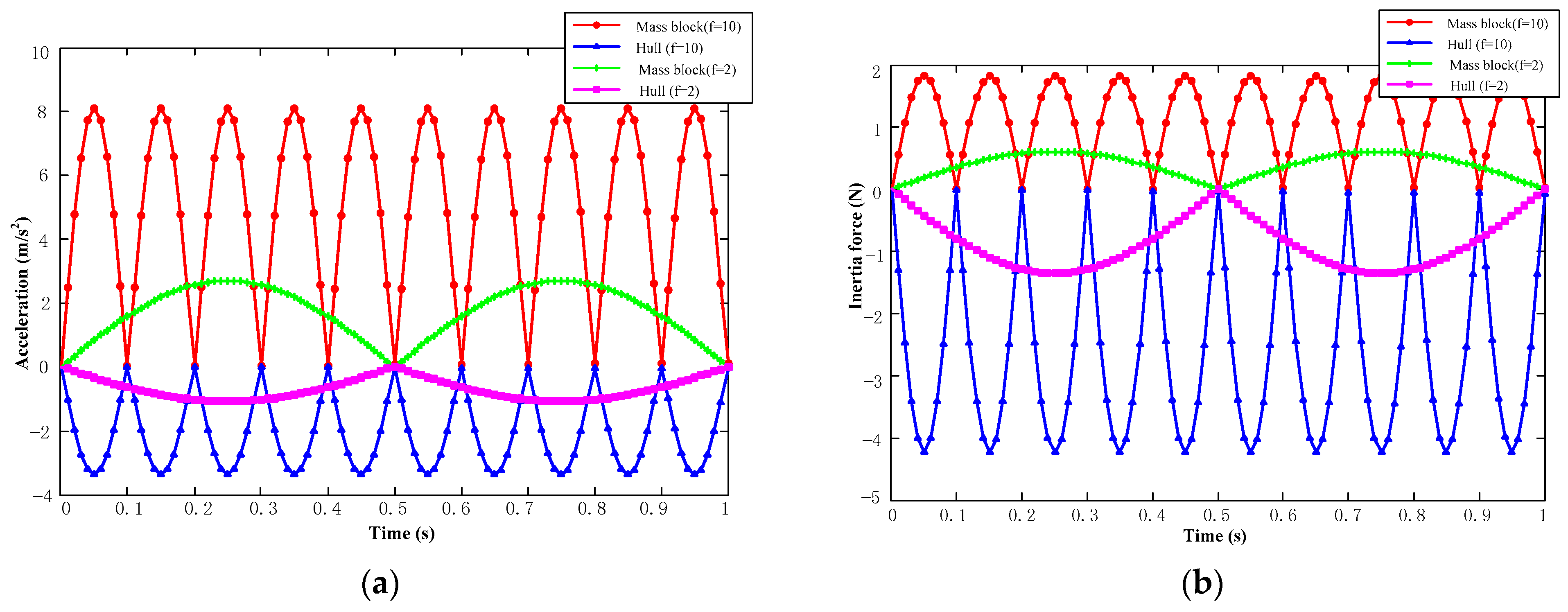
On the basis of theoretical analysis, Equation (8) was simulated by MATLAB software, and the acceleration and inertia force simulation diagrams of the mass block and base under different external interference forces are shown in Figure 3.
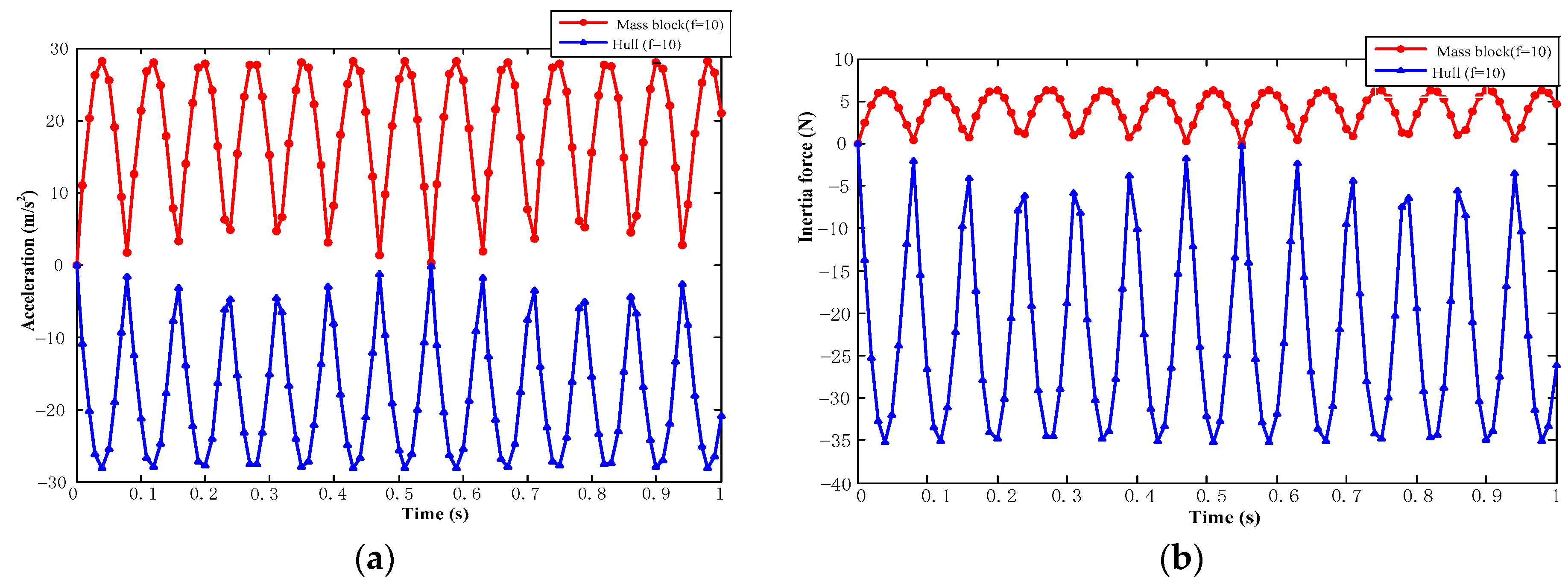
On the basis of our theoretical analysis and MATLAB simulation, the simulation was carried out by ANSYS MAXWELL2D software. Figure 4 is a nephogram of the magnetic field distribution of the electromagnetic coil. This simulation models the magnitude of the acceleration and inertia force of the mass block in the z-axis direction when voltages at frequencies of 2 Hz and 10 Hz and an amplitude of 1.25 V were applied to the upper right electromagnetic coil, respectively. Figure 5 showssimulation diagrams of the acceleration and inertia force of the mass block under different external interference forces.

2.4. Mechanical Analysis of Double Mass Block of EMS Inertial Stabilizer

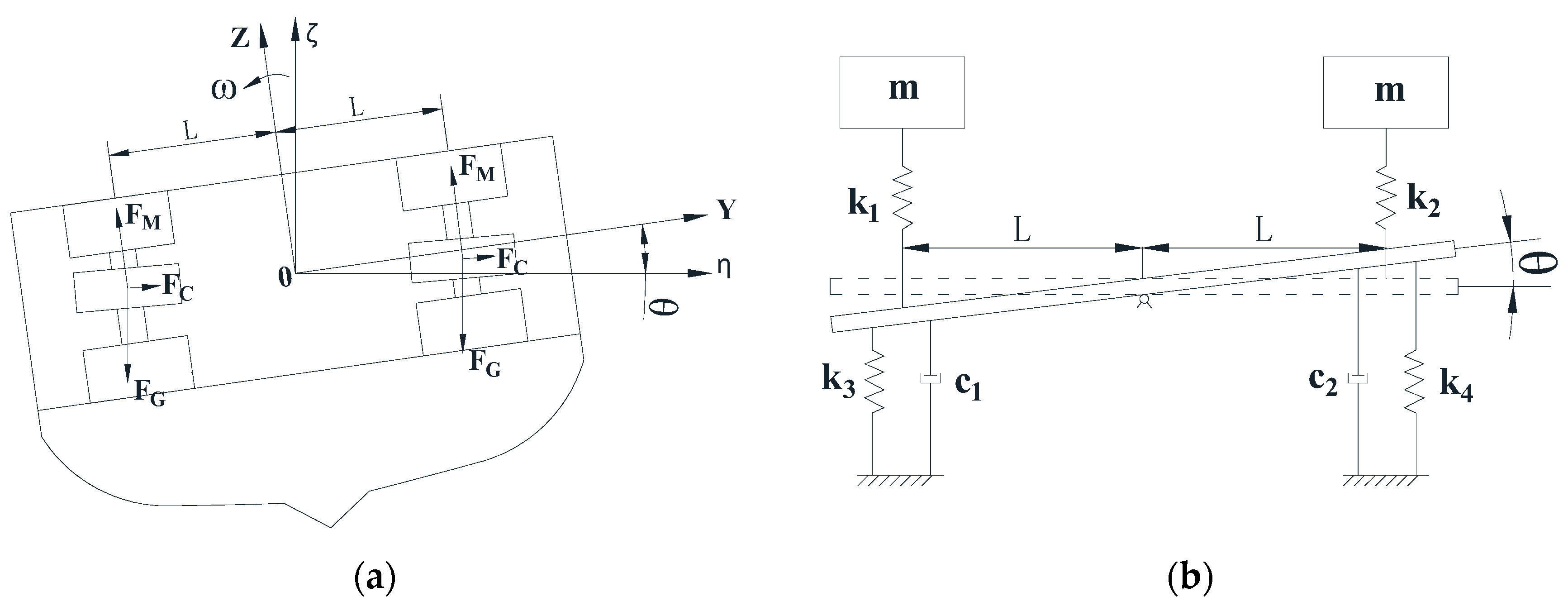
Based on the mechanical analysis of the single mass block on the right side of the EMS inertial stabilizer, our ultimate goal is to analyze the mechanical characteristics of the whole EMS inertial stabilizer, that is, the double mass block. It is still assumed that the ship would roll counterclockwise when the ship is subjected to external interference forces such as sea waves with counterclockwise F s i n ω t in the rolling direction. It is assumed that the rolling angle is θ, the displacement of the left mass block in the vertical direction is x 1 , and the displacement of the right mass block in the vertical direction is x 2 , as shown in Figure 6. The dynamic model between the mass blocks on both sides and the whole ship can be described as:
The equation of motion from the above figure is as follows:
{ J θ ¨ ( t ) = F L s i n ω t c 1 L 2 θ ˙ ( t ) k 1 L [ L θ ( t ) x 1 ( t ) ] k 3 L 2 θ ( t ) c 2 L 2 θ ˙ ( t ) k 2 L [ L θ ( t ) x 2 ( t ) ] k 4 L 2 θ ( t ) m x ¨ 1 ( t ) = k 1 [ L θ ( t ) x 1 ( t ) ] m x ¨ 2 ( t ) = k 2 [ L θ ( t ) x 2 ( t ) ]
In Equation (9), J is the moment of inertia of the ship rolling, c 1 and c 2 are the damping of the left and right sides of the ship and water, respectively, k 1 and k 2 are the support stiffness coefficients between the left and right electromagnets and the mass block, respectively, k 3 and k 4 are the support stiffness coefficients between the left and right sides of the ship and water, respectively, and m is the mass of the anti-rolling mass blocks on the left and right sides. This is simplified by Equation (9):
{ J θ ¨ ( t ) + ( c 1 + c 2 ) L 2 θ ˙ ( t ) + ( k 1 + k 2 + k 3 + k 4 ) L 2 θ ( t ) k 1 L x 1 ( t ) k 2 L x 2 ( t ) = F L s i n ω t m x ¨ 1 ( t ) k 1 L θ ( t ) + k 1 x 1 ( t ) = 0 m x ¨ 2 ( t ) k 2 L θ ( t ) + k 2 x 2 ( t ) = 0
Equation (10) is expressed in a matrix as follows:
[ J m m ] [ θ ¨ ( t ) x ¨ 1 ( t ) x ¨ 2 ( t ) ] + [ ( c 1 + c 2 ) L 2 ] [ θ ˙ ( t ) x ˙ 1 ( t ) x ˙ 2 ( t ) ] [ ( k 1 + k 2 + k 3 + k 4 ) L 2 k 1 L k 2 L k 1 L k 1 0 k 2 L 0 k 2 ] [ θ ( t ) x 1 ( t ) x 2 ( t ) ] = [ F L s i n ω t 0 0 ]
If damping is ignored, set θ = ϑ s i n ω t , x 1 = X 1 s i n ω t , x 2 = X 2 s i n ω t , substituted into the above equation to obtain:
{ θ ( t ) = F L ( k 1 m ω 2 ) ( k 2 m ω 2 ) s i n ω t m 2 ω 4 [ ( k 1 + k 2 + k 3 ) L 2 J ω 2 ] m ω 2 [ ( 2 k 1 k 2 + k 1 k 3 + k 2 k 3 ) L 2 J k 1 ω 2 J k 2 ω 2 ] + k 1 k 2 k 3 L 2 J k 1 k 2 ω 2 x 1 ( t ) = F L ( k 2 m ω 2 ) s i n ω t m 2 ω 4 [ ( k 1 + k 2 + k 3 ) L 2 J ω 2 ] m ω 2 [ ( 2 k 1 k 2 + k 1 k 3 + k 2 k 3 ) L 2 J k 1 ω 2 J k 2 ω 2 ] + k 1 k 2 k 3 L 2 J k 1 k 2 ω 2 x 2 ( t ) = F L ( k 1 m ω 2 ) s i n ω t m 2 ω 4 [ ( k 1 + k 2 + k 3 ) L 2 J ω 2 ] m ω 2 [ ( 2 k 1 k 2 + k 1 k 3 + k 2 k 3 ) L 2 J k 1 ω 2 J k 2 ω 2 ] + k 1 k 2 k 3 L 2 J k 1 k 2 ω 2
In Equation (12), k 1 and k 2 are the supporting stiffness coefficients between the left and right electromagnets and the mass block, respectively. Because the left and right structures of the ship are symmetrical, the displacement of the left and right mass blocks from the equilibrium position is basically the same under the action of external disturbance force, so k 1 k 2 . The expression of the support stiffness coefficient k 1 = N 2 A μ 0 i 0 U g 0 2 d i d x + N 2 A μ 0 i 0 U 2 g 0 3 of the single mass block is basically the same as that in Section 2.2, from the single mass block mechanical analysis of the magnetic suspension inertial stabilizer, which is expressed by k 1 here, where i 0 U is the current of the electromagnet at the equilibrium position of the mass block. After the ship size is determined, k 3 and k 4 are both constants. Equation (12) can be simplified as:
{ θ ( t ) = F L ( k 1 m ω 2 ) 2 s i n ω t m 2 ω 4 [ ( 2 k 1 + k 3 ) L 2 J ω 2 ] 2 k 1 m ω 2 [ ( k 1 + k 3 ) L 2 2 J k 1 ω 2 ] + k 1 2 k 3 L 2 J k 1 2 ω 2 x 1 ( t ) = F L ( k 2 m ω 2 ) s i n ω t m 2 ω 4 [ ( 2 k 1 + k 3 ) L 2 J ω 2 ] 2 k 1 m ω 2 [ ( k 1 + k 3 ) L 2 2 J k 1 ω 2 ] + k 1 2 k 3 L 2 J k 1 2 ω 2 x 2 ( t ) = F L ( k 1 m ω 2 ) s i n ω t m 2 ω 4 [ ( 2 k 1 + k 3 ) L 2 J ω 2 ] 2 k 1 m ω 2 [ ( k 1 + k 3 ) L 2 2 J k 1 ω 2 ] + k 1 2 k 3 L 2 J k 1 2 ω 2
The acceleration of the ship and the left and right mass blocks obtained from Equation (13) is as follows:
{ θ ¨ ( t ) = F L ( k 1 m ω 2 ) 2 s i n ω t 2 k 1 m [ ( k 1 + k 3 ) L 2 2 J k 1 ω 2 ] + J k 1 2 m 2 ω 2 [ ( 2 k 1 + k 3 ) L 2 J ω 2 ] k 1 2 k 3 L 2 / ω 2 x 1 ¨ ( t ) = F L ( k 2 m ω 2 ) s i n ω t 2 k 1 m [ ( k 1 + k 3 ) L 2 2 J k 1 ω 2 ] + J k 1 2 m 2 ω 2 [ ( 2 k 1 + k 3 ) L 2 J ω 2 ] k 1 2 k 3 L 2 / ω 2 x 2 ¨ ( t ) = F L ( k 1 m ω 2 ) s i n ω t 2 k 1 m [ ( k 1 + k 3 ) L 2 2 J k 1 ω 2 ] + J k 1 2 m 2 ω 2 [ ( 2 k 1 + k 3 ) L 2 J ω 2 ] k 1 2 k 3 L 2 / ω 2

2.5. Double Mass Block Simulation of EMS Inertial Stabilizer

On the basis of theoretical analysis, MATLAB software was used to simulate the theoretical analysis results. Simulation diagrams of the acceleration and inertia forces of mass block and base under different external interference forces are shown in Figure 7.
The moment obtained by the ship to suppress rolling is J θ ¨ ( t ) . From the expression of Equation (14) θ ¨ ( t ) , except for the constants L, M, and J, which are related to the ship structure, the moment for restraining rolling is mainly related to the supporting stiffness coefficient between the electromagnet and the mass block, that is, the electromagnet current i, the rate of change of the electromagnet current i, the air gap g 0 between the electromagnet and the inertial mass block, and the rotational angular speed ω . This is completely consistent with the conclusion of the mechanical analysis of the single mass block of the EMS inertial stabilizer in Section 2.2, and the correctness of the analysis results was also obtained.

3. Influence of Nonlinear Factors on Performance of EMS Inertial Stabilizer

3.1. Theoretical Analysis and Simulation of Nonlinear Factors

From theoretical calculation and analysis, it is known that the relationship between electromagnetic force, displacement and current is nonlinear, and the farther the mass block deviates from the equilibrium position, the higher the nonlinearity. In order to accurately control the inertial mass block, it is necessary to improve the accuracy of the electromagnet to control the acceleration of the mass block. Near the balance position of the mass block, Taylor expansion is used to analyze the magnetic force. Because the influence above the third order is small, it is only reserved to the second order. We obtain:
F M = F ( g 0 ,   I 0 ) + μ 0 N 2 A I 0 2 g 0 2 ( i I 0 ) μ 0 N 2 A I 0 2 2 g 0 3 ( g g 0 ) + μ 0 N 2 A 4 g 0 2 ( i I 0 ) 2 + μ 0 N 2 A I 0 2 2 g 0 4 ( g g 0 ) 2
when the currentin the upper and lower electromagnetic coils is basically stable, and the force on the mass block in the Z coordinate direction is:
F Z = Σ F M F G c o s ω t = F ( g 0 ,   I 0 ) + μ 0 N 2 A I 0 2 g 0 2 ( i I 0 ) μ 0 N 2 A I 0 2 2 g 0 3 ( g g 0 ) + μ 0 N 2 A 4 g 0 2 ( i I 0 ) 2 + μ 0 N 2 A I 0 2 2 g 0 4 ( g g 0 ) 2 m g c o s ω t
when the mass block is in equilibrium. F ( g 0 ,   I 0 ) is equal to the mass block gravity m g , and Equation (15) is brought into Equation (16) to obtain:
F Z = m g + μ 0 N 2 A I 0 2 g 0 2 ( i I 0 ) μ 0 N 2 A I 0 2 2 g 0 3 ( g g 0 ) + μ 0 N 2 A 4 g 0 2 ( i I 0 ) 2 + μ 0 N 2 A I 0 2 2 g 0 4 ( g g 0 ) 2 m g c o s ω t
In the vicinity of the equilibrium position, the angle ω t is small, m g m g c o s ω t . In order to control the inertial mass block accurately, it is necessary to improve the response speed of the electromagnet to the control force of the mass block, and the electromagnet is an inductive load, so it is very necessary to analyze the response speed characteristics of the control force of the electromagnet. When the voltage across the electromagnet coil is equal to the driving voltage, the current in the coil changes the fastest:
d i d t = 2 g 0 ( U d i R 0 ) N 2 μ 0 A
From Equations (17) and (18), the response speed of the control force in the Z coordinate direction is:
F Z t = F Z i d i d t = N 2 i A μ 0 2 g 0 2 2 g 0 ( U d i R 0 ) N 2 μ 0 A = i ( U d i R 0 ) g 0
From Equation (19), along the vertical direction of the ship, that is, along the Z coordinate direction in Figure 2, the control force response speed is directly related to the solenoid current, the voltage across the solenoid, the coil resistance and the air gap. The electromagnetic force response speed can be controlled by controlling the coil current, adjusting the voltage at both ends of the coil, series-parallel resistance and adjusting the air gap.
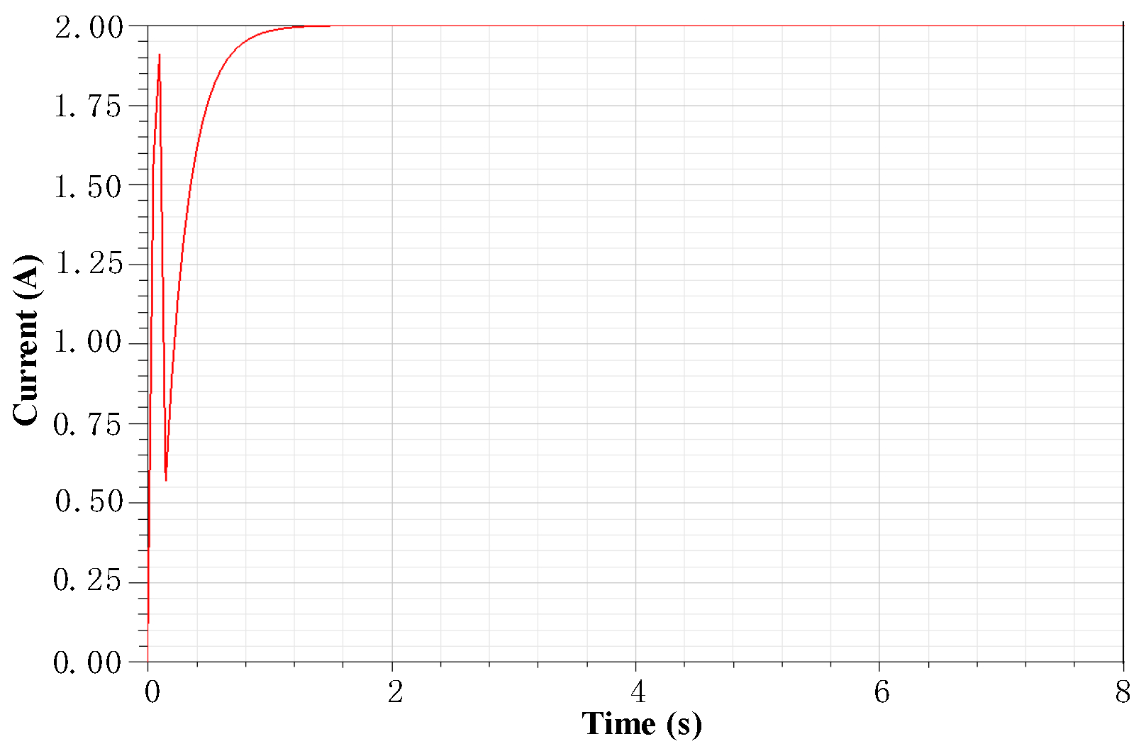
Because the electromagnetic coil is an inductive load, when the electromagnetic coil current is controlled, the frequency of the current change should not be too large, as this would cause the coil current to lag behind the voltage change. The simulation was carried out after the device was machined. The resistance of the electromagnetic coil is 0.6 Ω , and the inductance is 2.49 mH. The number of turns of the electromagnetic coil is 138. In the simulation, the voltage with an initial value of 0 Vand a maximum value of 1.2 V was applied to the coil, and the current–time curve was obtained, as shown in Figure 8. As can be seen from Figure 8, due to the influence of inductance, the coil current–time characteristic curve shows obvious nonlinearity, and the current reaches 1.8 A at 0.3 s, and then it peaks at about 1.0 s.

3.2. Time Response Characteristic Tests of Nonlinear Factors

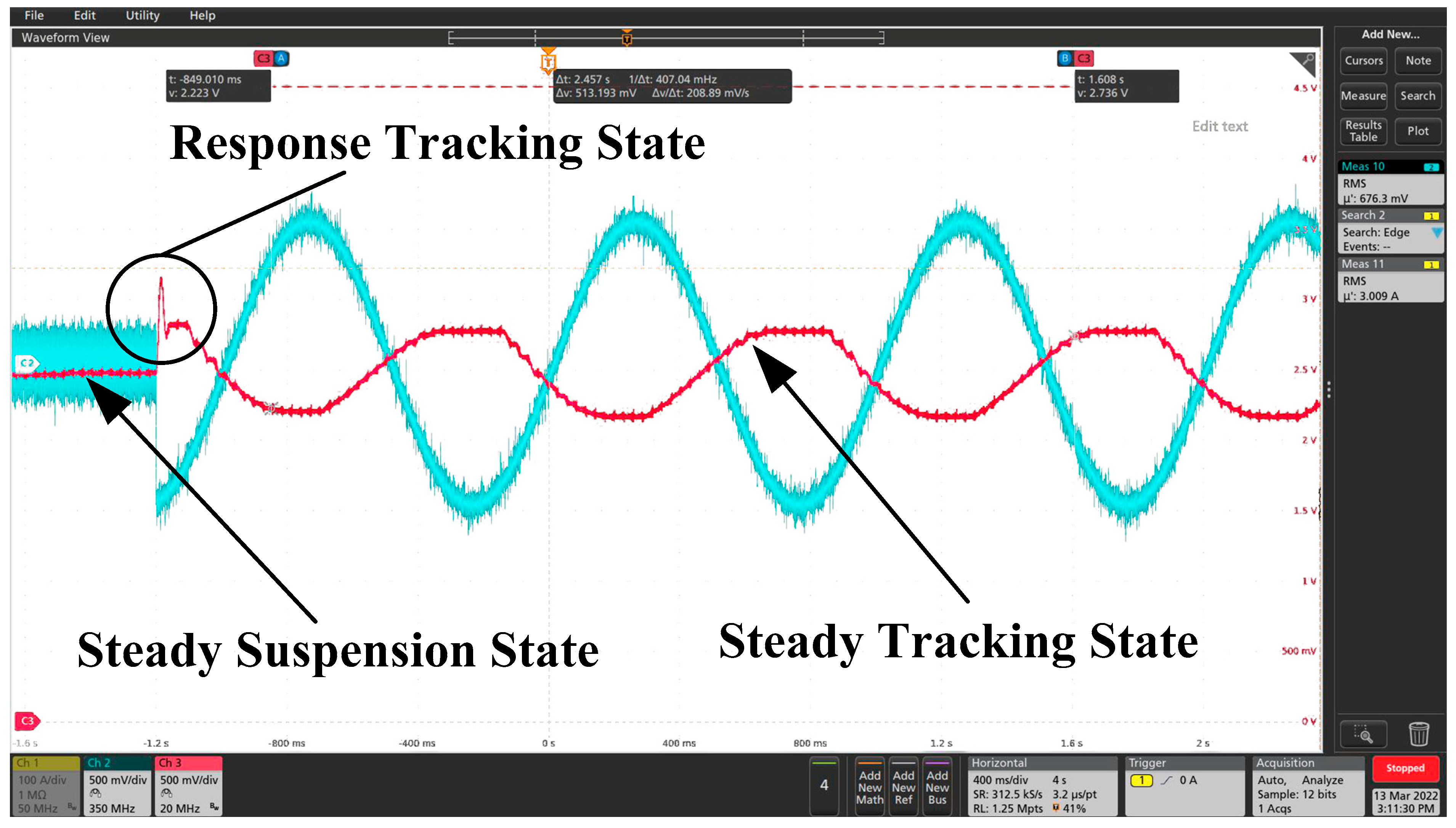
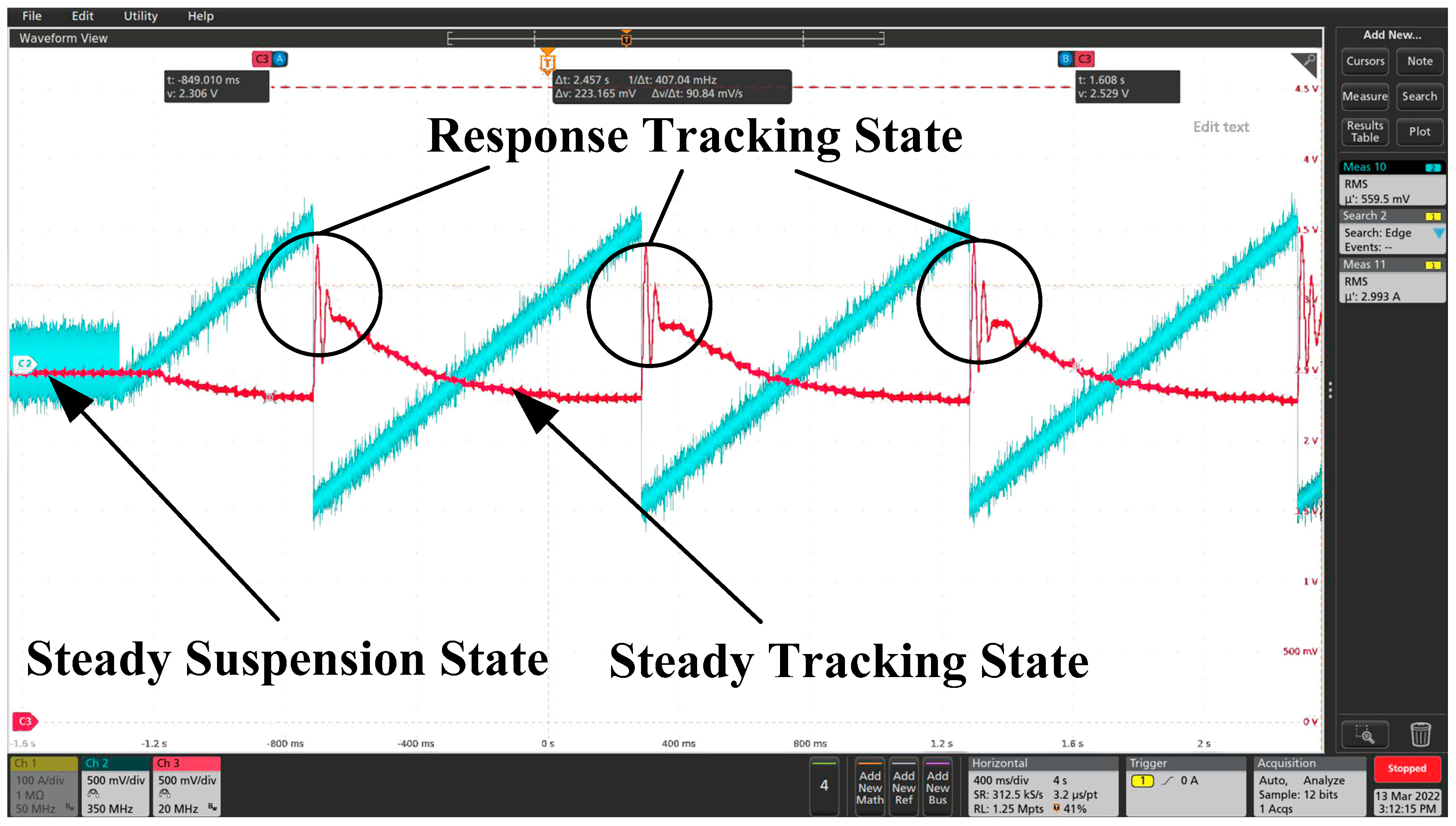
On the basis of the theoretical analysis and simulation of the nonlinear factors of the maglev inertial roll stabilizer, relevant experiments were conducted on the nonlinear factor time response characteristics of the magnetic levitation inertia reduction shaking device. The displacement–time response characteristic curves of the inertial mass block are shown in Figure 9, Figure 10, Figure 11 and Figure 12 when the excitation signal is sinusoidal signal, triangular wave signal and pulse signal, respectively. These were obtained by adding a voltage excitation signal with a frequency of 1 Hz and amplitude of 500 mV to the solenoid coil in the state of stable suspension of the inertia-decelerating mass block. The blue signal line is the excitation signal, and the red signal line is the displacement signal of the inertia reduction mass. Due to the displacement signal calibration, the displacement voltage and the excitation signal voltage values are shown to be the opposite to each other.
From Figure 9 and Figure 10, it can be seen that after adding a sinusoidal excitation signal and triangular wave excitation signal to the electromagnetic coil, the inertia reduction mass block responded quickly, and the displacement signal of the mass block produced a certain fluctuation for about 25 ms. After 25 ms fluctuation, the displacement of the mass block entered the state of the stable tracking excitation signal. In Figure 11, the excitation signal is pulsed because of the excitation signal. It can be seen from this figure that the mass block was constantly changing at the stable suspension and maximum offset position because the excitation voltage amplitude was 500 mV continuously in the pulse width range. The response time from the stable suspension position to the maximum offset position was also about 25 ms. In Figure 12, because the pulse width is small, only 100 μs, the moment the upper excitation signal was applied, the displacement signal of the mass block produced a certain fluctuation, and the time was also about 25 ms, after which it gradually entered a stable suspension state. From the simulation of Section 3.1, it was concluded that the displacement of the mass block basically reached the maximum at around 0.1 s. That is, it was suspended between the upper and lower electromagnets, and the gap between the upper and lower ones is basically the same. It can be concluded from the above tests that the response time of the magnetic levitation inertia reduction mass displacement is about 25 ms due to the nonlinear factors and the characteristics of the solenoid coil itself, and the stability and anti-interference of the whole system designed by the authors is very good.

4. Tests and Results

4.1. Experiments

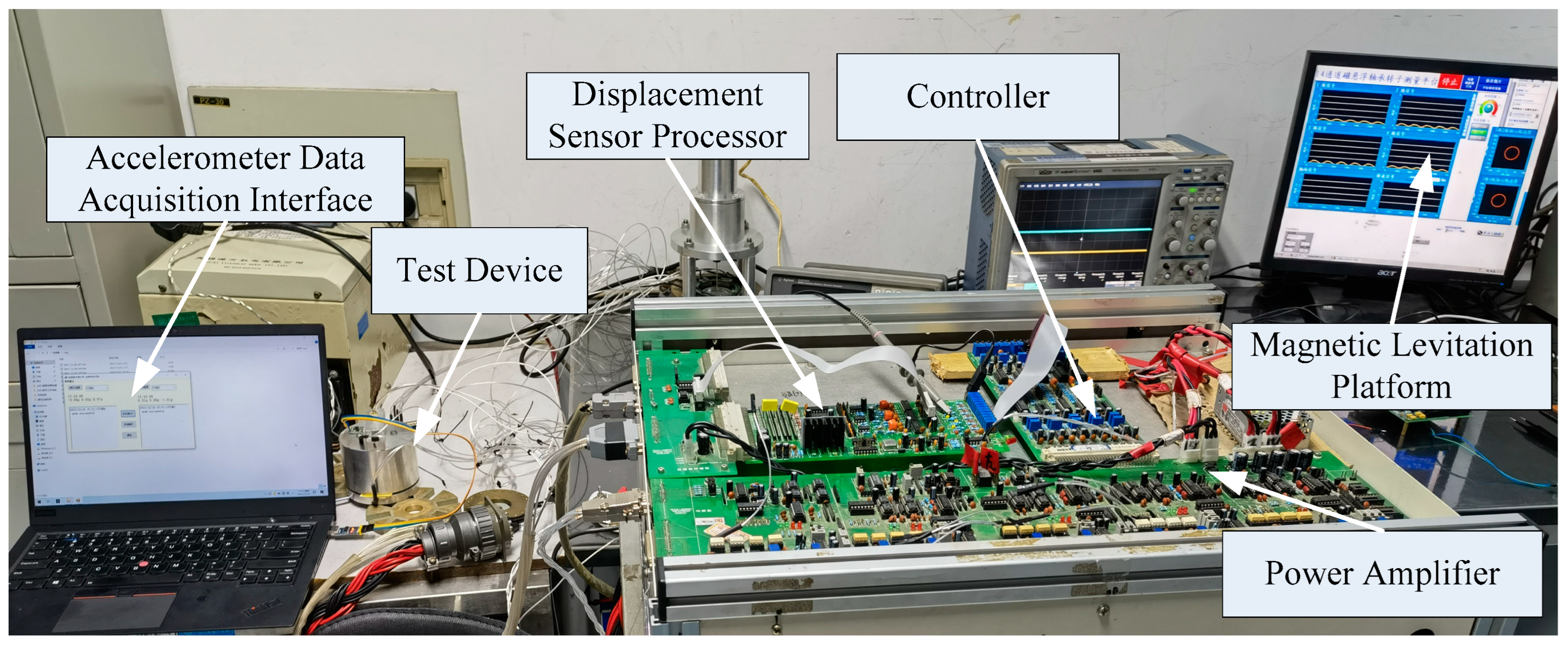
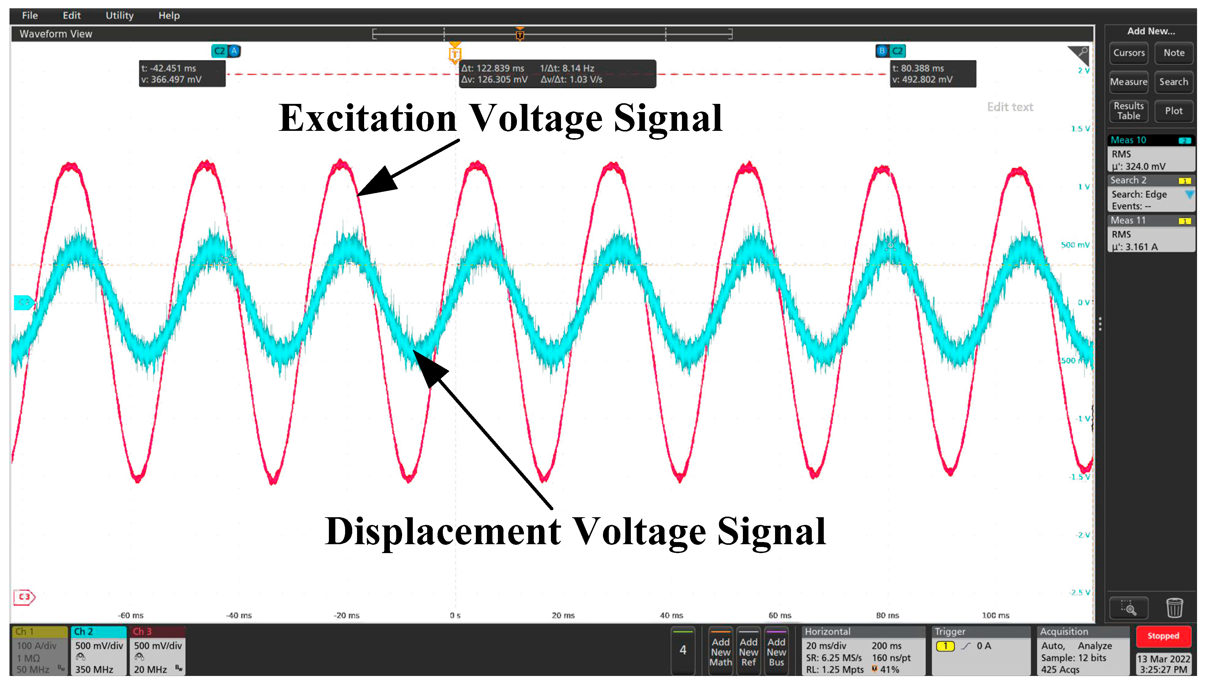
On the basis of our theoretical analysis and simulation, an EMS inertial stabilizer was manufactured. The parameters of the device are shown in Table 1. The test device diagram, the schematic block diagram of the system, the test device and signal acquisition and the excitation voltage and displacement voltage signal in the stable suspension state are shown as Figure 13, Figure 14, Figure 15 and Figure 16.
The data in Table 2 are the acceleration values of the mass block and the base at the X-axis, Y-axis and Z-Axis. They were measured by the acceleration sensor after the mass block was suspended stably, and a 1.5 V sinusoidal excitation voltage was added to the electromagnetic coil above. It can be seen from the table that the acceleration values of the mass block and the base are always relatively small at the X-axis. The acceleration value of the base at Y-axis is also small and can basically be ignored. However, due to the Coriolis force, the acceleration value of the mass block on the Y-axis is sometimes large, reaching a maximum of 0.83 g, that is, 8.13 m/s2, which is consistent with the previous theoretical analysis. As can be seen from the table, the maximum accelerations of the mass block and the base on the Z-axis are 1.05 g and 0.13 g, respectively, that is, 10.29 m/s2 and 1.27 m/s2, respectively.

4.2. Comparison between Analytical Calculation, Numerical Results and Experimental Results

Figure 17 shows the mass block acceleration values calculated by the three methods. For the first calculation method, the analytic expressions obtained were used. The second one was carried out by finite-element computation. The third one was obtained by experiments. The accuracy of the analytical calculation seems to be higher than the finite-element computation and experimental results. The numerical precision can probably be improved. One possibility is that in the finite element simulation, the performance of some parts or units is inconsistent with the real parts. It can also be seen from the comparison results that the test data are smaller than the theoretical analysis and simulation data, mainly because in the real test, the magnetic circuit is not ideal and the magnetic leakage phenomenon is common. In addition, in the theoretical analysis and simulation, the largest acceleration value appeared at about 10 Hz. In the actual test, the maximum acceleration value appeared near 12 Hz. A comparison between the results shows that the three methods are in approximate agreement. The analytical results are proved to be correct by the experimental results.

5. Conclusions

In this paper, single mass block and double mass block mechanical analyses of an EMS inertial stabilizer were carried out, and analytical models were established. Based on the mechanics analysis, the simulation was carried out using MATLAB and finite-element software. Finally, a single mass block system for an EMS inertial stabilizer was designed and tested. Our theoretical analysis, simulation and experiments show that the inertial force transmitted to the ship by the EMS inertial stabilizer is directly related to the turns of the electromagnetic coil, the coil current, the mass block and the mass of the ship. The response speed of the inertia force is directly related to the current of the solenoid, the voltage across the solenoid, the resistance of the solenoid and the air gap. The electromagnetic force response speed can be controlled by controlling the coil current, adjusting the voltage at both ends of the coil, series-parallel resistance and adjusting the air gap. The inductance of the solenoid would also increase the nonlinearity of the system. Hence, the conclusion can be drawn that the inertia force obtained by the hull base is related to the electromagnet current i , the change rate of the electromagnet current i , the air gap g 0 between the electromagnet and the inertial mass block, and the rotational angular velocity ω . It was proved by experiments that as long as the external excitation frequency is equal to or approximately equal to the natural frequency of the maglev mass block, a large inertia force will be acquired by the mass block. The hull can maintain stability, and the ship roll reduction target can be achieved in all working conditions (all kinds of speed, all kinds of waves).

Author Contributions

Investigation, L.X.; Software, C.J.; Writing—original draft, S.G. All authors have read and agreed to the published version of the manuscript.

Funding

This project is supported by National Natural Science Foundation of China (51875275), the “Six Talent Summit” -high-level talent project in Jiangsu Province (JNHB-041) and the scientific research fund incubation project of Jinling Institute of Technology (jit-fhxm-201915).

Institutional Review Board Statement

The study was conducted in accordance with the Declaration of Helsinki, and approved by the Institutional Review Board (or Ethics).

Informed Consent Statement

Informed consent was obtained from all subjects.

Data Availability Statement

Data supporting reported results can be found in the author’s doctoral thesis.

Conflicts of Interest

The authors declare no conflict of interest.

References

  1. Prasad, V.; Tiwari, R. Identification of Speed-dependent Active Magnetic Bearing Parameters and Rotor Balancing in High-speed Rotor Systems. J. Dyn. Syst. Meas. Control 2019, 141, 041013. [Google Scholar] [CrossRef]
  2. Chaowu, J.; Yili, Z.; Longxiang, X.; Lei, J.; Laishui, Z. Dynamics of Rotor Drop on New Type Catcher Bearing. Trans. Nanjing Univ. Aeronaut. Astronaut. 2014, 31, 70–77. [Google Scholar]
  3. Moreira, A.B.B.; Thouverez, F. Influence of Blade Flexibility on the Dynamic Response Simulation of a tur-bomolecular Pump on Magnetic Bearings. J. Eng. Gas Turbines Power 2020, 142, 041004. [Google Scholar] [CrossRef]
  4. Hawkins, L.; Prosser, D.; Filatov, A.; Prosser, D. Test Results and Analytical Predictions for Rotor Drop Testing of an Active Magnetic Bearing Expander/Generator. J. Eng. Gas Turbines Power 2007, 129, 522–529. [Google Scholar] [CrossRef] [Green Version]
  5. Xing, M.; Wei, T. Autobalancing of High-speed Rotors Suspended by Magnetic Bearings Using LMS Adaptive Feedforward Compensation. J. Vib. Control 2014, 20, 1428–1436. [Google Scholar] [CrossRef]
  6. Cong, P.; Jinji, S.; Cunxiao, M.; Jiancheng, F. A novel Cross-feedback Notch Filter for Synchronous Vibration Suppression of an MSFW with Significant Gyroscopic effects. IEEE Trans. Ind. Electron. 2017, 64, 7181–7190. [Google Scholar]
  7. Sotelo, G.G.; de Andrade, R.; Dias, D.H.N.; Ferreira, A.C.; Costa, F.; Machado, O.J.; de Oliveira, R.A.H.; Santos, M.D.A.; Stephan, R.M. Tests with One Module of the Brazilian Maglev-cobra Vehicle. IEEE Trans. Appl. Supercond. 2013, 23, 3601204. [Google Scholar] [CrossRef]
  8. De Oliveira, R.A.H.; Stephan, R.M.; Ferreira, A.C. Optimized Linear Motor for Urban Superconducting Magnetic Levitation Vehicles. IEEE Trans. Appl. Supercond. 2020, 30, 1–8. [Google Scholar] [CrossRef]
  9. Takeshi, M.; Masaya, T.; Kishita, D.; Hirakawa, K. Vibration Isolation System Combining Zero-power Magnetic Suspension with Springs. Control. Eng. Pract. 2007, 15, 187–196. [Google Scholar]
  10. Carrella, A.; Brennan, M.J.; Waters, T.P.; Shin, K. On the Design of a High-static-low-dynamic Stiffness Isolator Using Linear Mechanical Springs and Magnets. J. Sound Vib. 2008, 315, 712–720. [Google Scholar] [CrossRef]
  11. Nan, Q.; Jun, Z.; Lei, W.; Wang, B.; Li, J.; Ren, Y.; Deng, Z. Dynamic Vibration Characteristics of HTS Levitation Systems Operating on a Permanent Magnet Guideway Test Line. IEEE Trans. Appl. Supercond. 2017, 27, 3601405. [Google Scholar]
  12. Wuyang, L.; Nan, Q.; Yu, R.; Yanxing, L.; Jun, Z.; Zigang, D. An Onboard Measurement System for Studying the Dynamic Running Characteristics of HTS Maglev. IEEE Trans. Appl. Supercond. 2018, 28, 3601005. [Google Scholar]
  13. Hoon, P.C.; Chang, P.H.; Cho, H.W.; Moon, S.J.; Chung, T.Y. Development of a Small Maglev-type Antirolling System. Rev. Sci. Instrum. 2010, 81, 056102. [Google Scholar]
  14. Hirakawa, Y.; Hirayama, T.; Kakizoe, K.; Takayama, T.; Funamizu, S.; Okada, N.; Yamane, A. Sea Trial of Prototype Vertical Weight Stabilizer (VWS) Anti-rolling System for Small Ships. J. Mar. Sci. Technol. 2014, 19, 292–301. [Google Scholar] [CrossRef]
  15. Gaoming, Q.; Hongyu, Q. The Invention Relates to a Marine Permanent Magnetic Levitation Anti-swing Automatic Balance System and Its Application. C.N. Patent 201810771460.2, 13 November 2018. [Google Scholar]
  16. Li, S.; Ding, F.; Zhang, D.; Shan, T.; Chi, B.; Bai, W.; Yang, W. Ship Moment Gyro Rolling Control Device and Rolling Control Method. C.N. Patent 201210480310.9, 16 November 2012. [Google Scholar]
  17. Sumei, G.; Quanyong, J.; Chaowu, J. Support characteristics and application of permanent magnet suspension active mass drive system. Int. J. Appl. Electromagn. Mech. 2021, 67, 83–96. [Google Scholar]
  18. Sumei, G.; Longxiang, X.; Chaowu, J.; Qianwei, C. Adaptive Magnetic Suspension Anti-rolling Device Based on Frequency Modulation. Open Phys. 2020, 18, 189–198. [Google Scholar]
  19. Yefa, H. Basic Theory and Application of Magnetic Bearing; China Machine Press: Beijing, China, 2006. [Google Scholar]
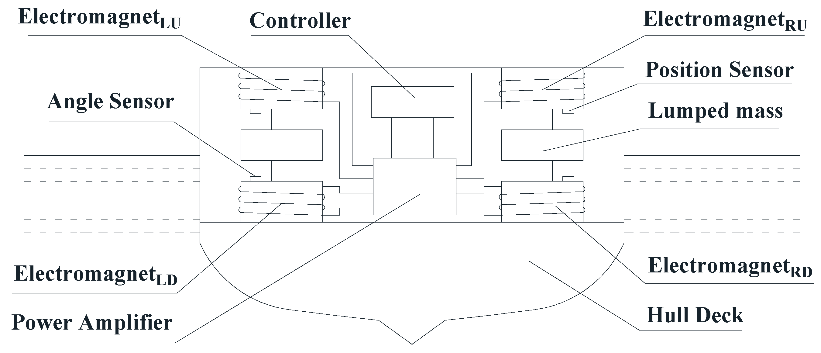
Figure 1. Structural diagram of EMS inertial stabilizer.
Applsci 12 05304 g001
Figure 2. Mechanical analysis diagram of inertia anti-rolling mass block.
Applsci 12 05304 g002
Figure 3. Acceleration and inertia force simulation diagram of mass block and base. (a) Acceleration diagram; (b) inertia force diagram.
Applsci 12 05304 g003
Figure 4. When the frequency is 10 Hz, the magnetic field distribution nephogram at 1 s. (a) Schematic diagram and semisectional view; (b) finite element diagram.
Applsci 12 05304 g004
Figure 5. Acceleration and inertia force simulation diagrams of mass block at different frequencies. (a) Acceleration diagram; (b) inertia force diagram.
Applsci 12 05304 g005
Figure 6. Anti-rolling mass block and ship overall model diagram. (a) Schematic diagram of ship cross section; (b) ship mechanical model.
Applsci 12 05304 g006
Figure 7. Acceleration and inertia force simulation diagram of mass block and base. (a) Acceleration diagram; (b) inertia force diagram.
Applsci 12 05304 g007
Figure 8. Influence of coil inductance on current–time characteristics of electromagnet.
Applsci 12 05304 g008
Figure 9. Displacement–time response characteristics curve under sinusoidal excitation signal.
Applsci 12 05304 g009
Figure 10. Displacement–time response curve under triangular wave excitation signal.
Applsci 12 05304 g010
Figure 11. Displacement–time response curve under pulse excitation signal (pulse width: 200 ms).
Applsci 12 05304 g011
Figure 12. Displacement–time response curve under pulse excitation signal (pulse width: 100 μs).
Applsci 12 05304 g012
Figure 13. Test device diagram. (a) Parts; (b) assembled device.
Applsci 12 05304 g013
Figure 14. The schematic block diagram of the system.
Applsci 12 05304 g014
Figure 15. Test device and signal acquisition.
Applsci 12 05304 g015
Figure 16. Excitation voltage and displacement voltage signal in stable suspension state.
Applsci 12 05304 g016
Figure 17. Comparison of theoretical analysis, simulation and test results of mass acceleration. Red lines represent the analytical calculation, and blue lines are the numerical results by ANSYSMAXWELL2D. Pink lines are the experimental results.
Applsci 12 05304 g017
Table 1. Parameters of EMS inertial stabilizer.
ParameterValue
Cross-sectional area of electromagnet core A / mm 2 290
Air permeability μ 0 / ( H · m 1 ) 4 π × 10 7
Number of turns of electromagnetic winding N138
Diameter of enameled wire mm21
Electromagnetic winding inductance L/mH2.49
Air gap g 0 / mm 1.5
Mass of inertia anti-rolling mass block m / g 225
Base mass M / g 1250
Acceleration sensorJY61
Displacement sensorAuthor’s own design
Table 2. Part of the accelerometer data.
Hull AccelerationMass Block Acceleration
X-AxisY-AxisZ-AxisX-AxisY-AxisZ-Axis
−0.03 g−0.05 g−0.04 g−0.11 g0.06 g0.56 g
−0.04 g−0.01 g−0.05 g−0.10 g−0.19 g0.61 g
−0.01 g0.00 g−0.07 g0.09 g0.15 g0.25 g
−0.01 g0.01 g−0.02 g0.10 g−0.04 g0.18 g
0.00 g0.02 g−0.02 g−0.10 g0.06 g0.08 g
0.02 g0.06 g−0.03 g0.05 g0.09 g0.39 g
−0.04 g−0.03 g−0.13 g0.04 g−0.83 g0.98 g
−0.02 g0.05 g−0.04 g0.05 g0.03 g0.13 g
−0.08 g−0.01 g−0.01 g0.09 g0.04 g0.16 g
−0.08 g0.00 g−0.01 g0.12 g0.14 g0.05 g
−0.03 g0.05 g−0.06 g0.19 g−0.03 g0.53 g
−0.05 g0.00 g−0.02 g−0.01 g0.16 g0.63 g
−0.10 g−0.04 g−0.09 g0.05 g−0.01 g1.05 g
−0.04 g0.03 g−0.01 g−0.22 g0.02 g0.16 g
−0.06 g0.03 g−0.01 g−0.23 g0.04 g0.30 g
−0.01 g0.07 g−0.03 g0.05 g0.07 g0.28 g
Note: g in this table is the acceleration of gravity. The data werecollected at intervals of 0.01 s.
Publisher’s Note: MDPI stays neutral with regard to jurisdictional claims in published maps and institutional affiliations.