Abstract
Trenchless rehabilitation lining can be divided into flexible solid wall lining structures, rigid lining structures and rigid–flexible composite lining structures. This paper reviews the research status of the design theory of trenchless rehabilitation lining pipes, analyzes the theory of rigid–flexible composite lining structures, and points out that the value of the factor determined from non-grouting angle K1 is not clear in the design formula of the rigid–flexible composite lining structure mentioned in the ASTM ‘Standard Practice for Installation of Machine Spiral Wound Poly (Vinyl Chloride) (PVC) Liner Pipe for Rehabilitation of Existing Sewers and Conduits (ASTM F 1741)’. The value of K1 was obtained by the numerical analysis method with MATLAB software. Through the analysis of the variation trend of the K1 value, it is concluded that the design formula in the ASTM standard is only applicable to the case of incomplete grouting filling between the original pipe and the lining pipe, and is not applicable to the composite lining pipe with complete grouting filling. Finally, the explicit formula of the non-grouting angle is obtained by fitting, which is more convenient to use.
1. Review on Design Theory of Lining for Trenchless Pipeline Rehabilitation
Trenchless pipeline rehabilitation technology is a construction technology for the installation of lining pipes in existing pipelines, without excavation [1]. The commonly used trenchless pipeline rehabilitation technology can be divided into four categories. The first category is the repair process of inserting the lining pipe inside the pipeline based on the change in the physical properties of the pipe, including shrinkage lining repair technology, folding lining repair technology and in situ thermoplastic lining repair technology. The second category is the repair process of in situ curing lining inside the pipeline based on chemical changes in the materials, mainly including in situ curing lining repair technology, which can be divided into thermal curing, steam curing and UV curing, according to the curing type. The third category is the repair process of using profile or sheet material to install a flexible lining pipe inside the pipeline, and then filling mortar between the lining pipe and the original pipeline to form a composite lining, mainly including mechanical spiral wound lining repair technology, segment lining repair technology, gasket repair technology and short pipe lining repair technology. The fourth category is the repair process based on spraying molding, including resin spraying technology and mortar spraying technology.
In the above repair processes, the first and second repair processes and the resin spraying repair lining in the fourth repair process belong to the flexible solid wall lining structure. The mortar spraying repair lining pipe in the fourth type of repair method belongs to the rigid lining structure. In the third type of repair process, mortar is needed to be filled and compacted between the lining pipe and the original pipe, so it belongs to the rigid–flexible combined lining structure.
In previous studies, much research has been conducted on the design of flexible solid wall lining structures. Based on the linear elastic theory of small displacement, Timoshenko and Gere [2] deduced the critical external pressure buckling strength formula of free rings according to the flexural differential equation of bending slender rods. The free ring buckling theory has been widely used in the structural design of flexible pipes, and the formula is as follows:
where D is the average pipe diameter; I is the moment of inertia of the cross section; is Poisson’s ratio; Pcr is the critical buckling pressure; E is the elastic modulus.
Boot [3,4,5] assumes that the total potential energy of the lining during buckling is equal to the work conducted by the strain energy of the lining and the external hydrostatic pressure. At the same time, it is assumed that the circumferential axial force on the whole ring is a constant and the shape of the deformation section of the lining is a chord function. Then, the semi-analytical solution of critical buckling of the lining with annular clearance is obtained. Li [6] studied the buckling performance of the lining with reduced local wall thickness due to corrosion under uniform external pressure, and established an analytical formula for the buckling strength of the lining with uneven thickness under external pressure, according to the classical Glock theory. Rueda et al. [7] studied the stress–strain relationship curve of the material after repairing the pipeline with high-density polyethylene (HDPE) lining, and studied the buckling failure characteristics through numerical simulation. On the basis of this, the corresponding calculation formula of buckling strength was proposed. Vasilikis and Karamanos [8,9] used numerical simulation to consider the influence of the initial annular gap and fold on the buckling strength of the lining. Finally, the calculation method of buckling strength of thin-walled lining was proposed. They also carried out a bending test and a finite element simulation of the lining with wrinkles, and found that the shape of the bending failure of the lining is almost identical. Vasilikis and Karamanos [10] also proposed a plastic hinge model, which assumes that (1) the thin shell is an elastic body, and the buckling deformation occurs at a certain arc position without shrinkage or elongation, and (2) the two endpoints of the arc are moving plastic hinges, and the center points of the two are static plastic hinges. According to the above assumptions, they put forward the corresponding theoretical calculation formula. Chunqing Lu et al. [11] studied the buckling behavior of stainless steel thin lining under negative pressure after trenchless repair of an urban water supply network. Finally, an improved lining buckling prediction model (enhanced model) is proposed. In addition, the design of flexible solid-wall liner is stipulated in the ASTM series standards [12,13,14,15,16,17], which is divided into structural repair and semi-structural repair.
For the study of rigid lining structures, Kong Yaozu [18] proposed the basic principle of rigid lining structure design according to the different stress states of the old pipeline, and established the theoretical model of lining design. Zhang Haifeng [19] carried out design research according to the limit state design method, according to different failure modes and structural models of pipelines. Zhao Yahong et al. [20] found that after the interior of the concrete pipe is repaired by cement mortar, if the shear strength of the old and new interface is low, the old and new interface of the composite structure will strip under the external loads, which will affect the bearing capacity of the structure. In the literature [21,22,23,24], the bearing capacity of the pipeline repaired by mortar spraying lining was studied through experiments, indicating that the mortar spraying rigid lining significant improved the bearing capacity of the original pipeline.
For rigid–flexible composite lining structure design, J.H. Wang et al. considered the hydrostatic buckling failure of a noncircular composite liner with an arched invert installed in the sewer pipe. An equation was derived for the buckling of the invert liner, and its application procedure was proposed [25]. For circular pipes, the design method in the ASTM ‘Standard Practice for Installation of Machine Spiral Wound Poly (Vinyl Chloride) (PVC) Liner Pipe for Rehabilitation of Existing Sewers and Conduits (ASTM F 1741)’ [26] is mainly used. China’s national industry standard ‘Technical specification for trenchless rehabilitation and renewal of urban sewer pipeline (CJJ/T210)’ [27] also refers to the ASTM standard for the design of the mechanical spiral winding method and the segment lining method.
2. Theoretical Basis of Rigid–Flexible Composite Lining Structure Design
The design theory of rigid–flexible composite lining structures is based on the buckling theory of rings under uniform compression. For the rigid–flexible composite lining structure, the rigid structure is formed by filling mortar in the gap between the flexible lining pipe and the original pipeline. However, due to the long longitudinal length of the pipeline, it is often difficult to ensure that the gap between the flexible lining pipe and the original pipeline is fully filled and compacted in the construction process of mortar filling. Therefore, there are often gaps between the flexible liner and the original pipeline, as shown in Figure 1. In this case, the two ends of the flexible liner at the gap can be regarded as fixed in the rigid filling slurry. Therefore, it is reasonable to consider that the theoretical basis of rigid–flexible composite lining structure design is the uniform compression arch buckling theory with fixed ends.
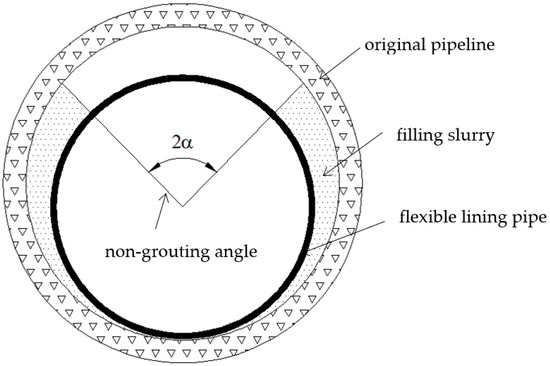
Figure 1.
Schematic diagram of rigid–flexible composite lining structure.
The theoretical schematic diagram of uniform compression arch buckling with fixed ends is shown in Figure 2. Both ends of A and B are fixed ends, and the angle between A and B is 2α. The arch is subjected to uniform pressure P. Assuming that after buckling of the arch, there is not only horizontal pressure S, but also direct shear force Q at the midpoint C, and the arch is regarded as the cable curve of uniform pressure and is used to represent the radial displacement of the center, then the bending moment M of any cross section m determined by angle is as follows [2]:

Figure 2.
Schematic diagram of theoretical model of rigid–flexible composite lining structure design.
The bending differential equation of the circular slender rod shown in Figure 2 is as follows:
According to Formulas (2) and (3), Formula (4) can be obtained.
Formula (4) can also be expressed as Formula (5).
By replacing with K12, Formula (5) may be expressed as Formula (6).
The ordinary solution of the equation is shown as Formula (7).
The conditions determining constants A and B and shear force Q are shown as Formulas (8) and (9).
When B is zero, Formula (8) can be satisfied, so Formulas (10) and (11) can be obtained from Formula (9).
Through Formulas (10) and (11), Formula (12) can be obtained.
From Formula (12), the value of K1 can be obtained, which is brought into formula , and the buckling critical value of uniform compression arch with fixed ends is shown as Formula (13).
3. Design Formula of Rigid–Flexible Composite Lining Structure in ASTM Standard
The design of trenchless rehabilitation lining pipes for drainage pipelines is divided into semi-structural repair and structural repair. The design of rigid–flexible composite lining structures in the ASTM standard [26] is based on Formula (13). The long-term creep effect of the pipeline is considered by changing the elastic modulus into the long-term elastic modulus EL, and the influence of geometric defects in the lining pipe is considered by introducing the ellipticity reduction factor C [28]. Finally, Formula (14) is obtained.
where EL is the long-term elastic modulus of the liner (MPa); I is the rotational inertia of the liner (mm4/mm); ELI is the stiffness coefficient of the liner (MPa·mm3); D is the average diameter of the liner (mm)); D0 is the outer diameter of the lining pipe (mm); h is the height of the strip profile (mm); is the distance from the inner surface of the strip to the neutral axis of the strip (mm); Pcr is the water pressure at the pipe bottom (MPa); C is the ellipticity reduction factor; q is the ellipticity of the original pipeline (%), but if the ellipticity cannot be measured, take 2%; K1 is the factor determined from the filling angle without grouting.
The value of K1 in Formula (14) needs to be calculated by Formula (12). However, the relation between K1 and α in Formula (12) is not clear, which is not conducive to the use of designers.
4. Solution of K1 Value
Formula (12) is difficult to solve by conventional mathematical methods. Therefore, the dichotomy method is used to find the solution of the value of K1. When using dichotomy, the function f, as shown in Formula (16), must be established, then the solution of K1 needs to be solved, when f = 0.
In order to solve the value of K1 by dichotomy, a monotone interval needs to be given, and then iteration is carried out. Since the function f is not a monotone function, in order to ensure its correctness, we should give as many monotone intervals as possible for multiple roots [29]. According to the formula and its physical meaning, the definition domain of K1 is (1, ∞). Therefore, in order to find the value of K1, 18 intervals, (1.1, 1.6), (1.6, 2.1) … (59.6, 60.1), are given in the solving process.
Because α is also an uncertain parameter in Formula (16), an α value must be given when solving K1. According to Figure 1, the definition domain of α is (0, π); therefore, α is given and varies from π/36 (5°) to π (180°) by every interval of π/72 (2.5°).
According to the above monotonic interval and values of α, Formula (16) is solved by MATLAB software programming, and the obtained numerical points are plotted as the distribution map of K1 value, as shown with a square marker in Figure 3. Figure 3 shows that each α corresponds to multiple K1 values. Multiple sets of curves with similar shapes can be obtained by connecting each K1 value with a line, reflecting that the function f is a set of periodic functions.
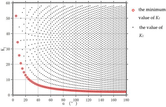
Figure 3.
Distribution of K1 relative to α calculated by MATLAB.
According to the calculation results of dichotomy, when α is 180°, there is no grouting between the liner and the original pipeline, and the minimum value of K1 is 2.0. Substituting it into Equation (14), Formula (17) can be obtained.
Formulas (1) and (17) of the critical buckling bearing capacity of an infinite-length independent tube under hydrostatic external pressure are similar in form and have the same numerical parameters—24. Therefore, the minimum K1 value corresponding to each α, that is, the set of values marked by the red circle in Figure 3, should be taken as the solution of Formula (16). The dichotomy calculation results of K1 are shown in Table 1.

Table 1.
Dichotomy calculation result of K1.
In order to verify the accuracy of the results, the data in Table 1 are substituted into Equation (16) to check the error and draw the data error curve, as shown in Figure 4. It can be observed from Figure 4 that the maximum error of the MATLAB calculation results is less than 0.0003, so the results calculated by dichotomy are relatively accurate.
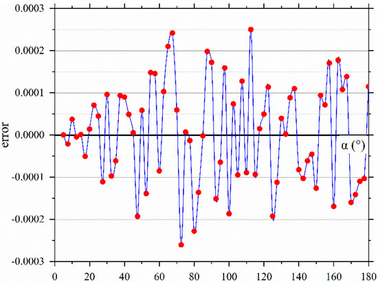
Figure 4.
The error curve calculated by MATLAB.
The nonlinear regression function is used to fit the value of Table 1. Commonly used nonlinear regression functions include the exponential function, logarithmic function, polynomial function, power function, parabolic function, hyperbolic function, and S curve function [30]. According to the data trend shown in Figure 3, the power function is selected for the fitting analysis. The regression analysis curve is shown in Figure 5.
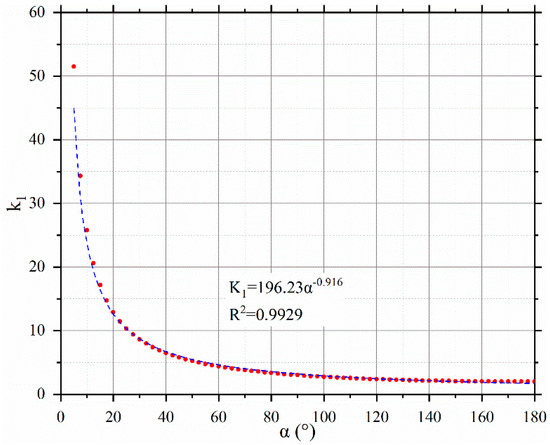
Figure 5.
Power function regression curve of K1.
It can be observed from Figure 5 that the 1/2 non-grouting angle α has a nonlinear relationship with α, and is a decreasing function. Formula (14) shows that the stiffness coefficient is also a decreasing function of K1 value, so the stiffness coefficient is an increasing function of the 1/2 non-grouting angle α. When the grouting slurry is fully filled with voids, the 1/2 non-grouting angle α tends to be zero, and the K1 value tends to be infinity. Therefore, the stiffness coefficient of the lining calculated by Formula (14) tends to be zero, and, in this case, Formula (14) will be meaningless.
Therefore, Formula (14) is only applicable to the structural design of rigid–flexible composite lining with incomplete grouting. During construction, the non-grouting angle 2α should be reasonably evaluated according to the grouting technology to design the lining structure.
5. Modification of Structural Design Formula of Rigid–Flexible Composite Lining in ASTM Standard
In order to directly reflect the relationship between the stiffness coefficient of the liner and the ½ non-grouting angle α, and make Formula (14) become the dominant formula of α, the fitting formula of K1 value should be brought into Formula (14). Because the value of K1 in Formula (14) appears in squared form, the error of value fitting is smaller than that of value fitting for Formula (14).
When grouting the gap between the original pipeline and the lining pipe, filling half of the slurry is relatively easy to achieve, and, in practice, α rarely exceeds 90°. Therefore, where , the corresponding values are re-fitted, and the power function is selected for regression fitting. The fitting formula and correlation coefficient are shown as Formula (18).
By substituting Formula (18) into Formula (14), the explicit relation between the stiffness coefficient of the liner and the 1/2 non-grouting angle α can be expressed as Formula (19).
6. Conclusions
In this paper, the principle of design formula of rigid–flexible composite liners is analyzed, and the problem of the lack of clarity of K1 value in the ASTM standard is put forward.
Through MATLAB software, the solution of K1 value is solved by the dichotomy iteration method, and the error is about 0.0003. The analysis shows that the value of K1 is nonlinearly decreasing with 1/2 non-grouting angle α, and it is concluded that Formula (14) is only applicable to the situation when the gap in grouting between the original pipeline and the liner is incomplete. Formula (14) is not applicable to the composite liner completely filled with grouting. In this case, the composite bearing capacity of rigid mortar liner and flexible pipe liner must be considered, the design of which needs to be determined by an experiment, or the structural strength of flexible pipe lining should be neglected, and only the bearing capacity of rigid mortar lining should be considered, the design of which can be found in the literature [18,19,20,21,22,23,24]. During construction, the non-grouting angle 2α should be reasonably evaluated and determined according to the grouting technology to design the lining structure.
Finally, by fitting value, the design Formula (14) of rigid–flexible composite lining in the ASTM standard is changed to the dominant relation with 1/2 non-grouting angle α, which makes the formula more convenient to use.
Author Contributions
Conceptualization, Z.T., F.W. and C.Z.; methodology, Z.T.; validation, Y.Z. and B.M.; formal analysis, Z.T.; investigation, Z.T., Y.Z. and B.L.; resources, B.M.; data curation, Z.T. F.W. and C.Z.; writing—original draft preparation, Z.T.; writing—review and editing, Z.T. and C.Z.; visualization, Z.T. and F.W.; supervision, C.Z. and B.M. funding acquisition, B.M. All authors have read and agreed to the published version of the manuscript.
Funding
This research received no external funding.
Institutional Review Board Statement
Not applicable.
Informed Consent Statement
Not applicable.
Data Availability Statement
Data are contained within the article.
Conflicts of Interest
The authors declare no conflict of interest. The funders had no role in the design of the study; in the collection, analyses, or interpretation of data; in the writing of the manuscript, or in the decision to publish the results.
References
- Ma, B. Non-Excavation Pipeline Repair and Update Technology; People’s Transportation Press: Beijing, China, 2014. [Google Scholar]
- Timoshenko, S.P.; Gere, J.M. Theory of Elastic Stability; Courier Corporation: Chelmsford, MA, USA, 2009. [Google Scholar]
- Boot, J.C.; Toropova, I.L.; Javadi, A.A. Predicting the creep lives of thin-walled cylindrical polymeric pipe linings subject to external pressure. Int. J. Solids Struct. 2003, 40, 7299–7314. [Google Scholar] [CrossRef]
- Boot, J.C.; Javadi, A.A.; Toropova, I.L. The structural performance of polymeric linings for nominally cylindrical gravity pipes. Thin-Walled Struct. 2004, 42, 1139–1160. [Google Scholar] [CrossRef]
- Boot, J.C.; Gumbel, J.E. Research requirements in support of the renovation of pressure and non-pressure pipes. Tunn. Undergr. Space Technol. 2007, 22, 515–523. [Google Scholar] [CrossRef]
- Li, Z.; Wang, L.; Guo, Z.; Shu, H. Elastic buckling of cylindrical pipe linings with variable thickness encased in rigid host pipes. Thin-Walled Struct. 2012, 51, 10–19. [Google Scholar] [CrossRef]
- Rueda, F.; Marquez, A.; Otegui, J.L.; Frontini, P.M. Buckling collapse of HDPE liners: Experimental set-up and FEM simulations. Thin-Walled Struct. 2016, 109, 103–112. [Google Scholar] [CrossRef]
- Vasilikis, D.; Karamanos, S.A. Mechanical behavior and wrinkling of lined pipes. Int. J. Solids Struct. 2012, 49, 3432–3446. [Google Scholar] [CrossRef] [Green Version]
- Vasilikis, D.; Karamanos, S.A. Stability of confined thin-walled steel cylinders under external pressure. Int. J. Mech. Sci. 2009, 51, 21–32. [Google Scholar] [CrossRef]
- Vasilikis, D.; Karamanos, S.A. Mechanics of Confined Thin-Walled Cylinders Subjected to External Pressure. Appl. Mech. Rev. 2013, 65, 1001. [Google Scholar] [CrossRef]
- Lu, C.; Ariaratnam, S.T.; Yan, X.; Ma, B.; Zhao, Y.; Xiang, W. Buckling Behavior of Thin-Walled Stainless-Steel Lining Wrapped in Water-Supply Pipe under Negative Pressure. Appl. Sci. 2021, 11, 6781. [Google Scholar] [CrossRef]
- ASTM F 1947; Standard Practice for Installation of Folded Poly (Vinyl Chloride) (PVC) Pipe into Existing Sewer and Conduits. ASTM Committee F17. American Society for Testing and Materials: West Conshohocken, PA, USA, 2011.
- ASTM F 1867; Standard Practice for Installation of Folded/Formed Poly (Vinyl Chloride) Pipe Type A for Existing Sewer and Conduit Rehabilitation. ASTM Committee F17. American Society for Testing and Materials: West Conshohocken, PA, USA, 2012.
- ASTM F 1606; Standard Practice for Rehabilitation of Existing Sewers and Conduits with Deformed Polyethylene (PE) Liner. ASTM Committee F17. American Society for Testing and Materials: West Conshohocken, PA, USA, 2014.
- ASTM F 1216; Standard Practice for Rehabilitation of Existing Pipelines and Conduits by the Inversion and Curing of a Resin-Impregnated Tube. ASTM Committee F17. American Society for Testing and Materials: West Conshohocken, PA, USA, 2016.
- ASTM F 1743; Standard Practice for Rehabilitation of Existing Pipelines and Conduits by the in-Place Installation of Cured-in-Place Thermosetting Resin Pipe (CIPP). ASTM Committee F17. American Society for Testing and Materials: West Conshohocken, PA, USA, 2017.
- ASTM F 2019; Standard Practice for Rehabilitation of Existing Pipelines and Conduits by the Pulled in Place Installation of Glass Reinforced Plastic (GRP) Cured-in-Place Thermosetting Resin Pipe (CIPP). ASTM Committee F17. American Society for Testing and Materials: West Conshohocken, PA, USA, 2011.
- Kong, Y. Study and Application of Cast In-Situ Method for Pipeline and Manhole Trenchless Rehabilitation; China University of Geosciences: Wuhan, China, 2017. [Google Scholar]
- Zhang, H. Theoretical and Experimental Study on Structural Performance of the Sprayed-on Cement Mortor Liners Rehabilitaing Precast Concrete Drainage Pipe; China University of Geosciences: Wuhan, China, 2019. [Google Scholar]
- Zhao, Y.; Ma, B.; Ariaratnam, S.T.; Zeng, C.; Yan, X.; Wang, F.; Wang, T.; Zhu, Z.; He, C.; Shi, G.; et al. Structural Performance of Damaged Rigid Pipe Rehabilitated by Centrifugal Spray on Mortar Liner. Tunn. Undergr. Space Technol. 2021, 116, 104117. [Google Scholar] [CrossRef]
- Becerril García, D.; Moore, I.D. Performance of deteriorated corrugated steel culverts rehabilitated with sprayed-on cementitious liners subjected to surface loads. Tunn. Undergr. Space Technol. 2015, 47, 222–232. [Google Scholar] [CrossRef]
- Moore, I.D.; García, D.B. Ultimate Strength Testing of Two Deteriorated Metal Culverts Repaired with Spray-On Cementitious Liners. Transp. Res. Rec. J. Transp. Res. Board. 2015, 2522, 139–147. [Google Scholar] [CrossRef]
- Riahi, E.; Yu, X.; Najafi, M.; Sever, V.F. D-Load Strength of Concrete Pipes with Epoxy Linings. J. Pipeline Syst. Eng. Pract. 2019, 10, 04019030. [Google Scholar] [CrossRef]
- Simpson, B.; Hoult, N.A.; Moore, I.D. Rehabilitated reinforced concrete culvert performance under surface loading. Tunn. Undergr. Space Technol. 2017, 69, 52–63. [Google Scholar] [CrossRef]
- Wang, J.H.; Koizumi, A.; Yuan, D.J. Theoretical and numerical analyses of hydrostatic buckling of a noncircular composite liner with arched invert. Thin-Walled Struct. 2016, 102, 148–157. [Google Scholar] [CrossRef]
- ASTM F 1741; Standard Practice for Installation of Machine Spiral Wound Poly (Vinyl Chloride) (PVC) Liner Pipe for Rehabilitation of Existing Sewers and Conduits. ASTM Committee F17. American Society for Testing and Materials: West Conshohocken, PA, USA, 2016.
- Wang, L. Technical Specification for Trenchless Rehabilitation and Renewal of Urban Sewer Pipeline; CJJ/T210; China Construction Industry Press: Beijing, China, 2014. [Google Scholar]
- Zhao, W.; Grant, L. liner long-term performance life prediction using critical buckling strain. In Proceedings of the North American Society for Trenchless Technology 2008 No-Dig Conference & Exhibition, Dallas, TX, USA, 27 April–2 May 2008; p. A-1-04. [Google Scholar]
- Li, Q.; Wang, N.; Li, D. Numerical Analysis; Tsinghua University Press: Beijing, China, 2008. [Google Scholar]
- Wu, C.; Wang, T.; Li, J.; Li, J.; Ge, W. Safety Statistics; Mechanical Industry Press: Beijing, China, 2014. [Google Scholar]

Publisher’s Note: MDPI stays neutral with regard to jurisdictional claims in published maps and institutional affiliations. |
© 2022 by the authors. Licensee MDPI, Basel, Switzerland. This article is an open access article distributed under the terms and conditions of the Creative Commons Attribution (CC BY) license (https://creativecommons.org/licenses/by/4.0/).