Article

Numerical Analysis for Ground Subsidence Caused by Extraction Holes of Removed Piles

by
Shinya Inazumi
1,
Shuichi Kuwahara
2,
Supakij Nontananandh
3,*,
Apiniti Jotisankasa
3 and
Susit Chaiprakaikeow
3
1
Department of Civil Engineering, Shibaura Institute of Technology, Tokyo 135-8548, Japan
2
Japan Association for Pulling-Out Existing Piles, Tokyo 152-0004, Japan
3
Department of Civil Engineering, Kasetsart University, Bangkok 10900, Thailand
*
Author to whom correspondence should be addressed.
Appl. Sci. 2022, 12(11), 5481; https://doi.org/10.3390/app12115481
Submission received: 30 April 2022 / Revised: 24 May 2022 / Accepted: 26 May 2022 / Published: 28 May 2022
(This article belongs to the Special Issue Advanced Construction Technologies in Underground Engineering)

Abstract

:
Around the world, and especially in Japan, the tearing down of social infrastructure, including civil engineering structures, has been increasing due to the aging of these constructions, which were built during a period of high economic growth, and a decrease in their utilization caused by a recent drop in the population. The number of existing pile foundations being pulled out has gradually risen to a higher number than that of pile foundations being newly installed. However, after the pulling-out of a pile foundation, the mechanical characteristics of the surrounding ground are of great concern due to the existence of the holes that form when the existing piles are removed (extraction holes). In this study, a three-dimensional elasto-plastic consolidation analysis was performed to examine the effect of the extraction holes of removed piles on the static properties of the surrounding ground. As examples of the results of the analysis, if an extraction hole of a removed pile is left as it is, large ground subsidence will occur near the extraction hole of removed pile, especially at the lower part of the clay layer near the hole. The greater the number of extraction holes of removed piles, the greater the compressive stress acting on the extraction holes after the pile removal. Therefore, the filler should exhibit strength early as the number of extraction holes of removed piles increases.

1. Introduction

Around the world, especially in Japan, many public structures were built during the high economic growth period of the 1960s. Over 50 years have now passed since these buildings were constructed during that period of high economic growth, and the structures are aging [1]. Therefore, the demand for the dismantling and rebuilding of structures has been increasing in recent years [2,3].
As many cities in the world are located on soft ground, piles are often driven into the ground during the construction phase to support the structures. Then, when a structure is dismantled and the land is to be used for other purposes, the existing piles that supported the structure are designated as industrial waste and must be removed. However, the piles are sometimes left in the ground, due to the high costs of removing them and the difficulties of coming to an agreement on who or what entity should be responsible for these costs. In addition, after a structure is dismantled, some of the existing piles may not be removed because they are not visible, although not removing them is illegal. Moreover, trouble is encountered when new piles are driven into the ground for a new building construction and existing piles still remain, leading to the inability to place the new piles in the most favorable positions. As a result, the existing piles remain in the ground as industrial waste. The existing piles are sometimes already broken or break during the dismantling of the structure, which also causes many problems. In addition, during the real estate transaction, the existing piles, which may not be visible but still remain in the ground, contaminate the ground and represent a hidden trap [4,5]. Thus, the removal of these existing piles is absolutely necessary.
Methods for the removal of existing piles include pulling methods and crushing methods. As crushing methods involve problems with vibrations, noise, and the environment, pulling methods are often used. However, the existing piles may have already broken in the ground or have defective joints. Therefore, problems arise when parts of existing piles are left in the ground after the pulling-out process. The pile tip chucking method [6,7] is a pulling method that was developed to solve these problems. In this method, the entire length of an existing pile is wrapped and pulled up and out of the ground by the casing. Thus, it is possible to more reliably pull out broken piles, etc. by following this method [6]. In addition, it has been clarified that the strength of the filler used to fill in the holes left by the extraction of the existing piles can be made uniform by performing an improved airlift method using a granular material analysis by the individual element method [8,9,10,11,12,13].
However, in the pulling method, as mentioned above, extraction holes are formed when existing piles are drawn out. If the holes are left untreated, it is thought that the earth and sand may collapse during the aerial excavation and the voids in the ground may expand and cause the ground surface to sink [14]. Therefore, it is necessary to fill the extraction holes of removed piles with a filler. With regard to fillers, the filling process was easy and inexpensive in the past, as the holes were filled with mountain sand or reclaimed sand. Recently, however, the fluidization treatment is used due to the lack of reliable filling materials and the unstable strength of these materials. The use of soil and cement/bentonite is increasing. However, there are no clear rules regarding these new types of fillers, and the effect of the differences in the strength and the material composition of the fillers injected into the extraction holes of removed piles on the deformation behavior of the ground has not been clarified. Therefore, solving these problems regarding the fillers is an important issue in terms of the current pulling method for existing piles.
Previous studies have shown that ground subsidence can be prevented and that the impact of ground subsidence can be lessened by injecting a filler into the extraction holes of removed piles. In addition, it is considered desirable for the filler that is injected into the extraction holes of removed piles to aid in the development of strength so that local subsidence does not occur in the area around the filled holes [15,16,17]. Furthermore, it has also been clarified that the strength of the filler can be developed sooner by mixing sodium carbonate into it [15,16,17].
In this study, a three-dimensional elasto-plastic consolidation analysis was performed to examine the effect of the extraction holes of removed piles on the static properties of the surrounding ground.

2. Analysis and Target Ground

2.1. Analysis Method

In order to clarify the strength of the filler to be injected into the hole as the pile is pulled out, a total stress analysis [18,19,20] is performed on the extraction holes one, two, and three of removed piles as they are formed in the raw ground. The compressive stress acting on the holes is compared. As the fillers are seen to exhibit strength over time and to have different physical properties, it is deemed important to consider the ground displacement and ground stress that change over a period of time.
The analysis method used here is a three-dimensional elasto-plastic consolidation analysis [18,19,20,21] using MIDAS GTS NX [22,23,24] that can take into account the ground displacement and ground stress over time. MIDAS GTS NX is a FEM-based modeling software. It includes CAD-based 2D and 3D commands for modeling. MIDAS GTS NX analyses foundation stability subjected to lateral pressure and differential settlements.

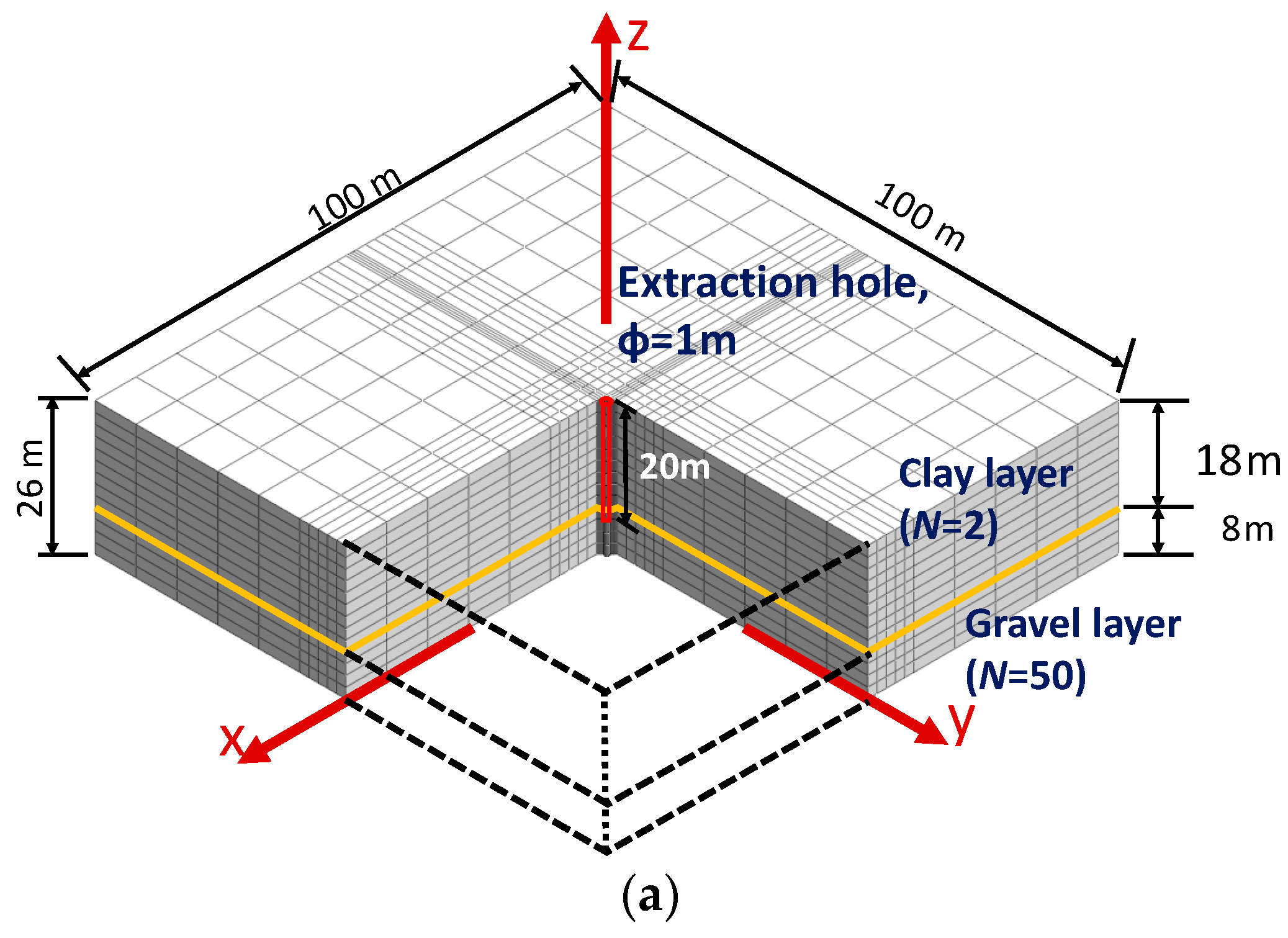
2.2. Cross Section of Target Ground

Around the world, many cities are located on soft ground; thus, there are many structures with pile foundations. In this study, the ground is examined where support piles are in use to support the load through the tip support force working its way upward on the tip of each pile, with the tip of the pile reaching the support layer. In order to show that the soft clay layer is located on a strong gravel layer, an analysis of two sections is carried out. The upper layer, which is soft ground, is a clay layer with an N-value of 2 and a layer thickness of 18 m. The lower layer, which serves as the solid support layer, is a gravel layer with an N-value of about 50 and a layer thickness of 8 m. The N-value is a typical result obtained from a standard penetration test (SPT test). These two sections were selected in order to consider the influence of only the soft ground and the support layer when pulling out the piles. The width of the analysis cross-section is 100 m, the depth is 100 m, and the total cross-section depth is 26 m, so that it is not affected by the boundary conditions. Regarding the arrangement of the extraction holes of removed piles, in order to investigate the mutual influence of the extraction holes of removed piles, the calculation for the existing piles one, two, and three is performed, for which the hole diameter is 1 m, the distance between the extraction holes of the removed piles is 1 m, the depth is 20 m, the ratio of the clay layer:gravel layer:depth of the piles is 9:4:1, and the depth of the penetration into the gravel layer is 2 m. For the mesh division, the accuracy is improved by reducing the mesh spacing near the extraction holes of removed piles. The boundary conditions are a fixed fulcrum on the bottom and a vertical roller fulcrum on the side boundary. The drainage conditions consist of upper and lower drainage boundaries.
In this study, the ground subsidence is compared between the case where there are no holes and the case where there are holes and the holes are hollow. Figure 1 shows the analysis mesh and the analysis cross section. In this figure, the red frame is the part that forms the extraction hole of the removed pile, and the yellow line is the boundary between the clay layer and the gravel layer. Figure 2 shows the process for pulling out the piles. After completely pulling out pile (1), pile (2) and pile (3) are then pulled out 2 m each to form holes.

2.3. Material Parameters of Target Ground

Table 1 shows the parameters of the surrounding ground used for the analysis. The pile foundation parameters are shown in Table 2, and the joint element parameters are shown in Table 3. It is most desirable to use the parameters of the surrounding ground obtained from triaxial compression test results. In this study, however, the parameters were selected from the N-value in order to obtain the generally required strength of the filler. The other parameters are typical values [25,26]. The elastic modulus (E) of the clay layer was calculated by Equation (1), and the elastic modulus (E) of the gravel layer was calculated by Equation (2).
E = 500 N + 6900
E = 2800 N
The internal friction angle ( ϕ ) of the gravel layer was calculated by Equation (3) (the internal friction angle of the clay layer was 0).
ϕ = 20 N + 15
The uniaxial compressive strength (qu) and the adhesive strength (c) of the clay layer were calculated by Equation (4) (the adhesive strength of the gravel layer was 0).
q u = 40 + 2 N c = q u / 2
where γt is the unit volume weight (kN/m3), γsat is the saturation unit volume weight (kN/m3), E is the elastic modulus (kN/m2), ν is Poisson’s ratio (-), c is the adhesive force (kN/m2), ϕ is the internal friction angle (°), qu is the uniaxial compressive strength (kN/m2), k is the hydraulic conductivity (m/s), Kn is the normal stiffness (kN/m3), and Kt is the shear stiffness (kN/m3).
The parameters of the pile foundation were selected with reference to the previous literature [27,28]. For the joint elements of pile foundations, values that are 100 times the small values of the elastic modulus and shear stiffness of the adjacent elements are generally applied [29]. Thus, in this analysis, a value 100 times the shear stiffness of the clay layer was applied to the joint element of the pile foundation.
In addition, the Mohr–Coulomb model [30,31], which is widely used as a failure criterion for clayey soil, was applied to the clay and gravel layers. Although there are certainly more advanced failure criterion models, especially developed for clay and granular materials [32], the Mohr–Coulomb model is known to be the simplest and easiest to use model. When its own weight or external force is applied, shear stress is generated inside the ground, and as this stress increases, the strain increases. With this progression, it slides along a specific surface. Such failure is called the shear failure and the limit value for this is called the shear strength. The soil shear strength ( τ ) represented by this model is shown in Equation (5).
τ = c + tan ϕ
where c is the adhesive force (kN/m2) and ϕ is the internal friction angle (°).

3. Results and Discussion

In this study, in the three-dimensional elasto-plastic consolidation analysis, a comparison is made between the amount of subsidence in the surrounding ground and the compressive stress concentrated in the extraction holes of removed piles when the extraction holes one, two, and three of the removed piles are left hollow.

3.1. Case Where One Extraction Hole of Removed Pile Is Left in a Hollow State

Figure 3 shows the contour diagram for amount of subsidence when one extraction hole of a removed pile is left hollow. Figure 4 presents the amount of subsidence of the ground surface, the clay layer, and the gravel layer during the pile removal process. Figure 5 presents the amount of subsidence of each layer after the pile removal process. The clay layer was Z = 10 m, which was selected because this value shows the maximum subsidence in the clay layer. Figure 6 shows the compressive stress acting on the extraction hole of removed pile.
From Figure 3, it is noted that there is no difference in the location where the maximum amount of subsidence occurs between the time immediately after pulling out the pile and several days after pulling out the pile. In addition, as shown in Figure 4, the amount of subsidence on the ground surface decreases from 8 to 20 m. For this reason, stress is seen to be acting upward as the pile is being pulled out. This is thought to be due to the suction force that acts as the pile is being pulled out. This phenomenon also occurs at the point of 2 m in the gravel layer during the withdrawal.
However, as shown in Figure 5, the amount of subsidence increased with time in the clay layer and the ground surface after the formation of the extraction hole of removed pile. This is thought to be due to the occurrence of depression. By pulling out the pile, a hole is formed and a cavity appears. When this cavity forms, a loosened area is created around the extraction hole of the removed pile. It gradually collapses and the hollow part expands. In addition, the loose area around the extraction hole of removed pile as well as the cavity expands. Sinking is the growth of this cavity reaching the surface, which can occur almost instantaneously. In addition, the subsidence phenomenon caused by mining activities, etc., continues for several months to several years after the completion of these activities [29]. For this reason, it is important to prevent the ground cavity from initially expanding due to the formation of the extraction hole of removed pile.
In addition, the clay layer has more subsidence than the ground surface, even after the hole has been formed. This is because the stress is concentrated in the extraction hole of the removed pile due to the formation of the hole, and the earth pressure increases as the lower clay layer is formed. However, the amount of subsidence does not become maximum near the deepest part of the clay layer. This is thought to be because the lower gravel layer supports the soft clay layer.
From Figure 6, the compressive stress immediately after pulling out the pile can be seen to be almost the same as one week after pulling out the pile. This is thought to be due to the convergence of the consolidation subsidence over time. The compressive stress is small at 18–20 m from the ground surface. This is because this part is a gravel layer, and the vertical displacement over time is considered to be very small compared to the subsidence in the clay layer. In addition, since the amount of subsidence shows the maximum value in the clay layer with Z = 10 m, it is necessary to consider that point as a standard. Moreover, since the age of cement management is generally in units of weeks, it is necessary to pay attention to the strength one week after its injection. Therefore, the filler needs to develop a level of strength of 28 kN/m2 within 7 days. In addition, since a compressive stress of 170 kN/m2 is applied to the periphery of the pile near the bottom of the clay layer before the pile is removed, the filler needs to develop a level of strength of about 170 kN/m2 within 28 days after it is injected into the extraction hole of the removed pile. It is believed that the filler does so.

3.2. Case Where Two Extraction Holes of Removed Piles Are Left in a Hollow State

Figure 7 shows the contour diagram for amount of subsidence when two extraction holes of removed piles are left hollow. Figure 8 presents the amount of subsidence of the ground surface, the clay layer, and gravel layer during the pile removal process. Figure 9 presents the amount of subsidence of each layer after the pile removal process. Furthermore, Figure 10 shows the compressive stress acting on the extraction holes of removed piles.
From Figure 7, it is noted that there is no difference in the location where the maximum amount of subsidence occurs between the time immediately after pulling out the piles and several days after pulling out the piles near the bottom of the clay layer around the extraction hole of the removed pile, as in the case of one extraction hole of a removed pile. However, since pile (2) is pulled out after pile (1) is pulled out, the maximum amount of subsidence occurs in the clay layer sandwiched between pile (2) and the extraction hole of the removed pile (1).
From Figure 8, the amount of subsidence of the ground’s surface decreases from 8 to 20 m due to the pulling-out of piles (1) and (2). This is thought to be due to the fact that a suction force is generated by pulling out the two piles, as in the case of pulling out one pile, and stress is acting upward. In addition, the amount of subsidence immediately after the completion of the extraction of pile (1) is larger than in the case of one extraction hole of a removed pile. This is because pile (2) still exists in the ground immediately after pile (1) is pulled out, but pile (2) is deformed and starts to fall down toward the extraction hole of the removed pile, and the compressive stress concentrated on the extraction hole of removed pile increases. This is very conceivable. In addition, as shown in Figure 9, the amount of subsidence in the surrounding ground is larger than that in the case of one extraction hole of removed pile. As a result, the number of extraction holes of removed piles increases and the depression phenomenon is promoted by an increase in the number of cavities in the ground. Therefore, it is considered necessary to prevent the cavity from expanding earlier when there are two extraction holes of removed piles as compared to the case of one extraction hole of a removed pile. It is important to inject the filler into the extraction hole of a removed pile simultaneously with the formation of the extraction hole of a removed pile [26,27].
Figure 10 shows that the direction of the compressive stress concentrated on the extraction hole of removed pile is greater immediately after pile (2) is withdrawn than immediately after pile (1) is withdrawn. As a result, when the number of extraction holes of removed piles increases, it affects the periphery of the previously formed extraction holes of removed piles, and the compressive stress increases in the lower part of the soft ground. In addition, in the case of one extraction hole of a removed pile, the compressive stress is about 10 kN/m2 on the ground surface, which is smaller than the compressive stress in the extraction hole of the removed pile under the clay layer. However, when there are two extraction holes of removed piles, a compressive stress of approximately 20 kN/m2 acts on the ground surface extraction hole of removed pile immediately after the extraction of pile (2). It acts on the extraction hole of the removed pile at the bottom of the clay layer one week after extraction. The difference in compressive stress is small. Therefore, when multiple extraction holes of removed piles are formed, the compressive stress acting on the ground surface increases and the difference from the compressive stress acting on the extraction hole of removed pile under the clay layer is reduced, so that the strength of the filler is expressed more uniformly. Additionally, as in the case of one extraction hole of removed pile, the compressive stress is reduced from 18 to 20 m from the ground surface, but this part is in the gravel layer, and there is almost no displacement over time from that seen in Figure 8. It is thought that this stress did not cause the subsidence. In addition, since the amount of subsidence shows the maximum value in the clay layer with Z = 10 m, it is necessary to consider that point as a standard. Moreover, since the age of cement management is generally in units of weeks, it is necessary to pay attention to the strength one week after its injection. Therefore, the filler needs to develop a level of strength of 32 kN/m2 within 7 days. In addition, the maximum compressive stress of about 150 kN/m2 is applied to the periphery of the pile before pile removal, which is a small value compared to the case with one extraction hole of removed pile. This is thought to be because the adjacent piles dispersed the stress concentrated on one pile. Therefore, when there are two extraction holes of removed piles, the strength of the filler that should have developed within one week after pulling out the piles must be stronger than that with one extraction hole of a removed pile [33,34].

3.3. Case Where Three Extraction Holes of Removed Piles Are Left in a Hollow State

Figure 11 shows the contour diagram for the amount of subsidence when three extraction holes of removed piles are hollow. Figure 12 presents the amount of subsidence of the ground surface, the clay layer, and the gravel layer during the pile removal process. Figure 13 presents the amount of subsidence of each layer after the pile removal process. Figure 14 shows the compressive stress acting on the extraction hole of removed pile.
As can be seen from Figure 11, as in the case of one or two extraction holes of removed piles, the location where the maximum subsidence occurs immediately after the completion of the extraction and after a certain amount of time has elapsed after the extraction is near the lower part of the clay layer around the extraction hole of removed pile. There is no difference. However, since pile (1) is pulled out first and then pile (2) and pile (3), the maximum subsidence occurs in the clay layer sandwiched between pile (2) and the extraction hole of the removed pile (1).
From Figure 12, the amount of subsidence is seen to decrease on the ground’s surface from 8 to 20 m with the withdrawal of piles (1) and (2). This is thought to be due to the fact that suction force is generated due to the pulling out of the piles and the stress that is acting upward, as in the case of one or two extraction holes of removed piles. In addition, as shown in Figure 13, the amount of subsidence in the surrounding ground is larger than that in the case of one or two extraction holes of removed piles. As a result, it is considered that the phenomenon of depression in the ground increases as the number of extraction holes of removed piles increases. Therefore, in the case of three extraction holes of removed piles, it is necessary to inject the filler simultaneously with the extraction of each pile in order to prevent the cavity from expanding sooner than in the case of one or two extraction holes of removed piles [35,36,37]
Figure 14 shows that the compressive stress concentrated in the extraction hole of a removed pile is greater immediately after pile (2) is extracted than immediately after pile (1) is extracted. However, immediately after pile (3) is extracted, the clay layer expands from 2 to 10 m, and pile (2) is extracted. The compressive stress is smaller than immediately after the removal. If the extraction holes of removed piles do not form in a straight line, the compressive stress acting on the third and subsequent holes will become smaller. In addition, in the case of three extraction holes of removed piles, the compressive stress acting on the ground surface is larger than that in the case of one or two extraction holes of removed piles. As a result, when multiple extraction holes of removed piles are formed, the compressive stress acting on the ground surface increases, and the difference from the compressive stress acting on the extraction hole of removed pile under the clay layer is reduced, so that the strength of the filler is more uniform. In addition, since the amount of subsidence shows the maximum value in the clay layer with Z = 10 m, it is necessary to consider that point as a standard. Moreover, since the age of cement management is generally in units of weeks, it is necessary to pay attention to the strength one week after its injection. Therefore, it is desirable to develop a compressive strength of 32 kN/m2 within one week after pulling out the piles. In addition, the maximum compressive stress of about 140 kN/m2 is applied to the periphery of the pile before the pile removal, which was a small value compared to that in the case of one or two extraction holes of removed piles. This is thought to be because the adjacent piles dispersed the stress concentrated on one pile. Therefore, if there are three extraction holes of removed piles, the strength of the filler that should have developed within one week after pulling out the piles must be stronger than that of one extraction hole of a removed pile. In the case of one, two, or three extraction holes of removed piles, there is not much difference in the compressive stress acting on the extraction hole of removed pile one week after the pile is extracted. As a result, the compressive stress acting on the extraction hole of removed pile converges over time, and the convergence value is thought to be due to the surrounding ground conditions.

4. Conclusions

In this study, a three-dimensional elasto-plastic consolidation analysis was performed to examine the effect of the extraction holes of removed piles on the static properties of the surrounding ground.
The results obtained from the analysis are as follows.
(1)
If an extraction hole of a removed pile is left as it is, large ground subsidence will occur near the extraction hole of the removed pile, especially at the lower part of the clay layer near the hole.
(2)
A cavity grows in the ground around the extraction hole of the removed pile due to the formation of the extraction hole of the removed pile, and the ground subsidence increases with time. In addition, as the number of extraction holes of removed piles increases, the depression phenomenon progresses and countermeasures are required at an early stage. Therefore, it is considered important to inject the filler simultaneously with the formation of each extraction hole of a removed pile.
(3)
In the process of pulling out a pile, the suction force acts on the surrounding ground, so the amount of subsidence on the surrounding ground decreases.
(4)
The greater the number of extraction holes of removed piles, the greater the compressive stress acting on the extraction holes of removed piles after the pile removal. For this reason, the filler should exhibit strength early as the number of extraction holes of removed piles increases.
(5)
When there are two and three extraction holes of removed piles, there is no difference in the compressive stress acting on the extraction holes of removed piles. Therefore, it is thought that the compressive stress acting around each extraction hole of removed pile is caused by the surrounding ground conditions.
(6)
When there is only one extraction hole of a removed pile, there is a difference between the compressive stress concentrated in the extraction hole of a removed pile on the ground’s surface and the compressive stress acting near the lower part of the clay layer. On the other hand, when there are two or three extraction holes of removed piles, the difference in compressive stress acting on the extraction holes of removed piles due to the depth is small. From this, it can be said that as the number of extraction holes of removed piles increases, the necessity to inject a filler that exhibits uniform strength up to the deepest part increases.

Author Contributions

Conceptualization, S.N. and S.I.; methodology, S.I. and A.J.; validation, S.K. and S.C.; formal analysis, S.I.; investigation, S.K., A.J. and S.C.; resources, S.I. and S.K.; data curation, A.J.; writing—original draft preparation, S.I.; writing—review and editing, S.N. and A.J.; visualization, S.I.; supervision, S.N. and S.I.; project administration, S.I. All authors have read and agreed to the published version of the manuscript.

Funding

This research received no external funding.

Institutional Review Board Statement

Not applicable.

Informed Consent Statement

Not applicable.

Data Availability Statement

Not applicable.

Conflicts of Interest

The authors declare no conflict of interest.

References

  1. Yoshioka, S.; Kawasaki, H. Japan’s High-Growth Postwar Period (The Role of Economic Plans); ESRI Research Note 2016; Cabinet Office: Tokyo, Japan, 2016; Volume 27, pp. 1–82. [Google Scholar]
  2. Ministry of Land, Infrastructure, Transport and Tourism (MLIT). Public Building Construction Standard Specification (Building Work), 2013th ed.; Ministry of Land, Infrastructure, Transport and Tourism: Tokyo, Japan, 2016. [Google Scholar]
  3. Inazumi, S.; Tanaka, S.; Komaki, T.; Kuwahara, S. Effect of insertion of casing by rotation on existing piles in removal of existing pile. Geotech. Res. 2021, 8, 25–37. [Google Scholar] [CrossRef]
  4. Takao, M. Leaving the foundation pile, backfilling denied the defects of ground support force of the part, agent of accountability violation was also negative case. RETIO 2011, 82, 166–167. [Google Scholar]
  5. Kuwahara, S.; Inazumi, S.; Jotisankasa, A.; Chaiprakaikeow, S. Influence of the condition of pullout holes on the surrounding ground. Int. J. Geo-Eng. 2020, 11, 10. [Google Scholar] [CrossRef]
  6. Inazumi, S.; Kuwahara, S.; Jotisankasa, A.; Chaiprakaikeow, S. Construction method for pulling out existing piles and influence of pulling-out holes on the surrounding ground. Geotech. Geol. Eng. 2020, 38, 6107–6123. [Google Scholar] [CrossRef]
  7. Kuwahara, S.; Inazumi, S. Settlement of surrounding grounds due to existence of pile pulling-out holes. Int. J. Geomate Geotech. Constr. Mater. Environ. 2019, 16, 81–85. [Google Scholar] [CrossRef]
  8. Inazumi, S.; Kuwahara, S.; Jotisankasa, A.; Chaiprakaikeow, S. MPS-CAE simulation on dynamic interaction between steel casing and existing pile when pulling out existing piles. Int. J. Geomate: Geotech. Constr. Mater. Environ. 2020, 18, 68–73. [Google Scholar] [CrossRef]
  9. Nakao, K.; Inazumi, S.; Takaue, T.; Tanaka, S.; Shinoi, T. Evaluation of Discharging Surplus Soils for Relative Stirred Deep Mixing Methods by MPS-CAE Analysis. Sustainability 2022, 14, 58. [Google Scholar] [CrossRef]
  10. Inazumi, S.; Kuwahara, S.; Jotisankasa, A.; Chaiprakaikeow, S. Improvement mechanism of sodium carbonate on traditional composite filler. Ground Improv. 2021, 174, 132–139. [Google Scholar] [CrossRef]
  11. Hang, C.; Gao, X.; Yuan, M.; Huang, Y.; Zhu, R. Discrete element simulations and experiments of soil disturbance as affected by the tine spacing of subsoiler. Biosyst. Engineering. 2018, 168, 73–82. [Google Scholar] [CrossRef]
  12. Cundall, P.A.; Hart, R.D. Numerical modeling of discontinua. Anal. Des. Methods 1993, 231–243. [Google Scholar] [CrossRef]
  13. Antoniou, A.; Daudeville, L.; Marin, P.; Omar, A.; Potapov, S. Discrete element modelling of concrete structures under hard impact by ogive-nose steel projectiles. Eur. Phys. J. Spec. Top. 2018, 227, 143–154. [Google Scholar] [CrossRef]
  14. Inazumi, S.; Hamaguchi, S.; Kuwahara, S. Performance evaluation of backfilling methods by improved air-lift on pulling-out holes of existing piles. J. Jpn. Constr. Mach. Constr. Assoc. 2018, 70, 91–101. [Google Scholar]
  15. Inazumi, S.; Shakya, S.; Komaki, T.; Nakanishi, Y. Numerical analysis on performance of middle-pressure jet grouting method for ground improvement. Geosciences 2021, 11, 313. [Google Scholar] [CrossRef]
  16. Inazumi, S.; Hashimoto, R.; Shinsaka, T.; Nontananandh, S.; Chaiprakaikeow, S. Applicability of Additives for Ground Improvement Utilizing Fine Powder of Waste Glass. Materials 2021, 14, 5169. [Google Scholar] [CrossRef]
  17. Inazumi, S.; Shishido, K.; Soralump, S. Possibility of impervious coating for the geotechnical reuse of soil and solid waste. Environ. Geotech. 2021, 8, 324–333. [Google Scholar] [CrossRef]
  18. Kumar, N.; Dey, A. Finite element analysis of flexible anchored sheet pile walls: Effect of mode of construction and dewatering. In Proceeding of Golden Jubilee Conference of the IGS Bangalore Chapter, Geo-Innovations, Bangalore, India, 30–31 October 2014; pp. 1–8. [Google Scholar]
  19. Mroueh, H.; Shahrour, I. Numerical analysis of the response of battered piles to inclined pullout loads. Int. J. Numer. Anal. Meth. Geomech. 2018, 33, 1277–1288. [Google Scholar] [CrossRef]
  20. Zheng, G.; Yang, X.; Zhou, H.; Du, Y.; Sun, J.; Yu, X. A simplified prediction method for evaluating tunnel displacement induced by laterally adjacent excavations. Comput. Geotech. 2018, 95, 119–128. [Google Scholar] [CrossRef]
  21. Small, J.C.; Booker, J.R.; Davis, E.H. Elasto-plastic consolidation of soil. Int. J. Solids Struct. 1976, 12, 431–448. [Google Scholar] [CrossRef]
  22. Saini, S.; Goyal, E.T. Analysis of piled raft foundation using MIDAS GTS NX. Int. Res. J. Eng. Technol. 2019, 6, 5491–5499. [Google Scholar]
  23. Cao, Q.; Hang, Y. Settlement simulation of soft clay in the subway under dynamic load based on Midas GTS NX. E3S Web Conf. 2021, 237, 03011. [Google Scholar] [CrossRef]
  24. Wang, Z. Comparative analysis of Midas GTS NX and SLOPE/W numerical simulation softwares. Int. Core J. Eng. 2020, 6, 83–85. [Google Scholar] [CrossRef]
  25. Bałachowski, L. Physical modelling of geotechnical structures in ports and offshore. Pol. Marit. Res. 2017, 24, 4–9. [Google Scholar] [CrossRef] [Green Version]
  26. Nakazawa, F.; Furugaichi, Y. Evaluation of Young’s modulus of liquidity stabilized soil. Tokyu Constr. Tech. Rep. 2015, 40, 49–52. [Google Scholar]
  27. Furugaichi, Y. Deformation properties of the backfill material which has a fluidity and self-hardening. Town Value-Up Manag. Rep. 2011, 37, 41–44. [Google Scholar]
  28. Li, S.Z.; Ren, F.; Sheng, G.L.; Zhao, W.P. Three-dimensional numerical analysis of deformation of various combined support forms. IOP Conf. Ser. Mater. Sci. Eng. 2018, 423, 012025. [Google Scholar] [CrossRef]
  29. Ambrosini, D.; Luccioni, B. Effects of underground explosions on soil and structures. Undergr. Space 2020, 5, 324–338. [Google Scholar] [CrossRef]
  30. Cho, H.; Bang, E.S.; Yi, M.J.; Kim, D.S. Physical modeling of ground subsidence due to underground cavity and its monitoring by electrical resistivity survey in geotechnical centrifuge. In Proceedings of the 15th Asian Regional Conference on Soil Mechanics and Geotechnical Engineering, Kyushu, Japan, 9–13 November 2014. [Google Scholar] [CrossRef] [Green Version]
  31. Heib, M.A.; Emeriault, F.; Ngjiem, H.L. On the use of 1g physical models for ground movements and soil-structure interaction problems. J. Rock Mech. Geotech. Eng. 2020, 12, 197–211. [Google Scholar] [CrossRef]
  32. Goldstein, R.V.; Dudchenko, A.V.; Kuznetsov, S.V. The modified Cam-Clay (MCC) model: Cyclic kinematic deviatoric loading. Arch. Appl. Mech. 2016, 86, 2021–2031. [Google Scholar] [CrossRef]
  33. Akishige, H.; Tamura, M.; Watanabe, K.; Kimura, T.; Nemoto, H.; Kaneko, O.; Mizutani, Y.; Abe, A. Performance evaluation method of foundation in building regulations of Japan and oversea (Part 1: Limitations of settlement). In Proceedings of the Summaries of Technical Papers of Annual Meeting, Stockholm, Switzerland, 12–16 January 2004; pp. 621–622. [Google Scholar]
  34. Aydin, A.; Johnson, A. Development of faults as zones of deformation bands and as slip surfaces in sandstone. Pure Appl. Geophys. 1978, 116, 931–942. [Google Scholar] [CrossRef]
  35. Resare, F. Analysis of an Inclined Pile in Settling Soil. Master’s Thesis, Royal Institute of Technology, Stockholm, Switzerland, 2015; pp. 1–34. [Google Scholar]
  36. Inazumi, S.; Intui, S.; Jotisankasa, A.; Chaiprakaikeow, S.; Shinsaka, T. Applicability of mixed solidification material based on inorganic waste as soil stabilizer. Case Stud. Constr. Mater. 2020, 12, e00305. [Google Scholar] [CrossRef]
  37. Nakao, K.; Inazumi, S.; Takaue, T.; Tanaka, S.; Shinoi, T. Visual evaluation of relative deep mixing method type of ground-improvement method. Results Eng. 2021, 10, 100233. [Google Scholar] [CrossRef]
Figure 1. Analysis of cross-section on ground with extraction holes of removed piles; (a) case with one extraction hole of removed pile; (b) case with two extraction holes of removed piles; (c) case with three extraction holes of removed piles.
Applsci 12 05481 g001aApplsci 12 05481 g001b
Figure 2. Process of pulling out existing piles.
Applsci 12 05481 g002
Figure 3. Deformation of the surrounding ground when one extraction hole of a removed pile is hollow.
Applsci 12 05481 g003
Figure 4. Subsidence of the surrounding ground during the process of forming one extraction hole of a removed pile.
Applsci 12 05481 g004
Figure 5. Subsidence of the surrounding ground after forming one extraction hole of a removed pile.
Applsci 12 05481 g005
Figure 6. Compressive stress concentrated on one extraction hole of a removed pile.
Applsci 12 05481 g006
Figure 7. Deformation of surrounding ground when two extraction holes of removed piles are hollow.
Applsci 12 05481 g007
Figure 8. Amount of subsidence of the surrounding ground in the process of forming two extraction holes of removed piles.
Applsci 12 05481 g008
Figure 9. Subsidence of the surrounding ground after the formation of two extraction holes of removed piles.
Applsci 12 05481 g009
Figure 10. Compressive stress concentrated on two extraction holes of removed piles.
Applsci 12 05481 g010
Figure 11. Deformation of the surrounding ground when three extraction holes of removed piles are hollow.
Applsci 12 05481 g011
Figure 12. Subsidence of the surrounding ground in the process of forming three extraction holes of removed piles.
Applsci 12 05481 g012
Figure 13. Subsidence of the surrounding ground after the formation of three extraction holes of removed piles.
Applsci 12 05481 g013
Figure 14. Compressive stress concentrated on three extraction holes of removed piles.
Applsci 12 05481 g014
Table 1. Parameters of the surrounding ground used for the analysis.
Clay LayerGravel Layer
γt(kN/m3)1521
γsat(kN/m3)1621
E(kN/m3)7.9 × 1031.4 × 105
ν(-)0.450.3
c(kN/m2)25.00
φ(°)047
N-value(-)250
qu(kN/m2)502.5 × 103
k(m/s)1.0 × 10−81.0 × 10−5
Table 2. Parameters of the pile foundation used for the analysis.
γt (kN/m3)E (kN/m2)ν (-)
Pile foundation242.1 × 1070.18
Table 3. Parameters of the joint element used for the analysis.
Kn (kN/m3)Kt (kN/m3)
Joint element3.0 × 1043.0 × 105
Publisher’s Note: MDPI stays neutral with regard to jurisdictional claims in published maps and institutional affiliations.

