
Numerical Simulation of Deformation and Failure Mechanism of Main Inclined Shaft in Yuxi Coal Mine, China


Abstract
:1. Introduction
2. Engineering Overview and Research Background
2.1. Geographical Location
2.2. Engineering Geological Characteristics
2.3. Research Background
3. Numerical Model
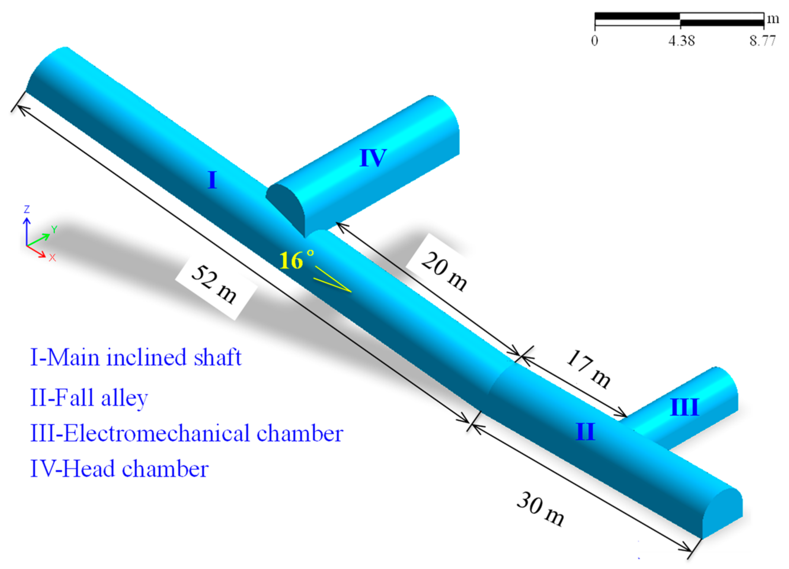
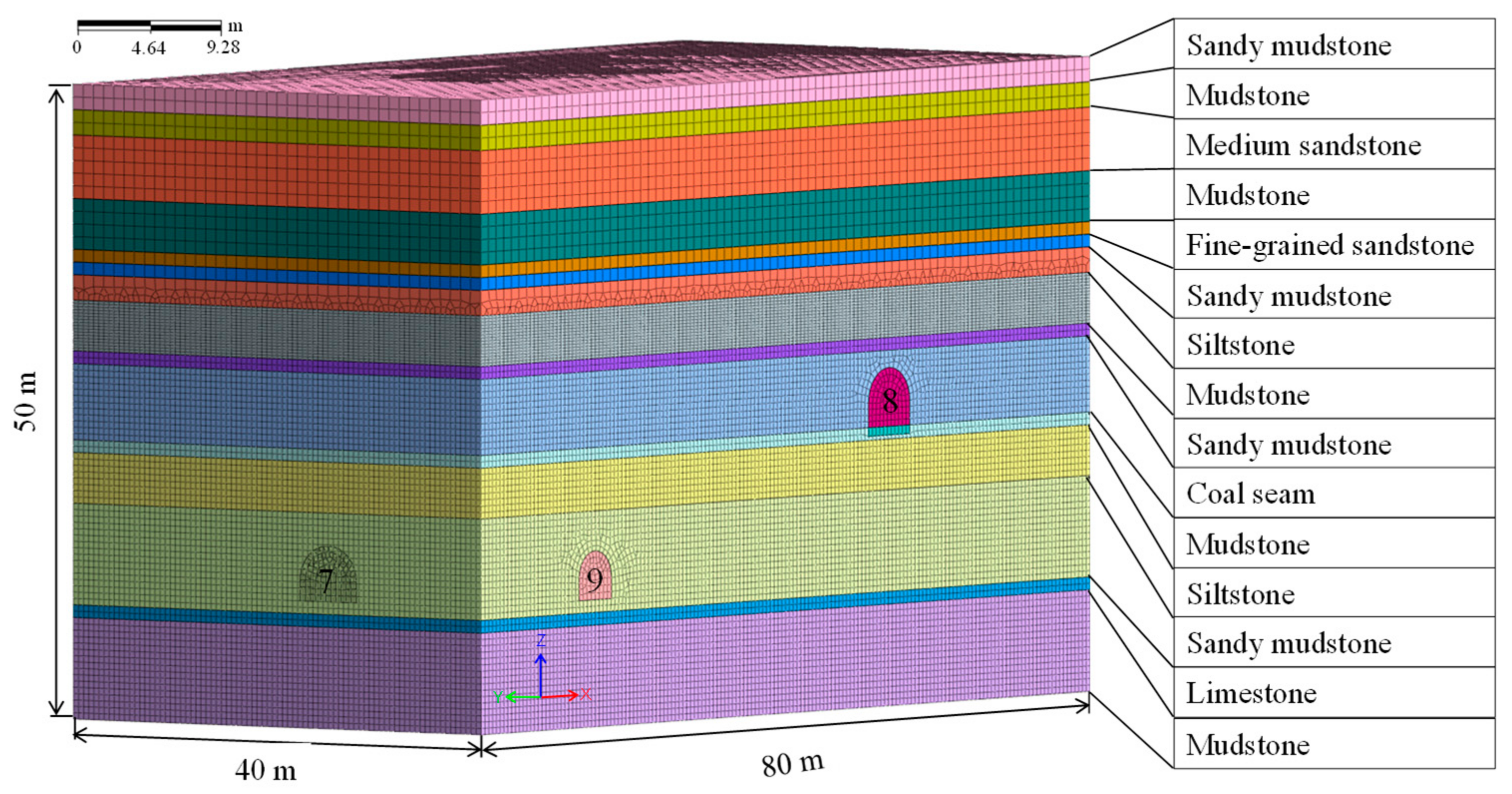
3.1. Physical Model
3.2. Determination of Model Parameters
3.3. Model Analysis and Design
4. Results
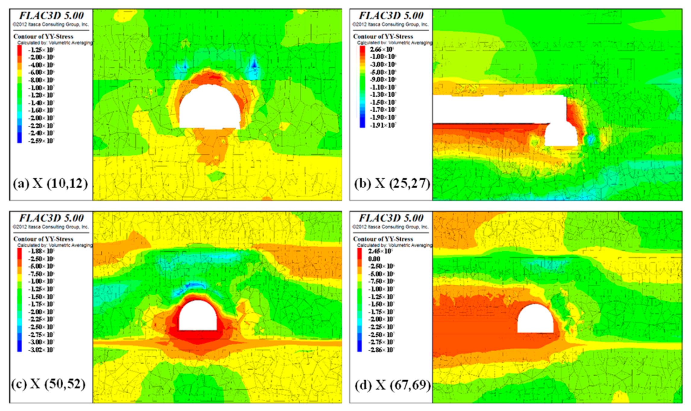
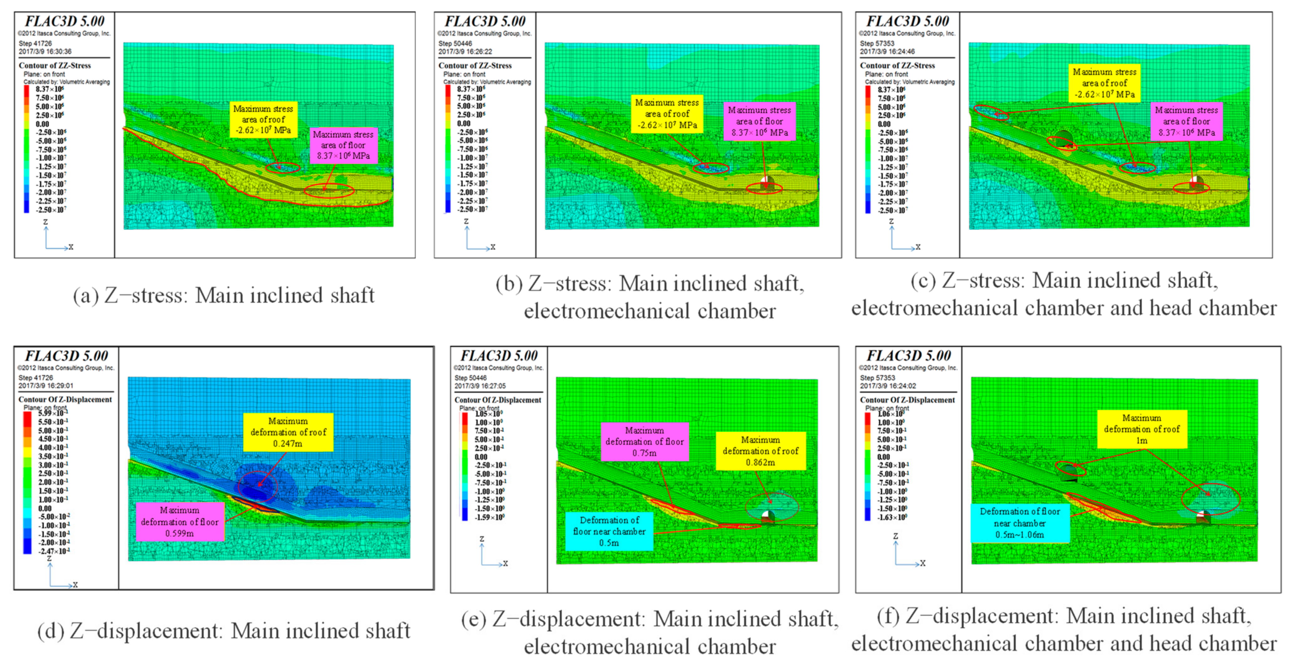
4.1. Effect of Stress Disturbance
4.1.1. Surrounding Rock Stress of Main Inclined Shaft without Excavation Disturbance
4.1.2. Surrounding Rock Stress of Main Inclined Shaft after Excavation of Electromechanical Chamber
4.1.3. Surrounding Rock Stress of Main Inclined Shaft after Excavation of Head Chamber in Belt Roadway
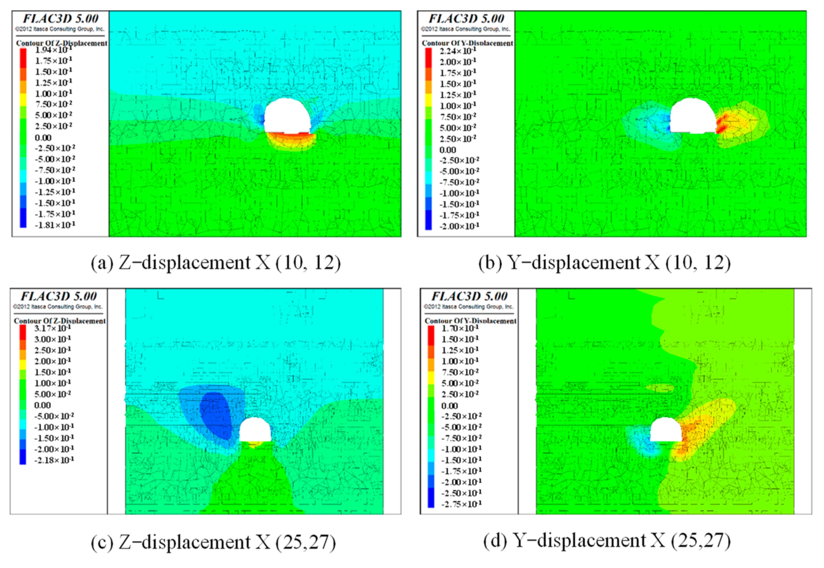
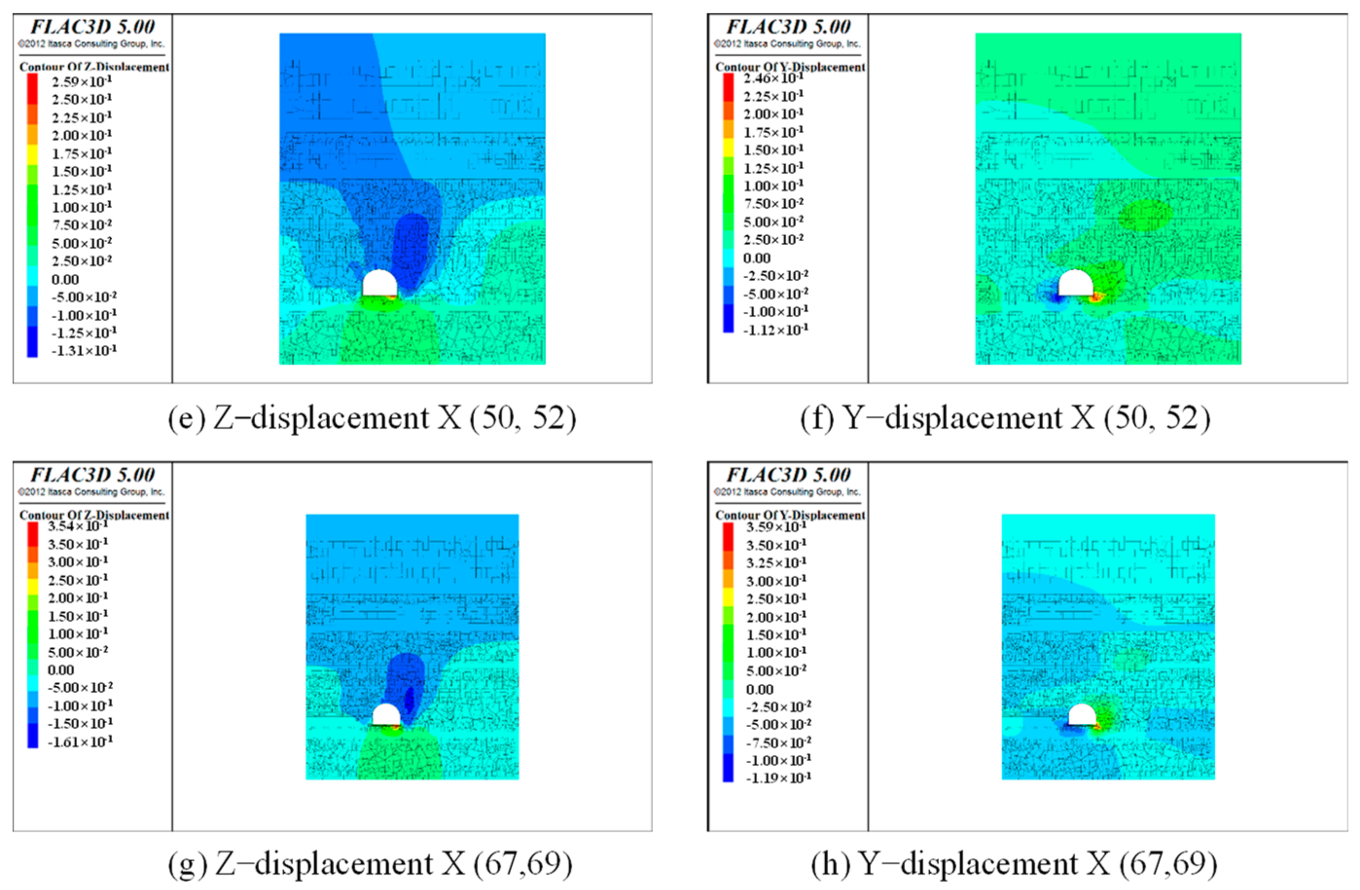
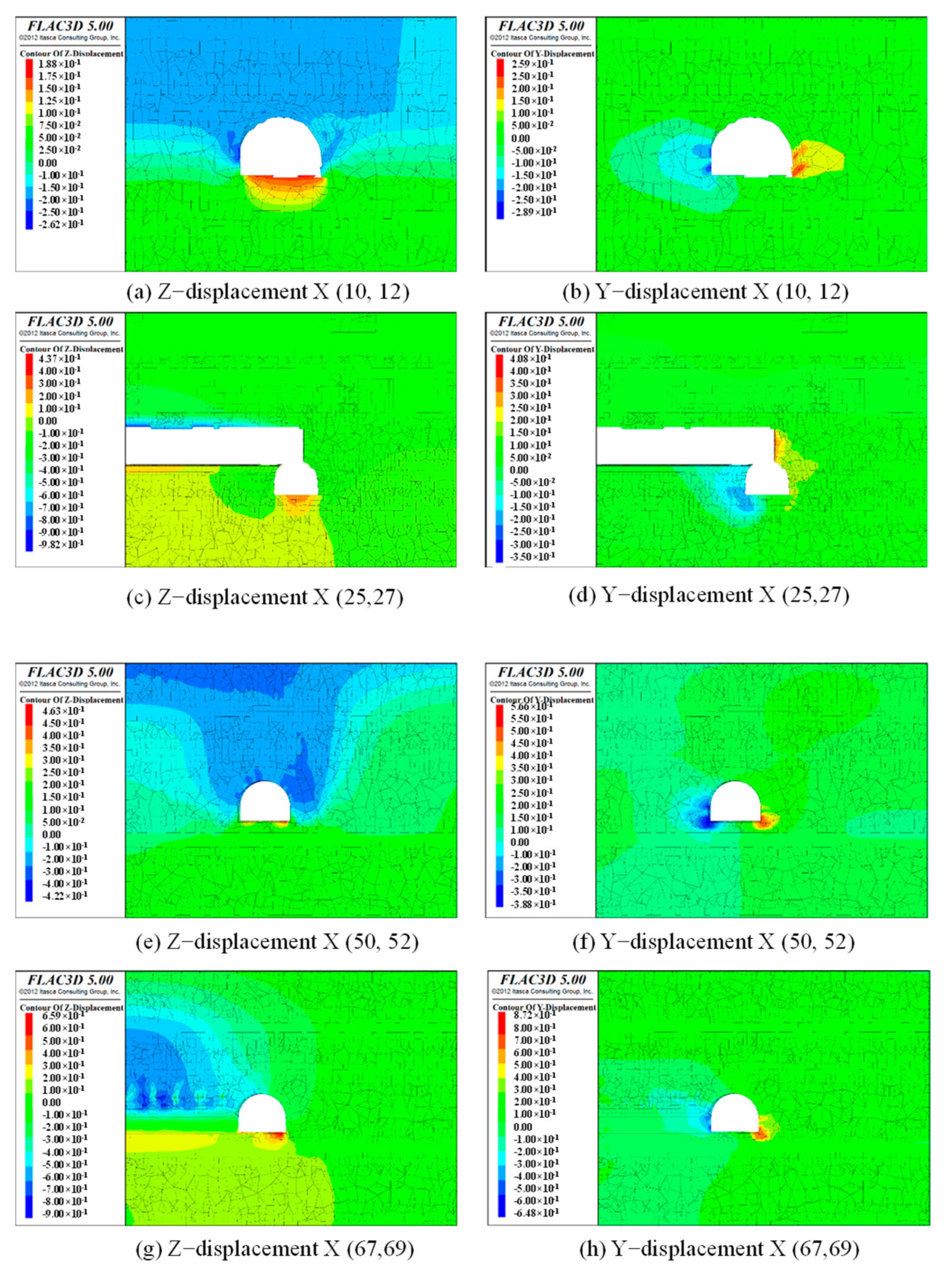
4.2. Displacement Evolution Analysis
4.2.1. Surrounding Rock Displacement of Main Inclined Shaft without Excavation Disturbance
4.2.2. Surrounding Rock Displacement of Main Inclined Shaft after Excavation of Electromechanical Chamber
4.2.3. Surrounding Rock Displacement of Main Inclined Shaft after Excavation of Head Chamber of Belt Roadway
4.3. Analysis of Disturbance Influence Profile
5. Discussion
6. Conclusions
Author Contributions
Funding
Institutional Review Board Statement
Informed Consent Statement
Data Availability Statement
Conflicts of Interest
References
- Xie, H.; Ju, Y.; Ren, S.; Gao, F.; Liu, J.; Zhu, Y. Theoretical and Technological Exploration of Deep in Situ Fluidized Coal Mining. Front. Energy 2019, 13, 603–611. [Google Scholar] [CrossRef]
- Wang, C.; Xiong, Z.; Wang, C.; Wang, Y.; Zhang, Y. Study on Rib Sloughage Prevention Based on Geological Structure Exploration and Deep Borehole Grouting in Front Abutment Zones. Geofluids 2020, 2020, 7961032. [Google Scholar] [CrossRef]
- Qin, D.; Wang, X.; Zhang, D.; Chen, X. Study on Surrounding Rock-Bearing Structure and Associated Control Mechanism of Deep Soft Rock Roadway under Dynamic Pressure. Sustainability 2019, 11, 1892. [Google Scholar] [CrossRef] [Green Version]
- Zhang, J.; Wang, Y.; Yao, B.; Chen, D.; Sun, C.; Jia, B. Investigation of Deep Shaft-Surrounding Rock Support Technology Based on a Post-Peak Strain-Softening Model of Rock Mass. Appl. Sci. 2022, 12, 253. [Google Scholar] [CrossRef]
- Xie, H.; Gao, F.; Ju, Y. Research and Development of Rock Mechanics in Deep Ground Engineering. Chin. J. Rock Mech. Eng. 2015, 34, 2161–2178. [Google Scholar] [CrossRef]
- Srivastava, L.P.; Singh, M. Empirical Estimation of Strength of Jointed Rocks Traversed by Rock Bolts Based on Experimental Observation. Eng. Geol. 2015, 197, 103–111. [Google Scholar] [CrossRef]
- Shi, X.; Jing, H.; Zhao, Z.; Gao, Y.; Zhang, Y.; Bu, R. Physical Experiment and Numerical Modeling on the Failure Mechanism of Gob-Side Entry Driven in Thick Coal Seam. Energies 2020, 13, 5425. [Google Scholar] [CrossRef]
- Du, J.; Chen, J.; Pu, Y.; Jiang, D.; Chen, L.; Zhang, Y. Risk Assessment of Dynamic Disasters in Deep Coal Mines Based on Multi-Source, Multi-Parameter Indexes, and Engineering Application. Process Saf. Environ. Prot. 2021, 155, 575–586. [Google Scholar] [CrossRef]
- Wang, E.; Chen, G.; Yang, X.; Zhang, G.; Guo, W. Study on the Failure Mechanism for Coal Roadway Stability in Jointed Rock Mass Due to the Excavation Unloading Effect. Energies 2020, 13, 2515. [Google Scholar] [CrossRef]
- Yu, X. On the Theory of Axial Variation and Basic Rules of Deformation and Fracture of Rocks Surrounding Underground Excavations. Uranium Min. Metall. 1982, 1, 8–17. [Google Scholar]
- Song, Z.; Wei, W.; Tan, J. Effect of Combined Mining with Steeply Dipping Seam on Stability of Surrounding Rock of Inclined Shaft in Weakly Cemented Stratum. IOP Conf. Ser. Earth Environ. Sci. 2019, 237, 032108. [Google Scholar] [CrossRef]
- Islam, M.R.; Hayashi, D.; Kamruzzaman, A.B.M. Finite Element Modeling of Stress Distributions and Problems for Multi-Slice Longwall Mining in Bangladesh, with Special Reference to the Barapukuria Coal Mine. Int. J. Coal Geol. 2009, 78, 91–109. [Google Scholar] [CrossRef]
- Yao, Z.; Song, H.; Cheng, H.; Rong, C. The Experimental Study on Inner Shift Lining Structure of Freezing Shaft in Deep Thick Aquiferous Soft Rock. AGH J. Min. Geoengin. 2012, 36, 463–470. [Google Scholar]
- Cao, S.; Luo, F.; Cheng, C.; Li, G.; Guo, P. Surrounding Rock Control of Shaft in Water Enriched Fault Fracture Zone. Chin. J. Rock Mech. Eng. 2014, 33, 1536–1545. [Google Scholar] [CrossRef]
- Ma, L.; Jin, Z.; Liang, J.; Sun, H.; Zhang, D.; Li, P. Simulation of Water Resource Loss in Short-Distance Coal Seams Disturbed by Repeated Mining. Environ. Earth Sci. 2015, 74, 5653–5662. [Google Scholar] [CrossRef]
- Yang, X.; Kulatilake, P.H.S.W.; Jing, H.; Yang, S. Numerical Simulation of a Jointed Rock Block Mechanical Behavior Adjacent to an Underground Excavation and Comparison with Physical Model Test Results. Tunn. Undergr. Space Technol. 2015, 50, 129–142. [Google Scholar] [CrossRef]
- Gao, F.; Stead, D.; Coggan, J. Evaluation of Coal Longwall Caving Characteristics Using an Innovative UDEC Trigon Approach. Comput. Geotech. 2014, 55, 448–460. [Google Scholar] [CrossRef] [Green Version]
- Yang, S.; Chen, M.; Jing, H.; Chen, K.; Meng, B. A Case Study on Large Deformation Failure Mechanism of Deep Soft Rock Roadway in Xin’An Coal Mine, China. Eng. Geol. 2017, 217, 89–101. [Google Scholar] [CrossRef]
- Mudunuru, M.K.; Nakshatrala, K.B. On Enforcing Maximum Principles and Achieving Element-Wise Species Balance for Advection–Diffusion–Reaction Equations under the Finite Element Method. J. Comput. Phys. 2015, 305, 448–493. [Google Scholar] [CrossRef] [Green Version]
- Xing, Y.; Kulatilake, P.H.S.W.; Sandbak, L.A. Effect of Rock Mass and Discontinuity Mechanical Properties and Delayed Rock Supporting on Tunnel Stability in an Underground Mine. Eng. Geol. 2018, 238, 62–75. [Google Scholar] [CrossRef]
- Wang, X.; Tian, L. Mechanical and Crack Evolution Characteristics of Coal–Rock under Different Fracture-Hole Conditions: A Numerical Study Based on Particle Flow Code. Environ. Earth Sci. 2018, 77, 297. [Google Scholar] [CrossRef]
- Li, G.; Ma, F.; Guo, J.; Zhao, H. Case Study of Roadway Deformation Failure Mechanisms: Field Investigation and Numerical Simulation. Energies 2021, 14, 1032. [Google Scholar] [CrossRef]
- Hou, D.; Yang, X. Physical Modeling of Displacement and Failure Monitoring of Underground Roadway in Horizontal Strata. Adv. Civ. Eng. 2018, 2018, 2934302. [Google Scholar] [CrossRef] [Green Version]
- Chen, X.; Wang, J.G. Stability Analysis for Compressed Air Energy Storage Cavern with Initial Excavation Damage Zone in an Abandoned Mining Tunnel. J. Energy Storage 2022, 45, 103725. [Google Scholar] [CrossRef]
- Zha, E.; Zhang, Z.; Zhang, R.; Wu, S.; Li, C.; Ren, L.; Gao, M.; Zhou, J. Long-Term Mechanical and Acoustic Emission Characteristics of Creep in Deeply Buried Jinping Marble Considering Excavation Disturbance. Int. J. Rock Mech. Min. Sci. 2021, 139, 104603. [Google Scholar] [CrossRef]
- Wang, H.; Cheng, Y.; Yuan, L. Gas Outburst Disasters and the Mining Technology of Key Protective Seam in Coal Seam Group in the Huainan Coalfield. Nat. Hazards 2013, 67, 763–782. [Google Scholar] [CrossRef]
- Chen, S.; Wu, A.; Wang, Y.; Chen, X.; Yan, R.; Ma, H. Study on Repair Control Technology of Soft Surrounding Rock Roadway and Its Application. Eng. Fail. Anal. 2018, 92, 443–455. [Google Scholar] [CrossRef]
- He, M.C.; Li, C.H.; Wang, S.R. Research on the Non-Linear Mechanics Characters of Large Section Cavern Excavating within Soft Rock by Numerical Simulation. Chin. J. Geotech. Eng. 2002, 4, 483–486. [Google Scholar]
- Sun, H.; Gao, E.; Zhou, A. Numerical Simulation of Uneven Settlement of Municipal Solid Waste Landfill by FLAC 3D. Waste Manag. Res. 2022, 40, 374–382. [Google Scholar] [CrossRef]
- Schumacher, F.P.; Kim, E. Evaluation of Directional Drilling Implication of Double Layered Pipe Umbrella System for the Coal Mine Roof Support with Composite Material and Beam Element Methods Using FLAC 3D. J. Min. Sci. 2014, 50, 335–348. [Google Scholar] [CrossRef]
- Wu, Y.; Yang, Y.; Lai, X.; Xie, P. Numerical Simulation and Determination of Bolt Parameters of Roadways. J. Min. Saf. Eng. 2006, 23, 398–401. [Google Scholar]
- Gao, F.Q.; Kang, H.P.; Lin, J. Numerical Simulation of Zonal Distrigation of Surrounding Rock Mass in Deep Mine Roadways. J. China Coal Soc. 2010, 35, 21–25. [Google Scholar]
- Wu, F.; Chen, Z.; Cui, Q. Disturbance and Damage Effect of Underground Chamber Excavation on Main Inclined Shaft in Yuxi Coal Mine. China Energy Environ. Prot. 2019, 41, 148–153. [Google Scholar]


| Strat Graphic Number | Horizon | Lithology | Layer Thickness (m) | Volume Modulus (GPa) | Shear Modulus (GPa) | Tensile Strength (MPa) | Cohesion (MPa) | Internal Friction Angle (°) | Bulk Density (KN·m−3) |
|---|---|---|---|---|---|---|---|---|---|
| GS-No. 01 | Overlying strata | Sandy mudstone | 2.00 | 2.81 | 1.03 | 1.41 | 0.722 | 25.4 | 26.1 |
| GS-No. 02 | Overlying strata | Mudstone | 2.15 | 2.81 | 1.03 | 1.41 | 0.722 | 25.4 | 26.1 |
| GS-No. 03 | Overlying strata | Medium sandstone | 5.50 | 4.07 | 2.58 | 1.82 | 1.410 | 27.4 | 27.9 |
| GS-No. 04 | Overlying strata | Mudstone | 3.85 | 2.81 | 1.03 | 1.41 | 0.722 | 25.4 | 26.1 |
| GS-No. 05 | Overlying strata | Fine-grained sandstone | 1.30 | 3.87 | 2.13 | 1.64 | 1.260 | 26.3 | 26.5 |
| GS-No. 06 | Overlying strata | Sandy mudstone | 1.45 | 2.81 | 1.03 | 1.41 | 0.722 | 25.4 | 26.1 |
| GS-No. 07 | Overlying strata | Siltstone | 1.90 | 2.82 | 1.05 | 1.43 | 0.736 | 26.4 | 27.3 |
| GS-No. 08 | Main inclined shaft | Mudstone | 3.55 | 2.81 | 1.03 | 1.41 | 0.722 | 25.4 | 26.1 |
| GS-No. 09 | Main inclined shaft | Sandy mudstone | 1.12 | 2.81 | 1.03 | 1.41 | 0.722 | 25.4 | 26.1 |
| GS-No. 10 | Main inclined shaft | Coal seam | 5.85 | 5.20 | 0.38 | 0.64 | 2.030 | 26.0 | 13.0 |
| Belt alley | Coal seam | 5.85 | 5.20 | 0.38 | 0.64 | 2.030 | 26.0 | 13.0 | |
| GS-No. 11 | Main inclined shaft | Mudstone | 0.57 | 2.81 | 1.03 | 1.41 | 0.722 | 25.4 | 26.1 |
| Belt alley | Mudstone | 0.57 | 2.81 | 1.03 | 1.41 | 0.722 | 25.4 | 26.1 | |
| GS-No. 12 | Main inclined shaft | Siltstone | 4.51 | 2.82 | 1.05 | 1.43 | 0.736 | 26.4 | 27.3 |
| GS-No. 13 | Main inclined shaft | Sandy mudstone | 7.75 | 2.81 | 1.03 | 1.41 | 0.722 | 25.4 | 26.1 |
| GS-No. 14 | Underlying strata | Limestone | 0.80 | 2.30 | 1.94 | 2.60 | 3.350 | 38.7 | 27.4 |
| GS-No. 15 | Underlying strata | Mudstone | 7.70 | 2.81 | 1.03 | 1.41 | 0.722 | 25.4 | 26.1 |
| Name | Length (mm) | Exposure (mm) | Spacing (mm) | Line Spacing (mm) | Cross Sectional Area (mm2) | Cohesion (GPa) | Anchoring Force (GPa) | Elastic Modulus (GPa) | Tensile Strength (MPa) |
|---|---|---|---|---|---|---|---|---|---|
| Anchor cable | 7300 | 300 | 1200 | 2400 | 1 | 10 | 40 | 20 | 1.3 |
| Bolt | 2400 | 300 | 1200 | 1000 | 1 | 10 | 2 | 20 | 10 |
Publisher’s Note: MDPI stays neutral with regard to jurisdictional claims in published maps and institutional affiliations. |
© 2022 by the authors. Licensee MDPI, Basel, Switzerland. This article is an open access article distributed under the terms and conditions of the Creative Commons Attribution (CC BY) license (https://creativecommons.org/licenses/by/4.0/).
Share and Cite
Wu, F.; Qin, Y.; Xu, H.; Zhang, F.; Chu, X. Numerical Simulation of Deformation and Failure Mechanism of Main Inclined Shaft in Yuxi Coal Mine, China. Appl. Sci. 2022, 12, 5531. https://doi.org/10.3390/app12115531
Wu F, Qin Y, Xu H, Zhang F, Chu X. Numerical Simulation of Deformation and Failure Mechanism of Main Inclined Shaft in Yuxi Coal Mine, China. Applied Sciences. 2022; 12(11):5531. https://doi.org/10.3390/app12115531
Chicago/Turabian StyleWu, Fan, Yueping Qin, Hao Xu, Fengjie Zhang, and Xiangyu Chu. 2022. "Numerical Simulation of Deformation and Failure Mechanism of Main Inclined Shaft in Yuxi Coal Mine, China" Applied Sciences 12, no. 11: 5531. https://doi.org/10.3390/app12115531