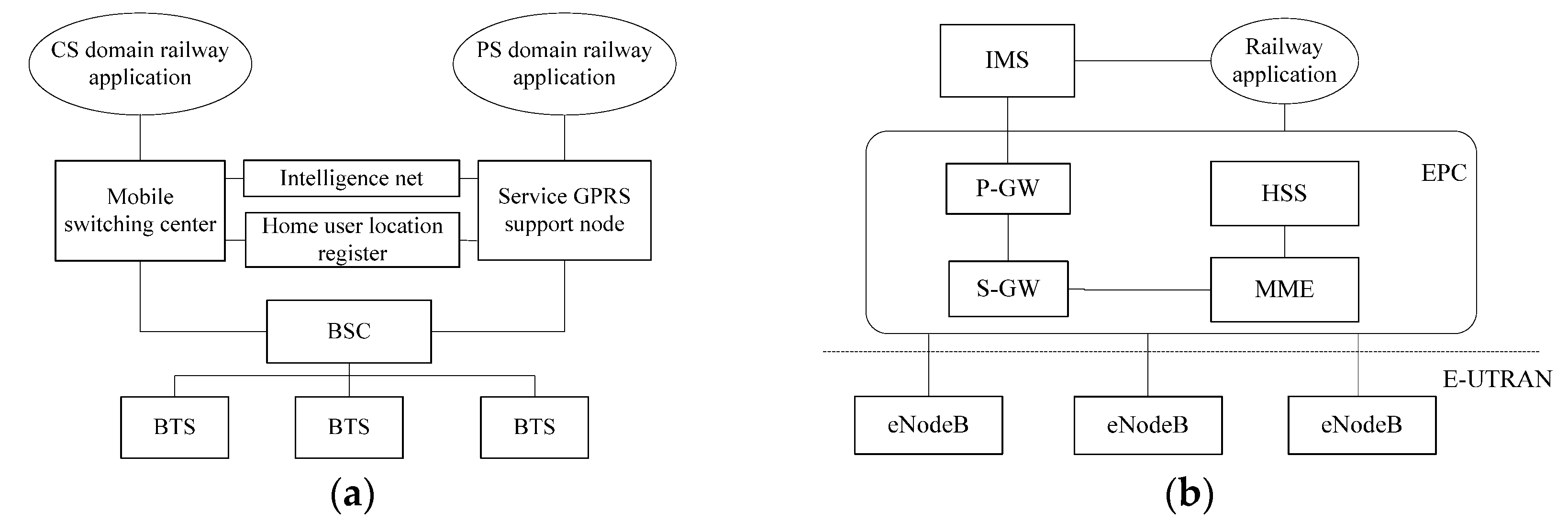
4.2. Modeling Analysis of LTE-R Time Synchronization Vulnerability Based on Stochastic Petri Nets
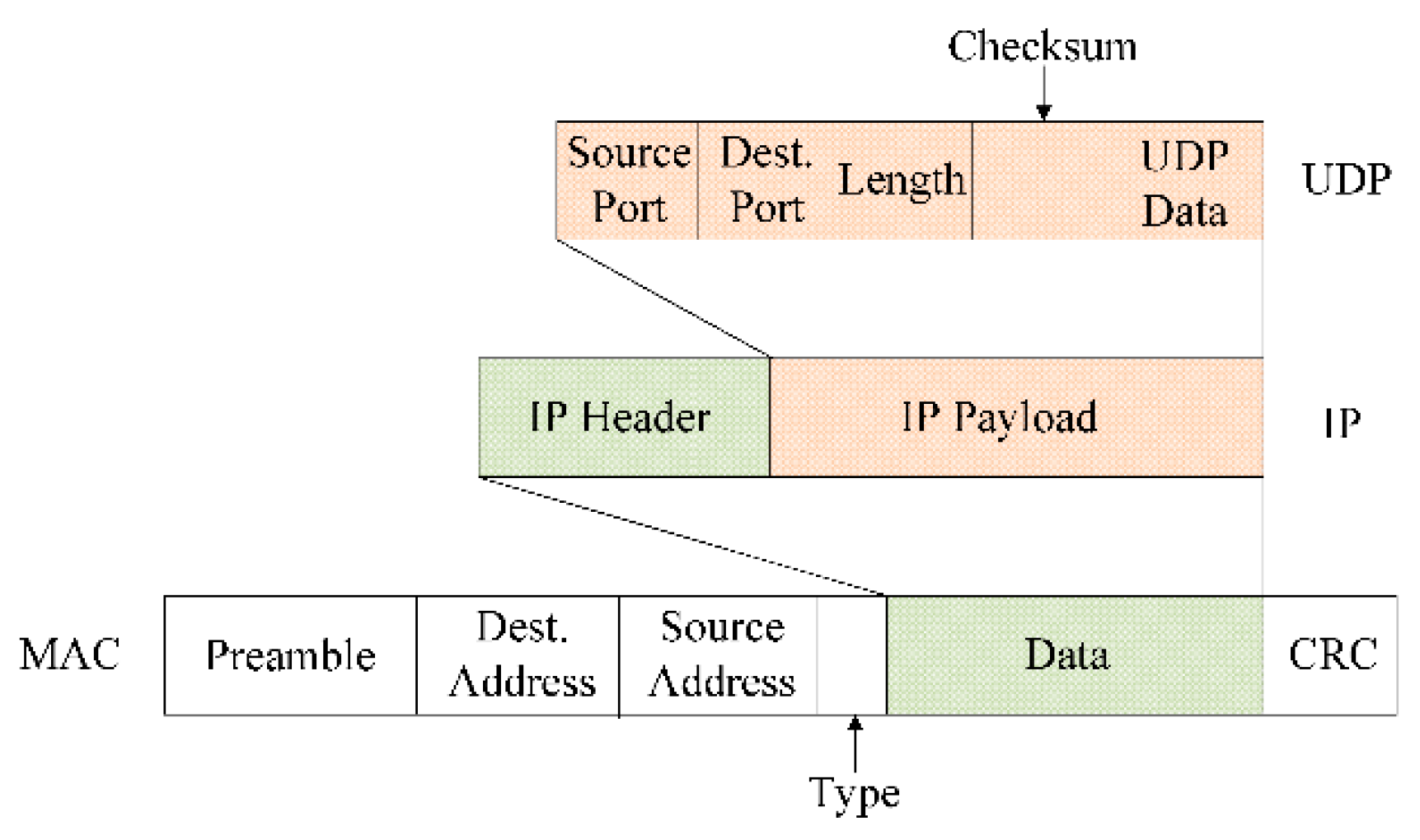
Due to the all-IP architecture of LTE-R and the broadcast sending address of the PTP, an ARP attack can easily be carried out at the data link layer during LTE-R time synchronization. The attacker becomes a middleman by forging the MAC frame structure and other means, imperceptibly inserting it into the normal communication process between eNodeB and the OBC, and maliciously tampering with or delaying the transmission of normal interactive messages randomly. This has a great impact on the synchronization accuracy of the LTE-R time synchronization process, and it seriously endangers the train operation safety and affects the real-time performance of train control systems. However, because it is difficult to find the attacker and the tampering of the message by the attacker is random and uncertain, it is difficult for the general method to accurately describe the attacker’s behavior dynamically.
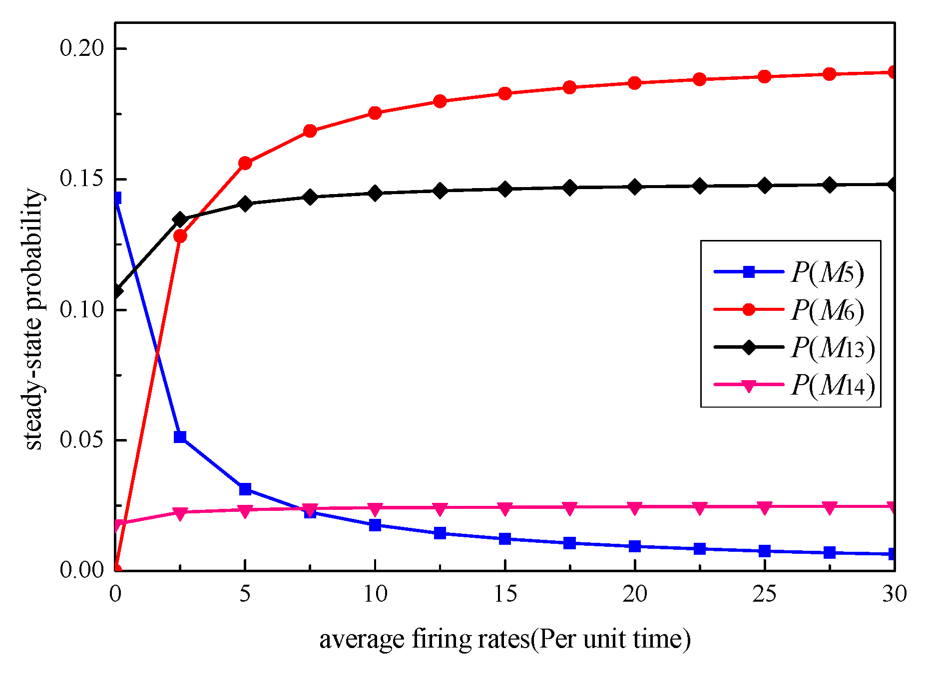
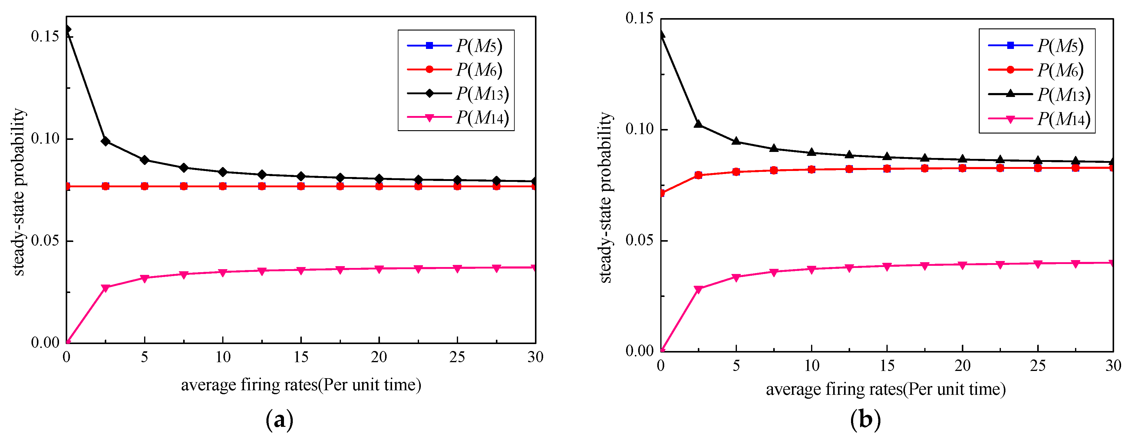
Stochastic Petri nets can build a complete LTE-R time synchronization process model under attack, restore the impact of the attack on the synchronization process, realize the vulnerability analysis of the attacker on the LTE-R time synchronization process, and then determine the most vulnerable nodes in the synchronization process. Through the special protection of these key nodes, the success rate of attacks can be reduced, and train operation safety can be better guaranteed.
4.3. SPN Model of LTE-R Time Synchronization Process
The steps to establish an LTE-R time synchronization scheme model based on SPN are as follows:
- 1.
Establish the SPN model of the LTE-R train-to-ground communication time synchronization process according to
Figure 2 and
Figure 3;
- 2.
Analyze the reachability set of the SPN model. Transform the actual transition marked on each arc into its average firing rate, and construct a continuous-time Markov chain;
- 3.
Solve the steady-state probability according to the related theorem of Markov chain stationary distribution and Chapman–Kolmogorov equations. Suppose the steady-state probability of
n reachable states is
P[
Mi] =
xi(
). Determine the element
xi in the steady-state probability set
X = [
x1,
x2, … ,
xn] using the following system of equations:
where
Q is the transfer rate matrix of the Markov process, and
n is the total number of states.
- 4.
Substitute
= {,, …,}, solve the equations, solve the stability probability of each state, and analyze the LTE-R time synchronization process according to the obtained steady-state probabilities.
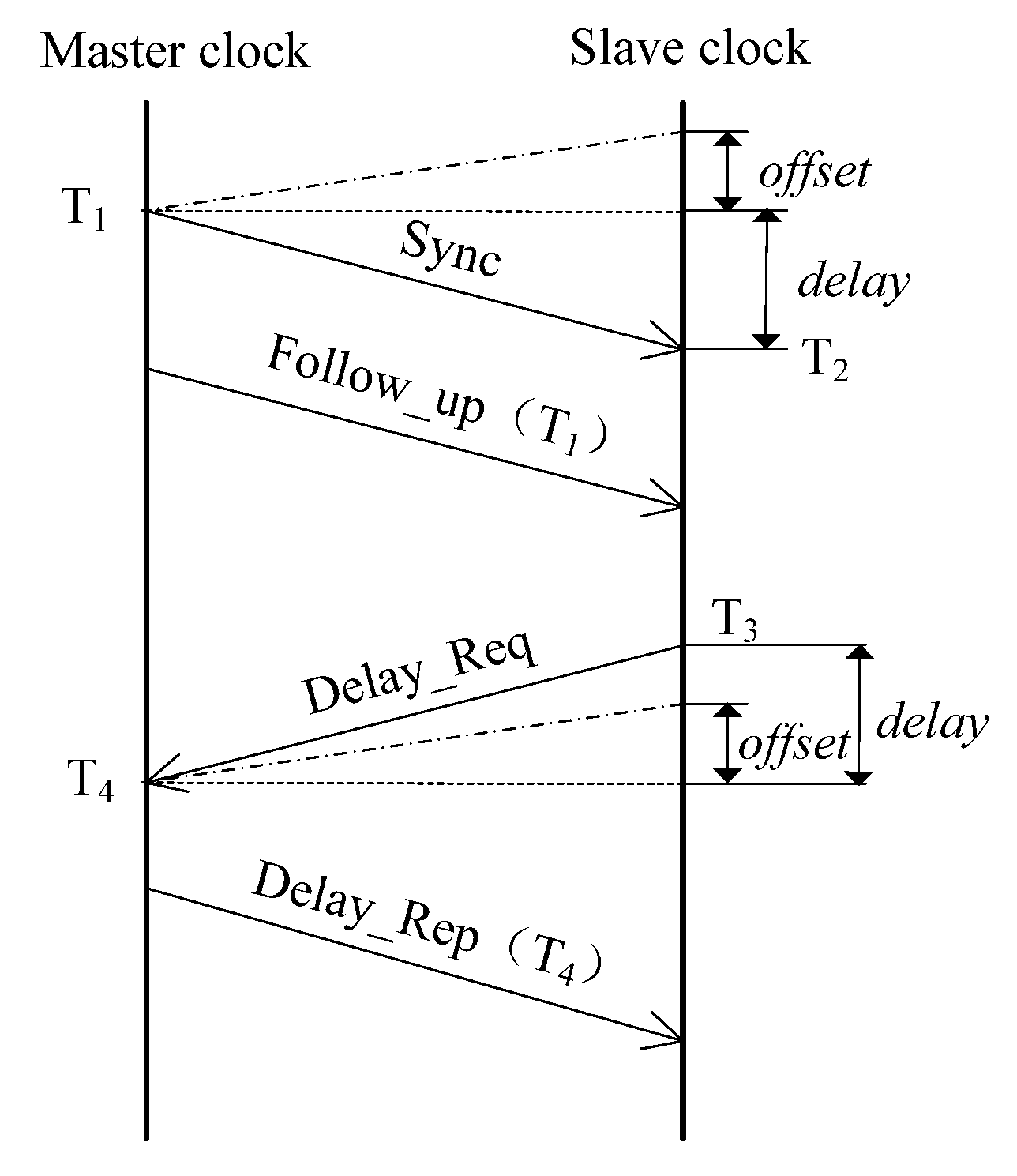
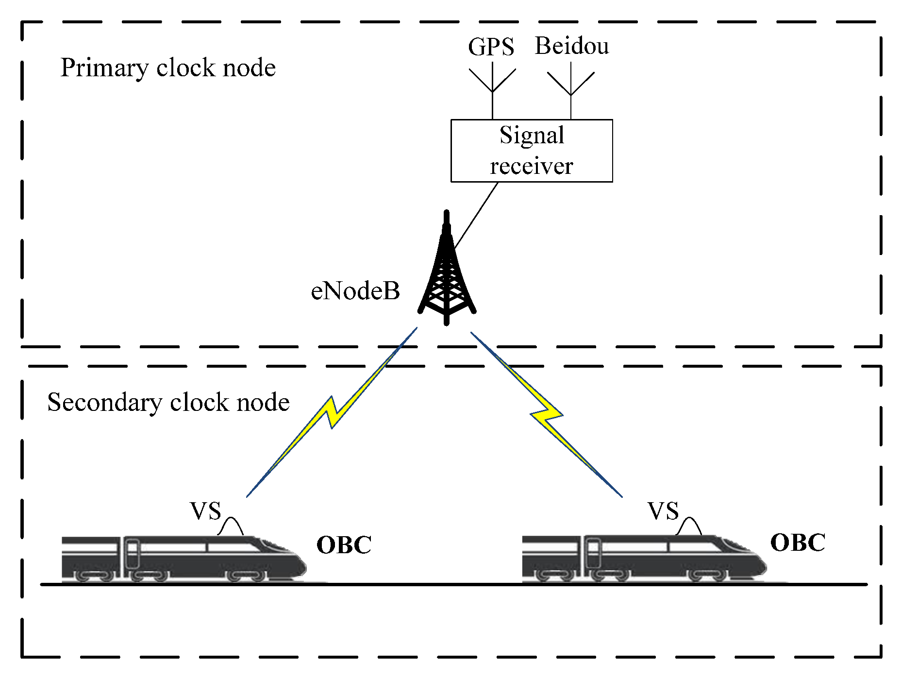
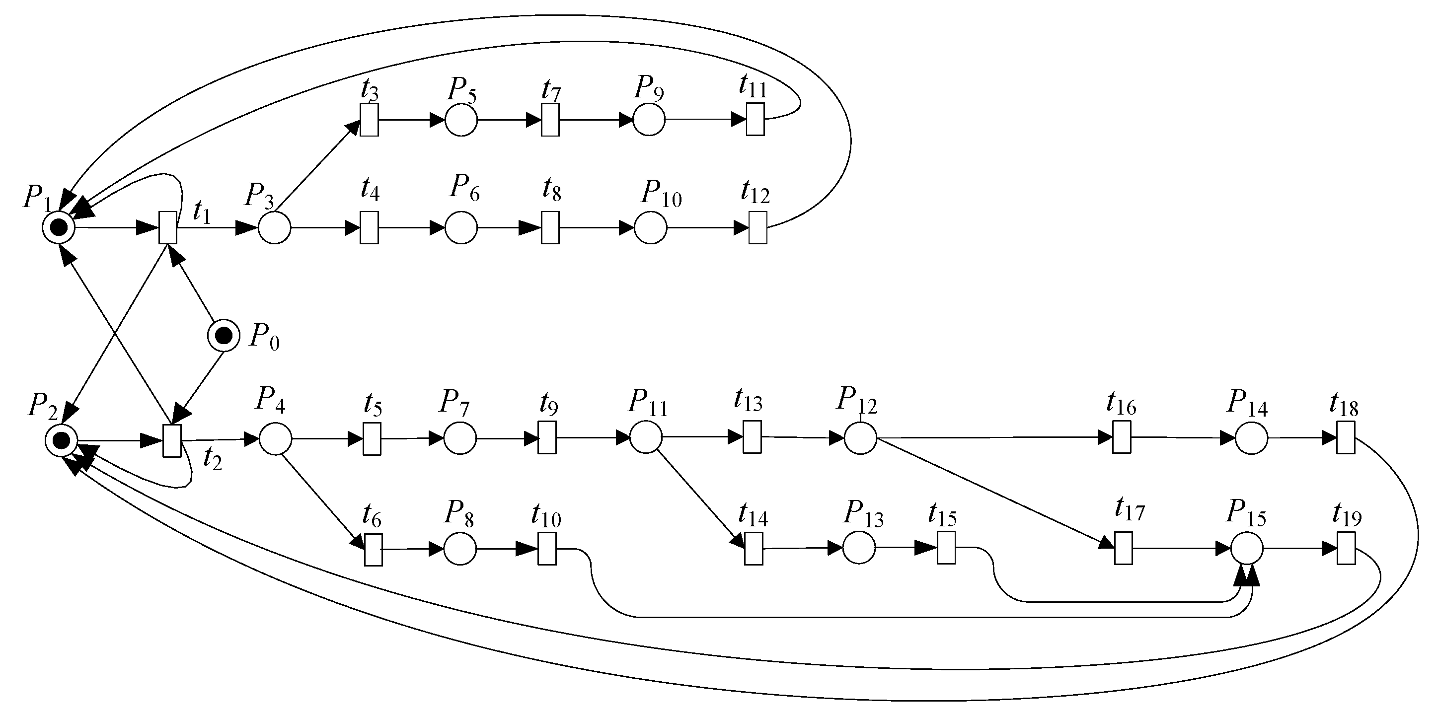
The LTE-R train-to-ground communication time synchronization process adopts a secondary clock node, in which eNodeB is the master clock and the OBC is the slave clock. They receive and forward time synchronization messages through the PTP time synchronization protocol. According to the operation mechanism of the LTE-R time synchronization PTP and the vulnerable characteristics of the PTP multicast address and all-IP architecture, a vulnerability analysis model of anLTE-R time synchronization process under attack based on the SPN theory is established. The SPN model is shown in
Figure 5. The definitions of the SPN model places are shown in
Table 1, and the definitions of transitions are shown in
Table 2.
In this model, eNodeB and the OBC establish the uplink synchronization relationship between them by performing random access processes at
t1 and
t2, respectively. According to
Section 3, the attacker
P0 can complete the ARP attack by forging the MAC frame structure, setting the destination address to the broadcast address, and modifying the message type to UDP. In this process, as a middleman, the attacker can insert themselves into the regular communication between eNodeB and the OBC and intercept the PTP message with a normal interaction timestamp. For the intercepted PTP message, the attacker can maliciously tamper with the timestamp information in the UDP data field in the MAC frame or delay the sending of the message.
In one synchronization cycle of the SPN model, the master clock node eNodeB waits to receive the Delay_Reqmessage P3 sent by the OBC. If eNodeB receives a message without timestamp information in the UDP data field of the MAC frame, it is determined that the message has been maliciously tampered with by the attacker. The synchronization cycle fails, and the token reaches the P5 state through transition t3 and finally reachese NodeB synchronization failure state P9. The synchronization cycle is completed and enters the next cycle. If a PTP message with timestamp information is received, it is considered that it has been sent by the OBC and has not been maliciously tampered with; then, the token at P3 reaches the P6 state through transition t4, and then eNodeB sends theDelay_Rep message to the OBC at t8. Finally, the token reaches the OBC completion time synchronization status P10 and enters the next cycle.
In the same cycle, the slave clock node OBC waits to receive the synchronization cycle message P4 sent by eNodeB. Similarly, if the received message has no timestamp information in the UDP data field of its MAC frame, it is determined to be a message that has been maliciously tampered with by the attacker. The OBC synchronization fails in this cycle, and the token reaches the P8 state through t6, then reaches the OBC time synchronization end failure state P15, and enters the next cycle. If there is timestamp information in the UDP data field of the received message, it is determined that the OBC has received the normal Follow_up message sent by eNodeB. Then, the token arrives at t5, OBC calculates the offset value according to the T1 and T2 timestamp information in the Follow_up message, and the token reaches the P7 state. Similarly, the OBC waits to receive the delayed response message P11 sent by eNodeB, and if there is no timestamp information in the UDP data of the received message, it is determined that the message has been maliciously tampered with; the OBC synchronization cycle fails, and the token reaches the P13 state through t14. Finally, the token reaches the synchronization failure state P15 and enters the next cycle. If a message containing timestamp information is received, it is determined to be a normal message sent by eNodeB. The token enters t13 to calculate the value of the path delay according to the received timestamp. Then, according to the synchronization deviation threshold, it is judged whether the offset and delay values are legal. If they are legal, the token enters t16, reaches the OBC time synchronization completion state P14, and enters the next cycle. If they are illegal, this indicates that the attacker launched a delay attack in the synchronization process, causing the synchronization process to fail, and the token reaches P15 and enters the next cycle.
4.4. Isomorphic MC Based on SPN
When the SPN isomorphism is a continuous-time Markov chain, the isomorphism transformation is carried out according to the following steps:
- 1.
Firstly, the firing rule between states in the SPN model is analyzed, and the marked reachable sets of all states are obtained;
- 2.
Each marking of the SPN is converted into a node corresponding to the continuous-time Markov chain reachability graph;
- 3.
The transition events between different markings in the SPN model are mapped into arcs between nodes of the CTMC reachability graph, showing the logical relationship between the different states of the system;
- 4.
Then, the transition firing rate in the SPN model is marked on each arc in the reachability graph of CTMC, and the CTMC distribution probability function is obtained.
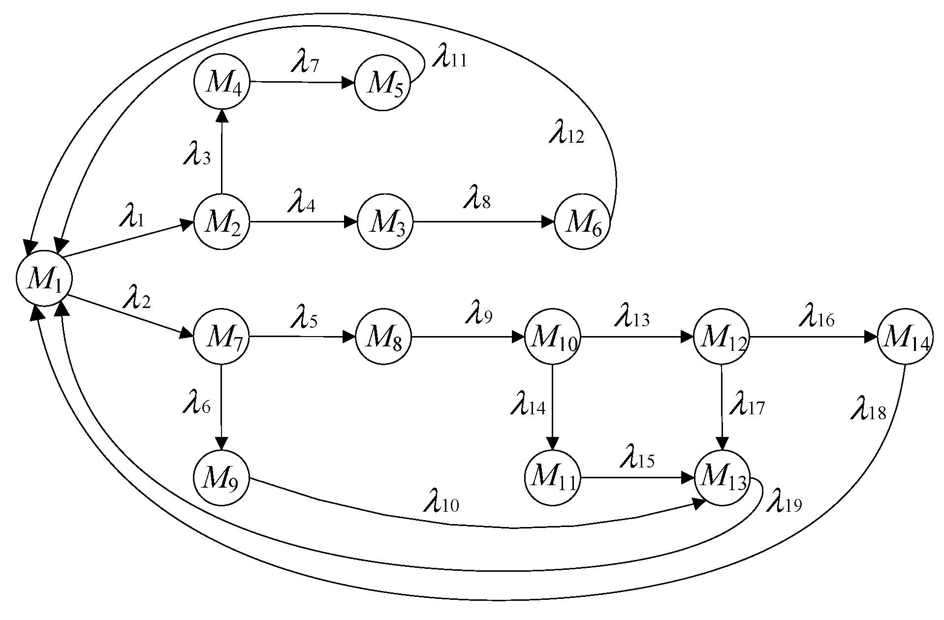
Firstly, the SPN model reachable sets are constructed.In the SPN model displayed in
Figure 5,when the LTE-R time synchronization process does not undergo an ARP attack and is in the normal operation state, there is a token in
P0,
P1, and
P2 in the model, and the initial state
M1 can be marked as
M1 = (0, 1, 2). When the attacker launches an ARP attack, the tokens at
P0,
P1, and
P2 begin to move. According to the relationship between the different transition events of the SPN model in
Figure 5, the following state reachable sets can be obtained:
M2 = (1, 2, 3),
M3 = (1, 2, 5),
M4 = (1, 2, 6),
M5 = (1, 2, 9),
M6 = (1, 2, 10),
M7 = (1, 2, 4),
M8 = (1, 2, 7),
M9 = (1, 2, 8),
M10 = (1, 2, 11),
M11 = (1, 2, 13),
M12 = (1, 2, 12),
M13 = (1, 2, 15), and
M14 = (1, 2, 14).
M1–
M14 are 14 states of the LTE-R time synchronization SPN model, including the eNodeB abnormal end state
M5, eNodeB normal end state
M6, OBC abnormal end state
M13, and OBC normal end state
M14. According to the SPN model, they are transformed into the nodes of the CTMC reachability graph.
Then, the transition events
ti converted between the different markers in the SPN model are mapped to the arcs between the nodes of the CTMC reachable graph, and the firing rates
λi are correspondingly marked on each arc in the CTMC reachable graph.
λ1–
λ19 are the average firing rates between the different states in the SPN model. The average firing rate of the different states
λi (
i = 1, 2, …, 19) depends on the occurrence of different changes. If a directed arc is used to represent the transformation of different marks or states, an MC equivalent to the SPN model can be obtained, as shown in
Figure 6.


