
Optomechanical Analysis and Design of Polygon Mirror-Based Laser Scanners


Abstract
Featured Application
Abstract
1. Introduction
2. Characteristic Functions and Parameters of PMs versus GSs
2.1. GSs and PM Scanning Heads
2.2. Characteristic Functions of GSs and PM Scanning Heads
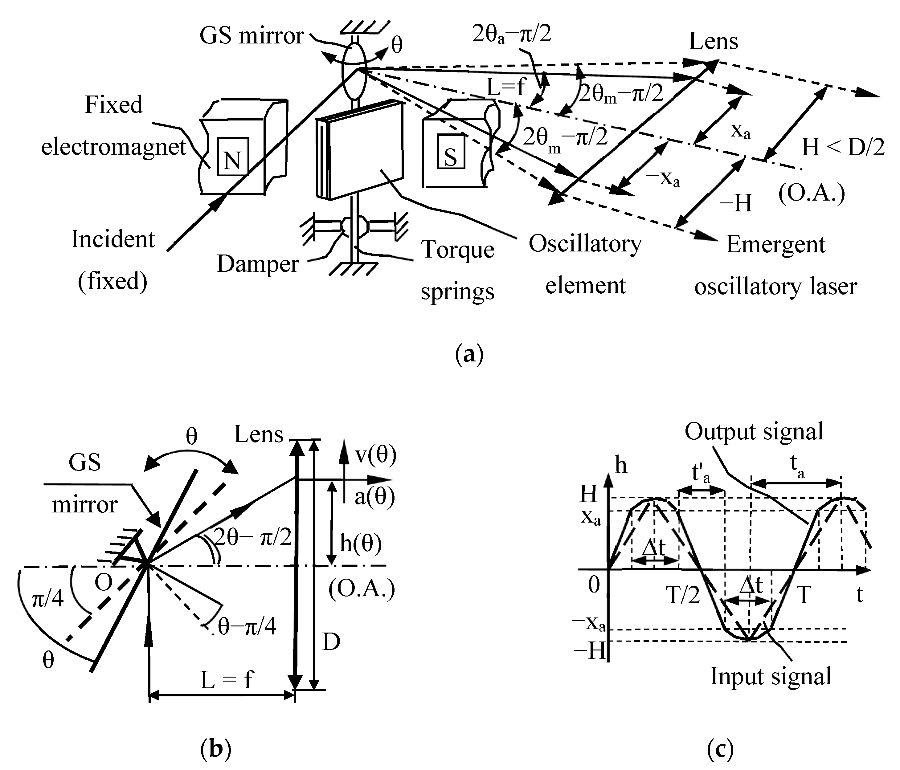
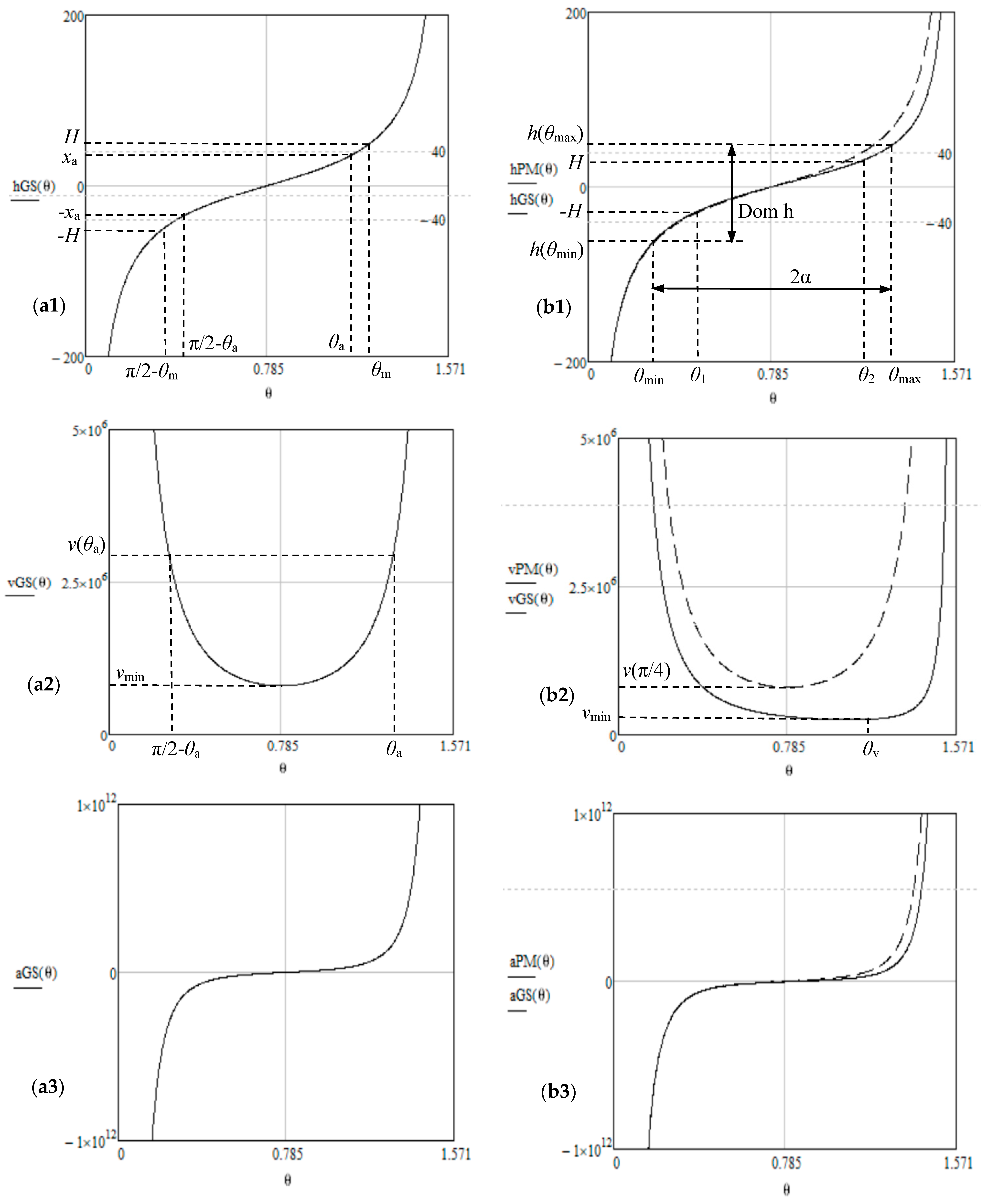
- For a GS, the start position of the GS mirror is at π/4 [rad] with regard to the horizontal axis Oz. As the mirror rotates with θ, the reflected beam rotates with 2θ, therefore the scanning function would be h(θ) = L·tan2θ. While this simple equation is usually utilized for GSs [7,9,10], in the present study, to allow for a comparison to PMs, the θ = 0 position is considered for a horizontal position of the GS mirror (when the reflected beam would be superposed to the incident one), as previously pointed out. In this case, the scanning function results in being h(θ) = −L/tan2θ, therefore the scanning velocity and acceleration have Equations (2) and (3), respectively (Table 1). The graphs of these three functions are presented in Figure 3a.
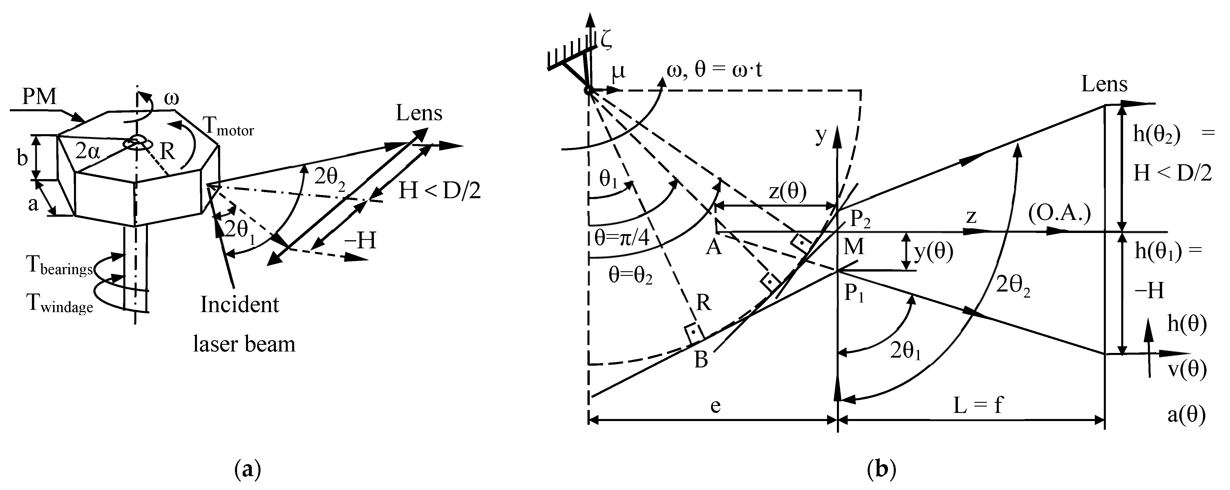
- For a PM scanning head, a facet is represented in three positions in Figure 2b, considering θ = 0 for the facet in a horizontal position. Similar to GSs, the rotational angle θ = π/4 defines the facet position in which the (fixed vertical) incident beam is reflected on the (horizontal) Oz axis, which defines the O.A. of the lens. For θ1 and θ2 (with θ1 < π/4 < θ2), the reflected beam reaches the inferior and superior margins of the lens in the meridian plan Oyz, therefore h(θ1,2) = H (where H < D/2), Figure 2. Points P1, M, and P2 are the intersections of the incident ray with the PM facet for these three rotation angles considered (i.e., θ1, π/4, and θ2, respectively). For a current rotational angle θ, from Appendix A, the scanning function is deduced, with Equation (4), therefore the scanning velocity and acceleration are obtained with Equations (5) and (6), respectively (Table 1). An experimental validation of this PM scanning function was completed in [32].
- The comparison of each corresponding pair of functions (i.e., for GSs and PMs) is performed in Figure 3b, on a numerical example with L = 40 mm, R = 15 mm, e = 6 mm, and ω = 10 krpm (the latter corresponding to an idle rotation of the PM). The asymmetry of the PM functions graphs can be remarked, in comparison to the symmetry of (dotted graphs of) GS functions—to be discussed in Section 3.
2.3. Migration Functions
2.4. Scan Angles and Angular FOV
- For a GS, shown in Figure 1a, the total rotational angles interval is [π/2 − θm, θm] (Equation (9), Table 1) and the useful rotational angles interval is [π/2 − θa, θa] (Equation (10), Table 1), with the latter corresponding to the portion scanned with constant velocity [9,10]. Therefore, the angular FOV could be considered with either its useful value, 2θa − π/2, or with its total one, 2θm − π/2, Equation (11), Table 1.
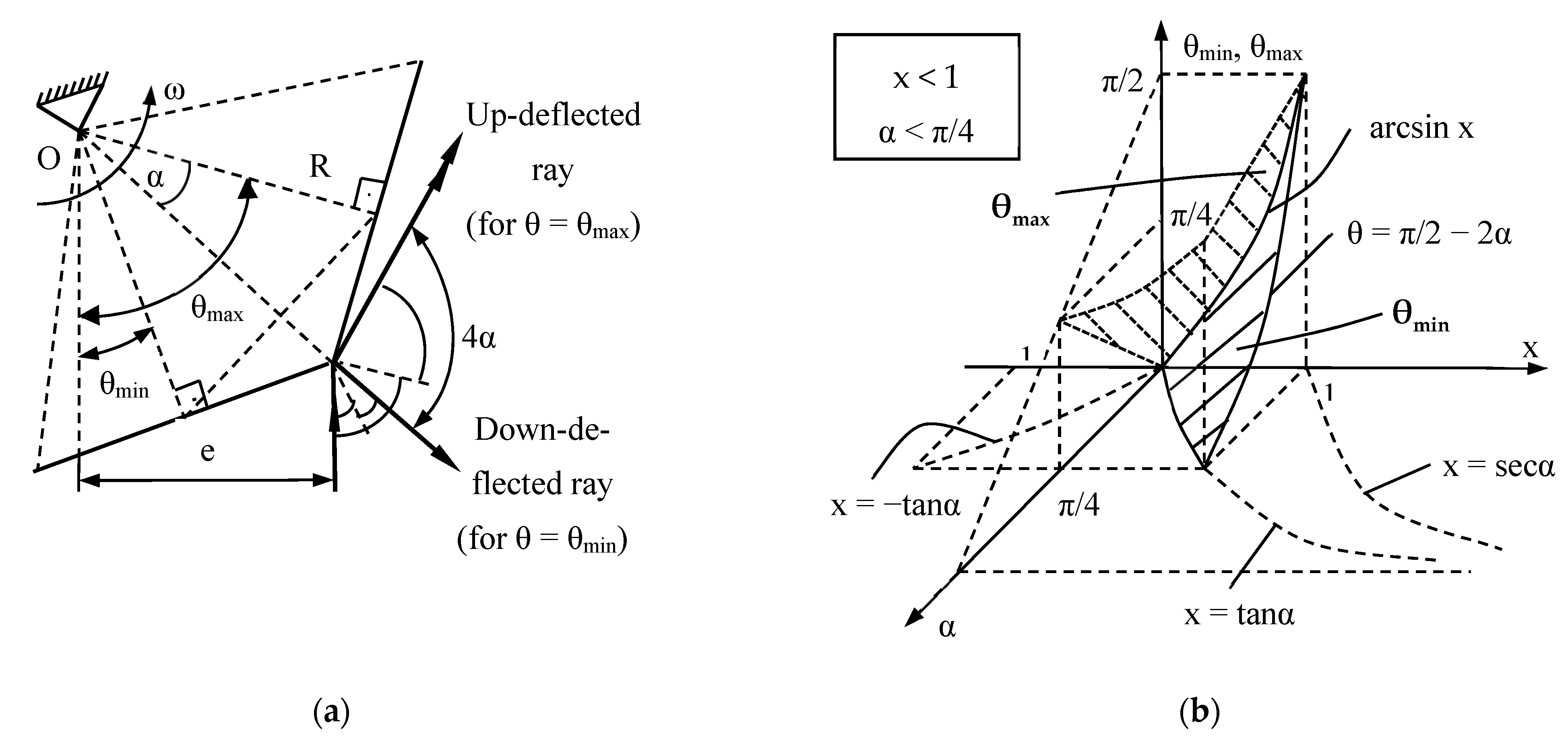
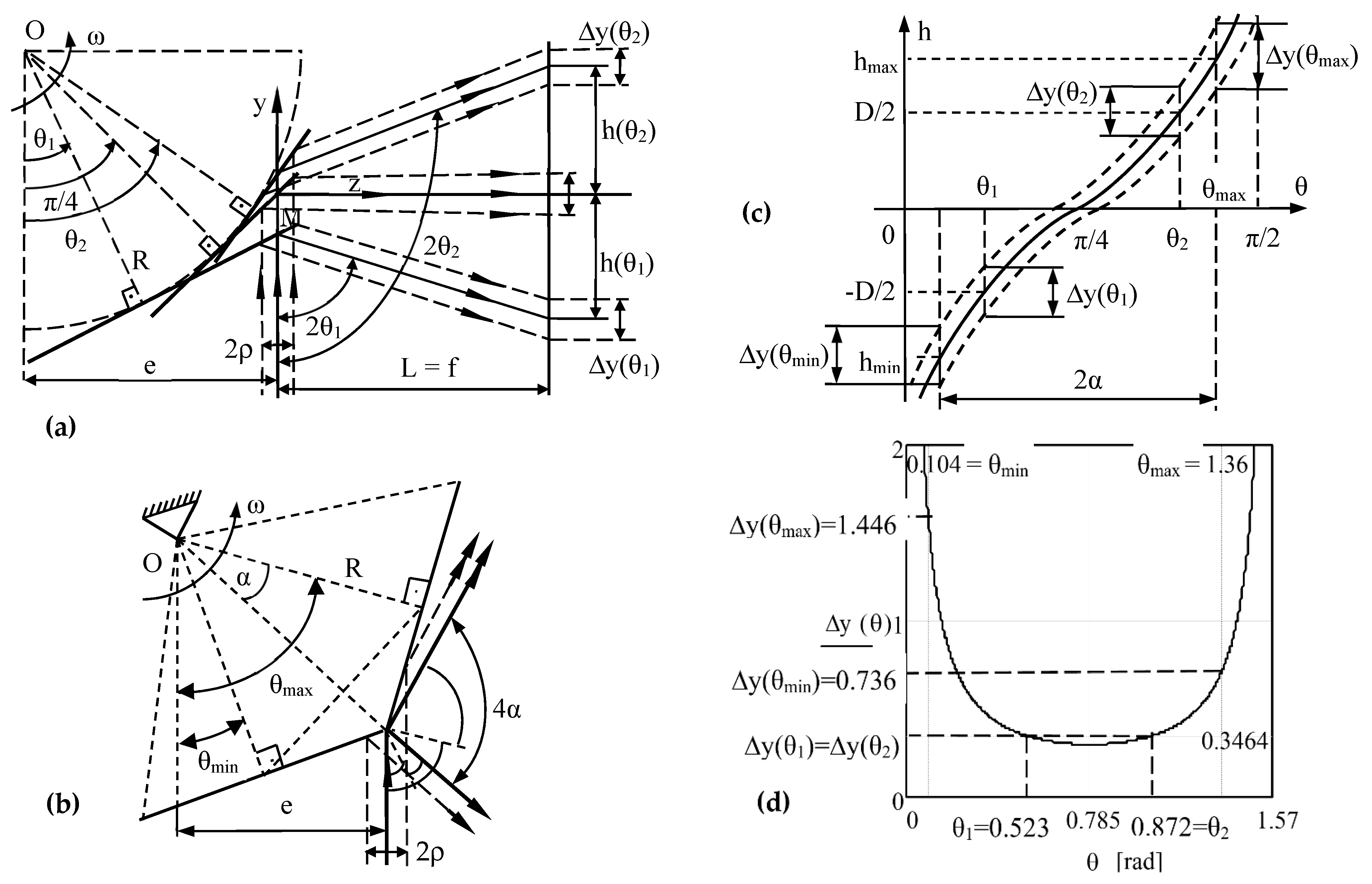
- For a PM, two pairs of scan angles are important: θ1 and θ2, which define the useful angular FOV, as discussed in Section 2.2—Figure 2a,b; θmin and θmax, which define the down-reflected and up-deflected positions of the reflected beam of a scanner (in a concept introduced by Beiser [2]), therefore the total possible FOV—Figure 5a. To characterize these latter beams for a PM, we introduced the construction in Figure 5a [29,32], where the reflection is considered at the beginning and end of a PM facet (without referring to the vignetting produced by the finite beam diameter). From this figure, these two reflected beams are characterized bytherefore the expressions of the two (extreme) scanning angles are given by Equation (12), Table 1. These equations also give the total angular FOV of the PM—Equation (14), Table 1. The values of the useful angles θ1 and θ2 are obtained by solving Equation (13), Table 1.

2.5. Linear FOV
- For a GS, using Equation (1), the linear FOV (i.e., the maximum dimension that can be scanned on a certain target plane/lens) is obtained, with Equation (15), Table 1.
2.6. Duty Cycle
- For a GS, the duty cycle cannot be, for example, (as one may consider at a rapid glance), as the extreme angular intervals (i.e., the stop-and-turn portions between and , as well as between and ) are not scanned with a constant velocity, even for a triangular input signal, as shown in the example in Figure 1c. Therefore, for such a signal, Equation (17) in Table 1 is the appropriate one for low fs, while Equation (18) in Table 1 is appropriate for high fs, as studied in detail in [9,10]. For sawtooth input signals, the discussion is similar, and one must differentiate between the theoretical duty cycle (Equation (13) in Table 1) and the effective one (Equation (14) in Table 1) with regard to fs, as discussed in [7,8,9]. These values of the duty cycle can be improved with the use of (rather expensive) F-theta lenses, to linearize the scan, but we have shown that even a well-calculated (and cost-effective) achromatic doublet can be utilized for certain GS-based setups [54].
- For PM scanning heads, this problem of the duty cycle is less complicated, because the rotational velocity ω of the PM is constant. Therefore , and this gives the final Equation (19) in Table 1. One must point out that this is “n” times higher than for monogon scanners (i.e., pyramidal PMs with a single facet), which seemed to make a comeback in the context of developing fast rotational scanning heads that may avoid the use of an objective lens [61,62].
- For both GSs and PMs, due to the finite diameter of the beam, is also affected by vignetting at the margins of a facet/mirror [26]—an effect minimized by placing the incidence point in (for GSs) or around the object focal point (for PMs).
3. Multi-Parameter Optical Analysis and Design of PM Scanning Heads
3.1. Scan Angles and FOV
- (a)
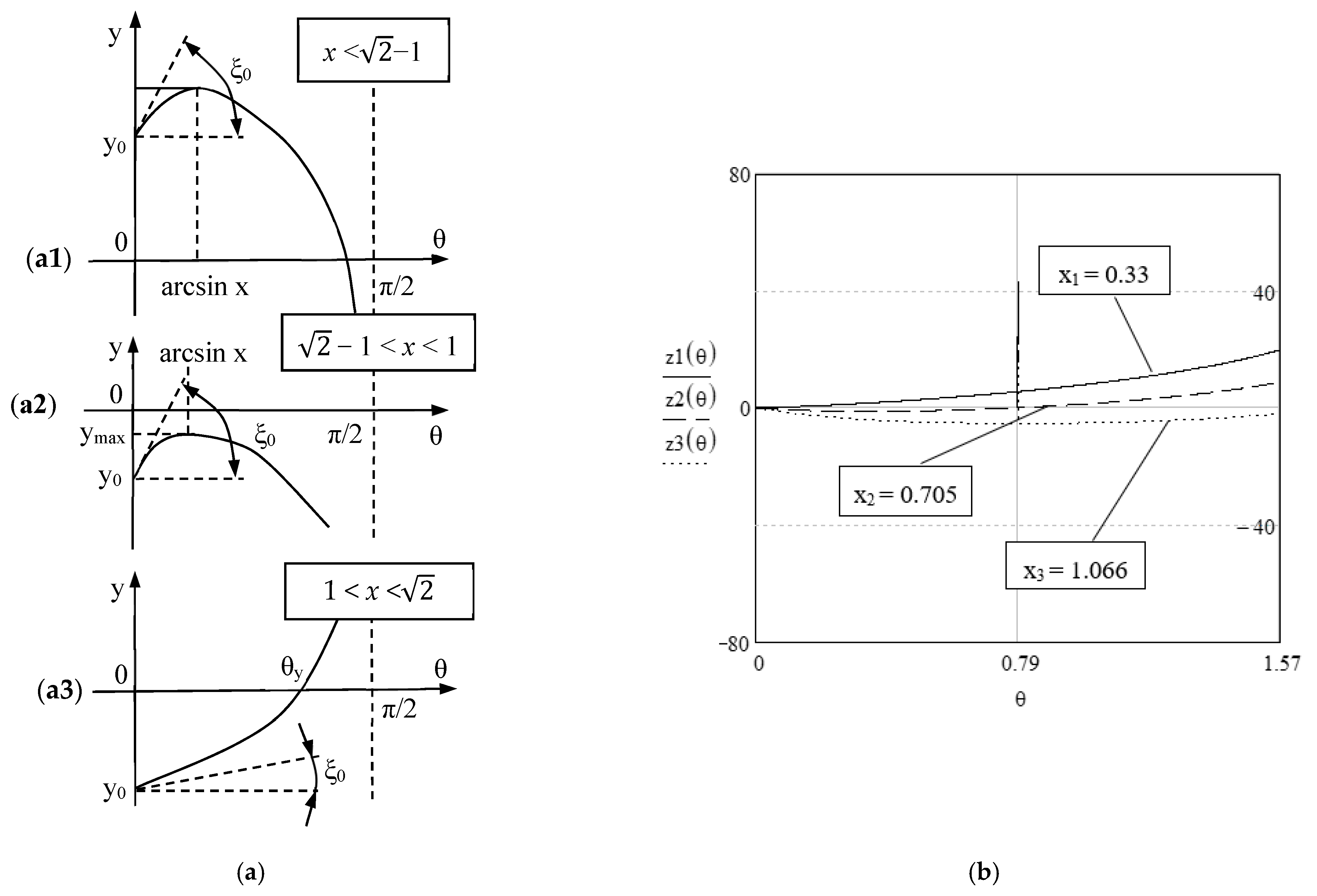
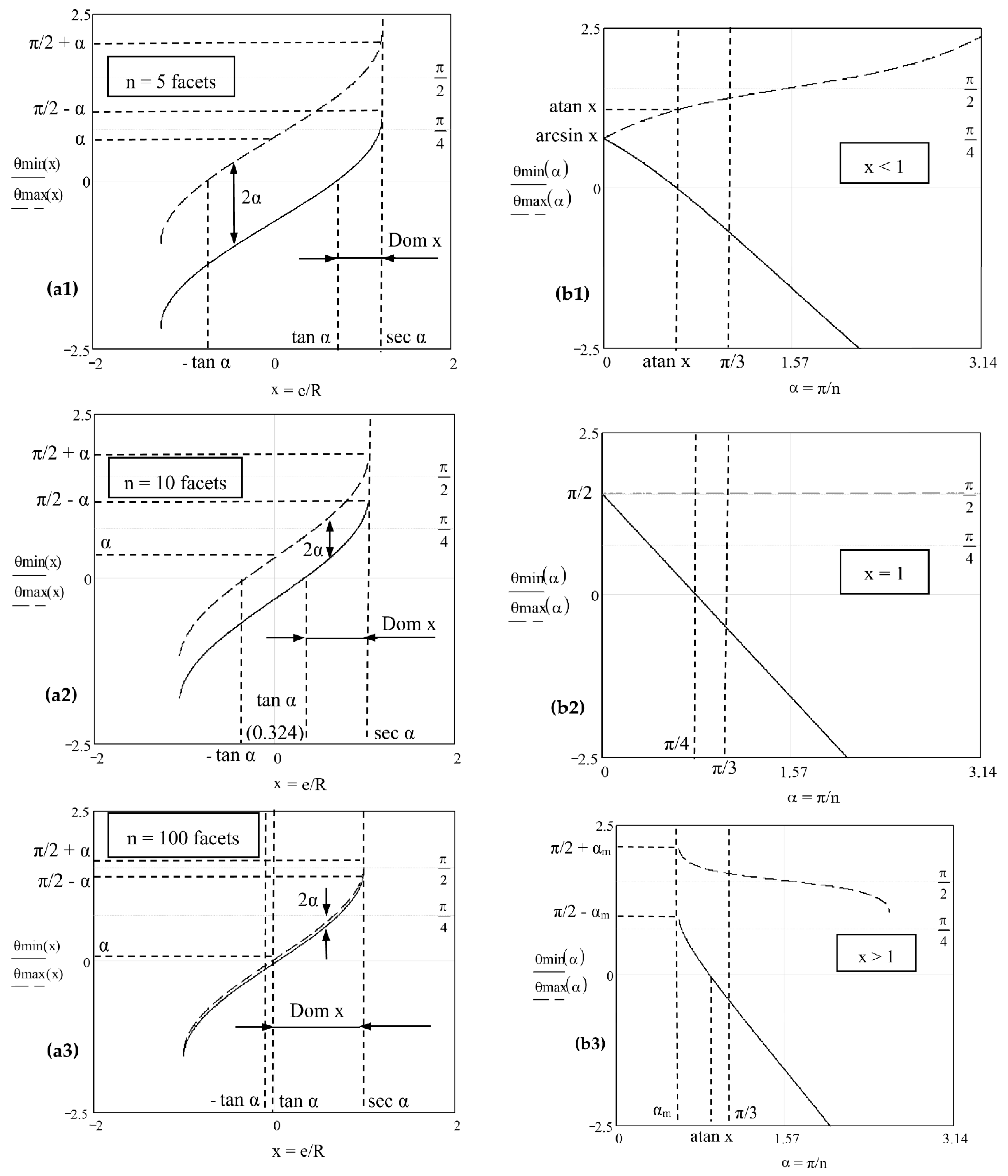
- From the study with regard to the parameter x, Figure 6a:
- -
- Three values of n are considered, from n = 5 (i.e., for a pentagonal PM utilized, for example, in commercial or industrial applications such as printers or handheld probes) to n = 10, and finally, to n = 100, with the latter being specific, for example, to high-end applications such as PM-based SSs [19,20,21,22,23,24,25,26]. One can observe the way the 2α = FOV/2 difference between the two scan angles decreases with n.
- -
- Regardless of the particular values of n, the possible domain of the parameter x has a lower limit equal to tan α (for which and ) and an upper limit equal to (from which both and are not defined anymore). At the limit,
- (b)
- From the study with regard to the angle α, Figure 6b:
- -
- Two specific intervals of the parameter x, smaller and larger than 1, are considered, as well as the particular case x = 1. Although and are considered as functions of the angle , the rows of values of the two angles are actually relevant, as only integer values of the number n of facets correspond to reality.
- -
- A useful limit value of α is π/3, corresponding to 1 < x < . However, as observed above, the case of a too high x (for a small n) must be avoided, to minimize vignetting. Therefore, in practice, n is equal to 4 or higher, as discussed in another context in [32]. An exception may be the n = 2 case (of a plane or pyramidal rotational mirror with two facets) or the n = 1 case (of the pyramidal monogon).
3.2. Duty Cycle
- (i)
- (ii)
- η = 1 is a difficult condition to apply. It is fulfilled forand it means that the O.A. is no longer perpendicular to the incident ray, because the FOV is, in general, asymmetric with regard to the horizontal axis. From Figure 5a, using Equation (12), the particular case of the symmetry of the down-reflected and up-reflected rays with regard to the horizontal can be achieved for:
- (iii)
- η > 1 corresponds to a lens with a diameter D larger than the linear FOV. This may be the case of a PM with a large n. From Figure 6, for a small angle α, the angular FOV = 4α narrows—see, for example, Figure 6(a3). In practice, this case is applicable for double-pass PMs [1, 2], for which the incident beam is split in two. For such a configuration, the scan of the following PM facet begins before the scan on the current facet is completed. In this case .
3.3. Scanning Function and Velocity
- (a)
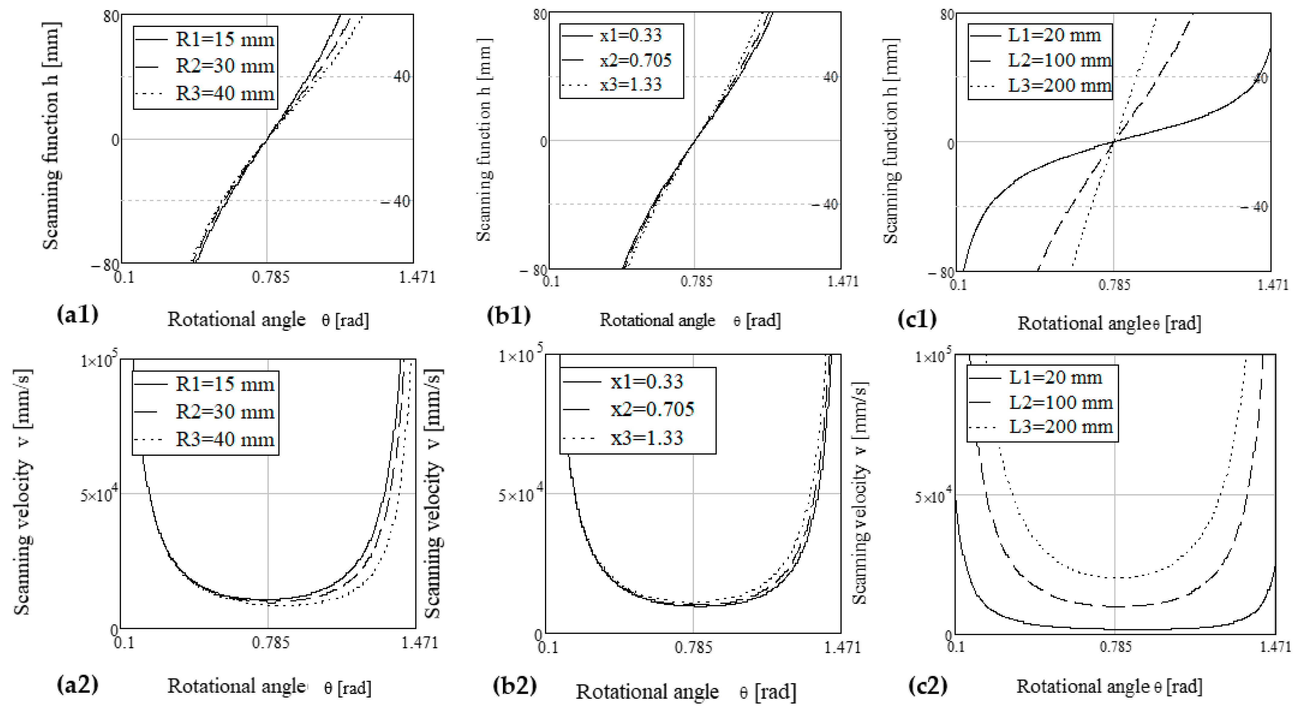
- The apothem R is considered from 15 to 40 mm, although smaller values are also utilized in practice (e.g., for square PMs in printers), while higher values of R are necessary for large PMs utilized in high-end applications for which high fs values are acquired. To achieve the latter, the PMs must have a high n, therefore R must be large to keep the facet aperture over a useful threshold (to accommodate a laser beam of a certain diameter and minimize the negative effect of vignetting). It can be observed that a larger R means a better linearity of the scanning function h(θ) and an approximate constant scan velocity v(θ) over a slightly larger domain of θ, therefore such an R is advantageous. However, it also implies a trade-off with structural aspects, as approached using FEA in Section 5.
- (b)
- The parameter x = e/R is considered with three values, corresponding to the three characteristic cases considered in Figure 6, as well for x < 1 or x > 1, and with their in-between limit case x = 1. As at the previous point, a slightly more linear h(θ) and more constant v(θ) over a larger domain of θ can be obtained with a smaller x, i.e., for the x < 1 case. This result is in good agreement with the discussion on the scan angles and the most advantageous case from that point of view—Figure 6(b1).
- (c)
- The distance L is considered from the small value of 20 mm, which allows one to capture a large part of the graph of the scanning function and to highlight its non-linearity—as observed in the experimental study in [32], as well. The largest considered dimension of L is 200 mm, which may require folding the beam, as addressed further in Section 4. As L = f (Figure 2), a more common value of L would be approximately 40 mm, as considered in Figure 3b, to have a reasonable dimension of the scanning head. However, for such a value, the non-linearity of h(θ) is already manifested for common values of the scan angles (i.e., FOV), therefore the solution developed in Section 4 is useful, as well.
3.4. Migration Functions
3.5. Rules-of-Thumb for the System Design
- (i)
- (ii)
- The x < 1 interval in Figure 6(b1) is the one that applies to the angles θmin and θmax studied as functions of the angle α.
- (iii)
- The conditions θmin > 0 and θmax < π/2, which are necessary to increase the duty cycle, Equation (12), Table 1, provide n ≥ 5, therefore at least a pentagon PM must be used for this scanner configuration.
3.6. Spot Variations Due to the Finite Diameter of the Laser Beam
4. Linearization of the Scanning Function
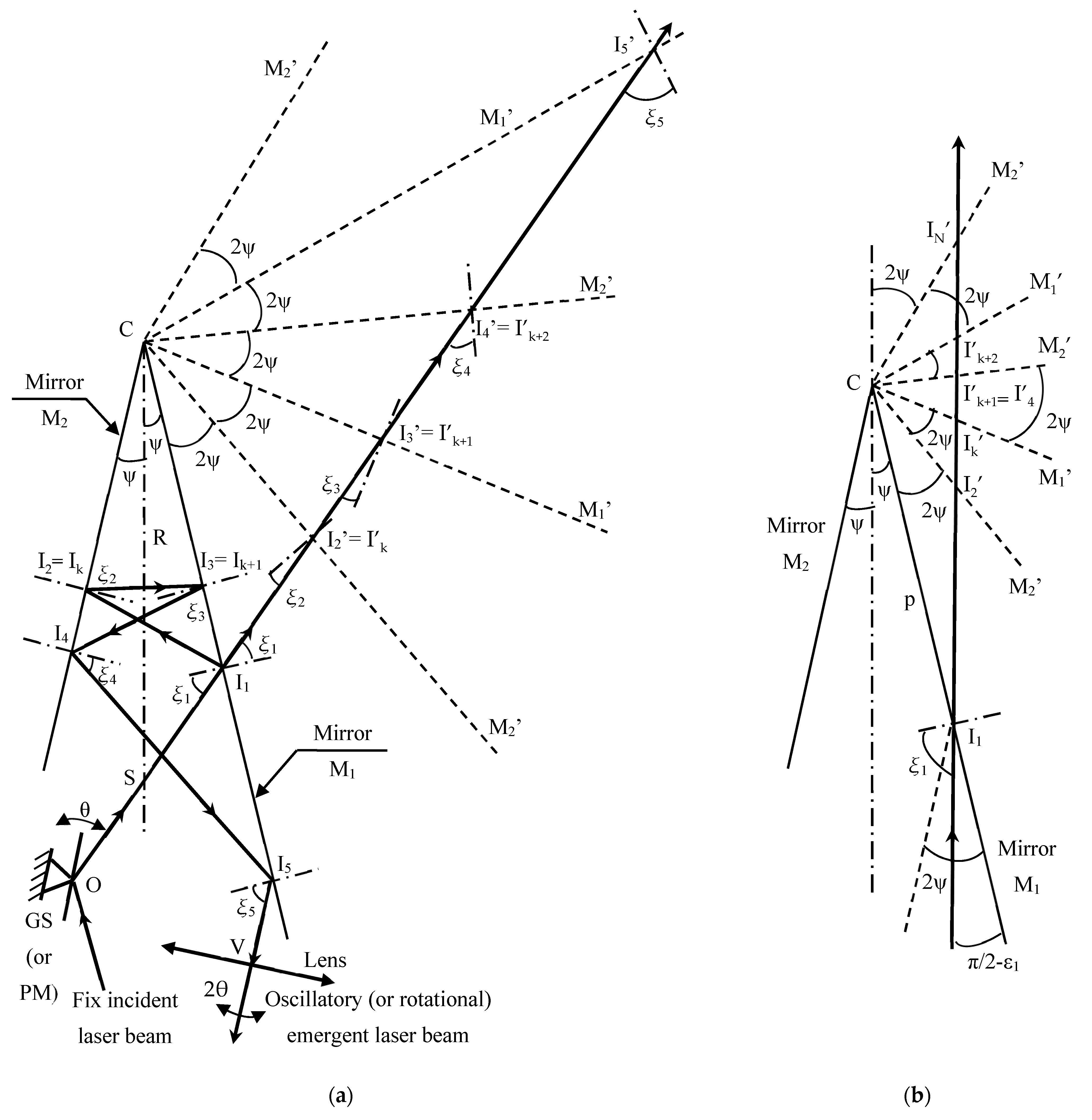
4.1. The Two-Mirrors Angular Device
4.2. The Incidence (and Reflection) Angles
4.3. The Returning Incidence Point
4.4. The Positioning of the Two Mirrors of the Device
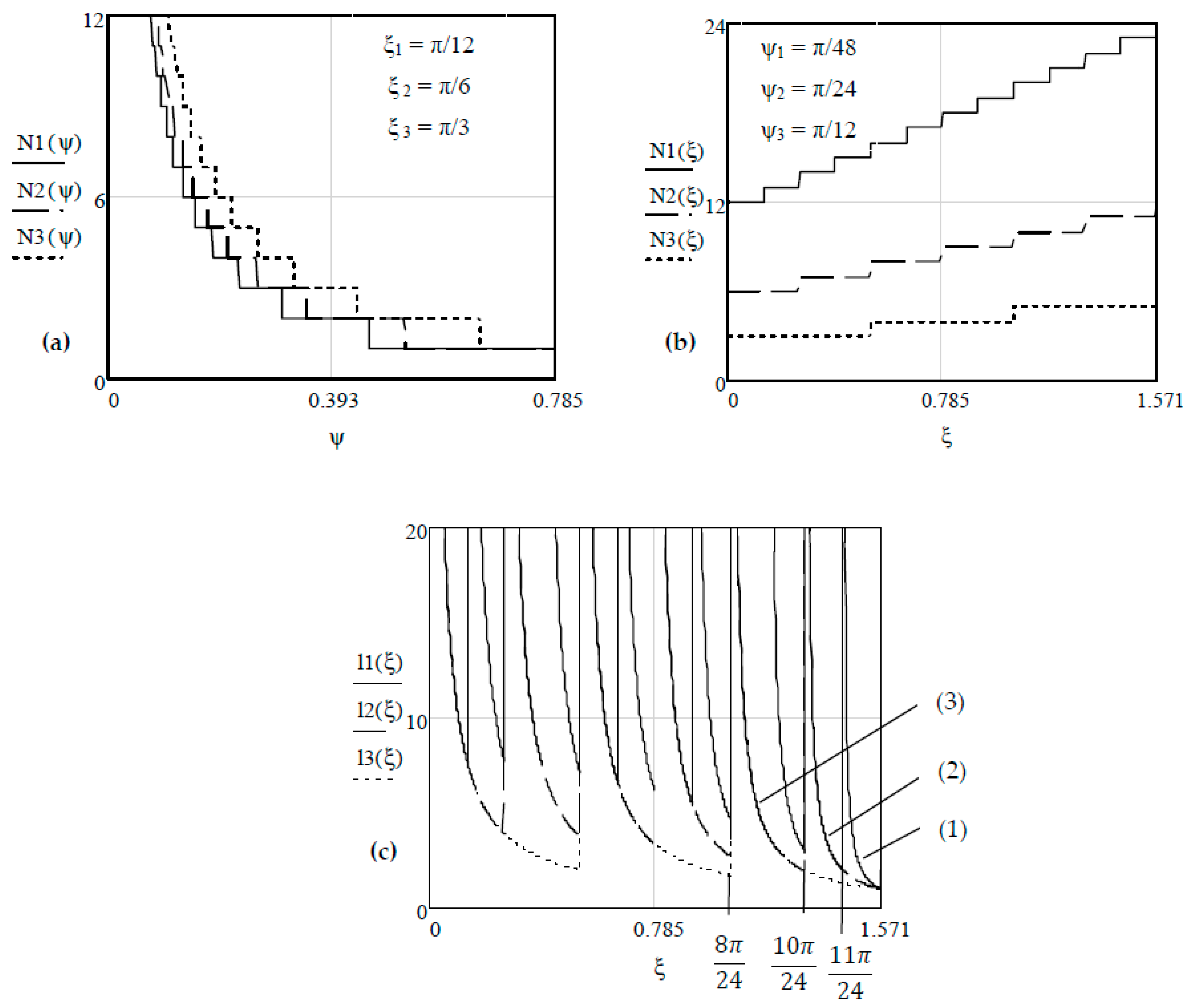
4.5. The Maximum Number of Reflections (N)
4.6. The Maximum Possible Value of the Distance L
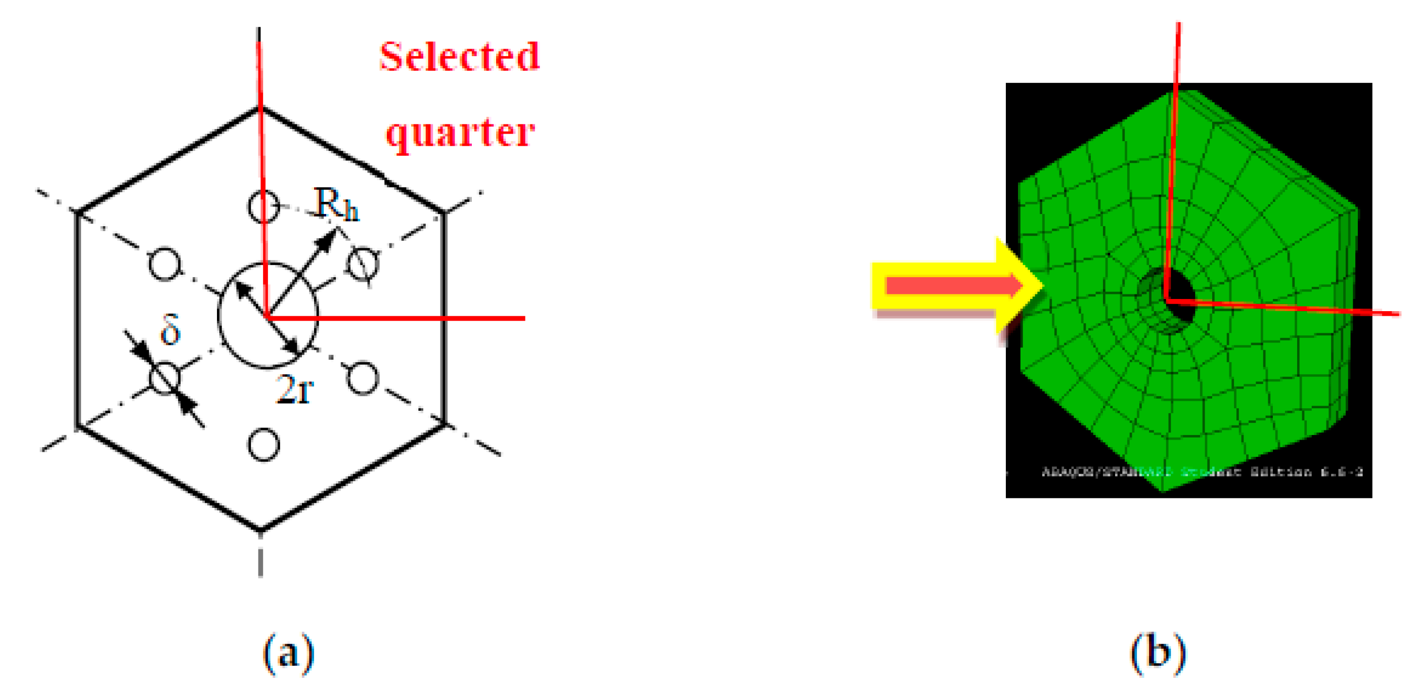
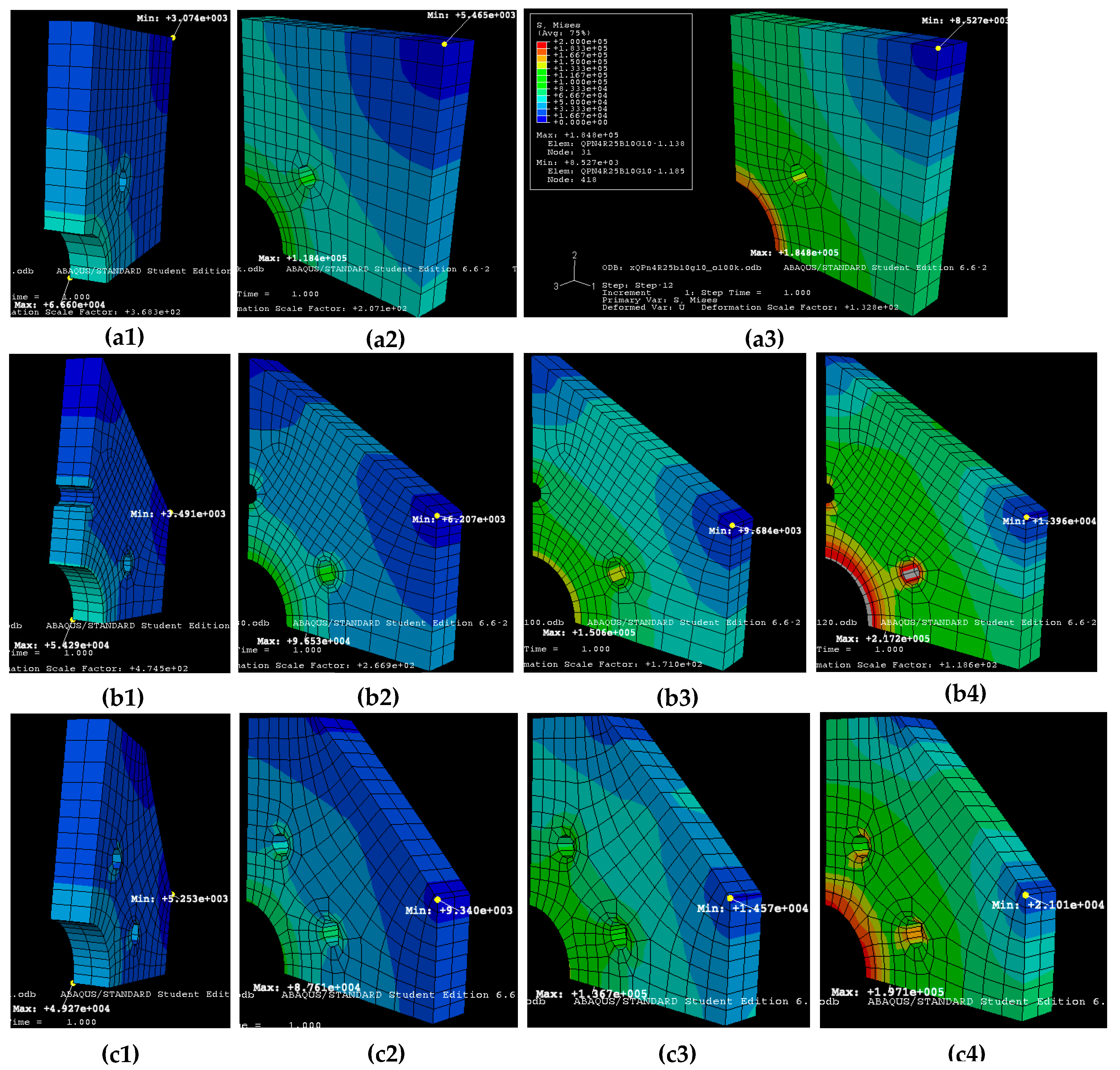
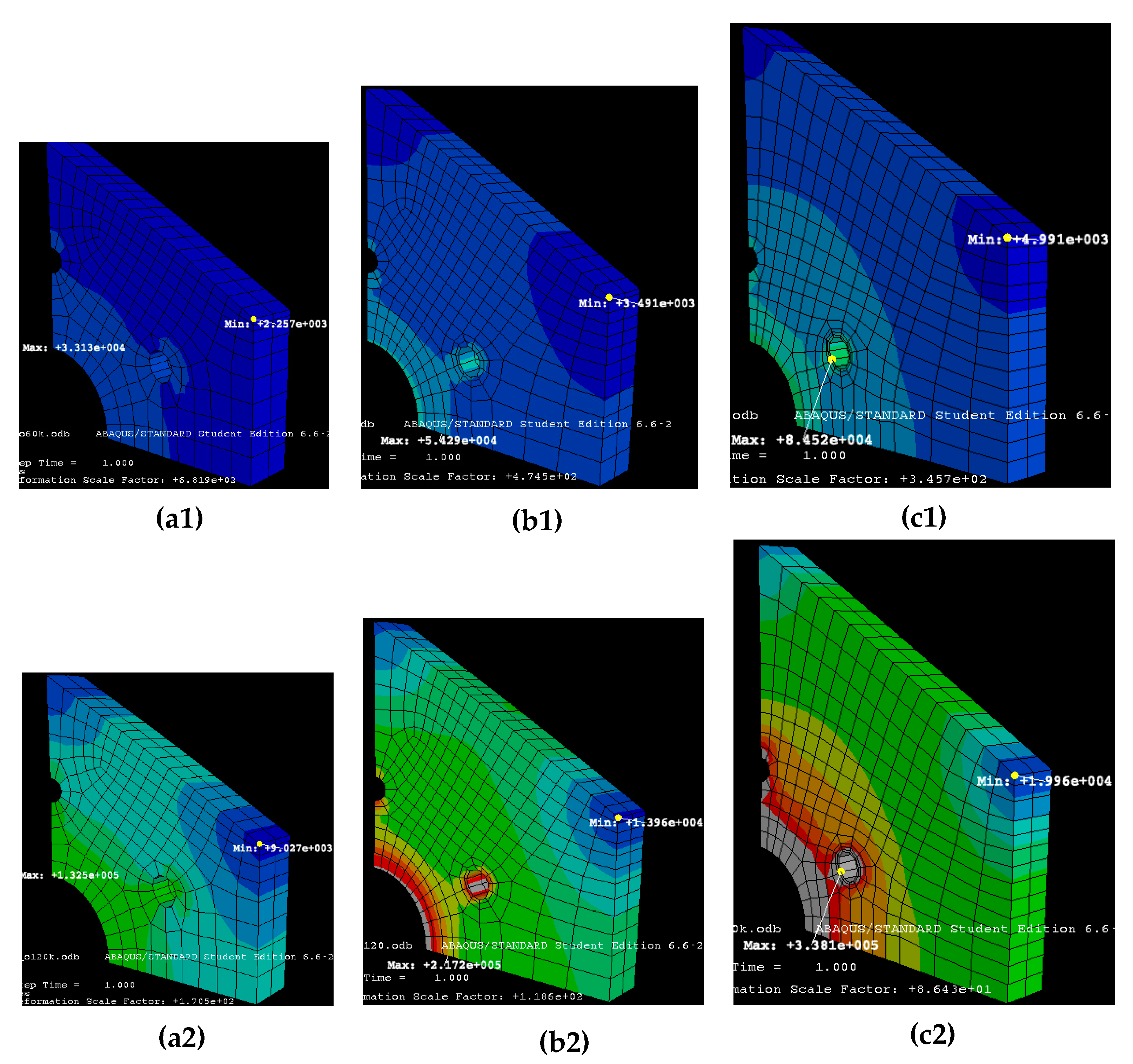
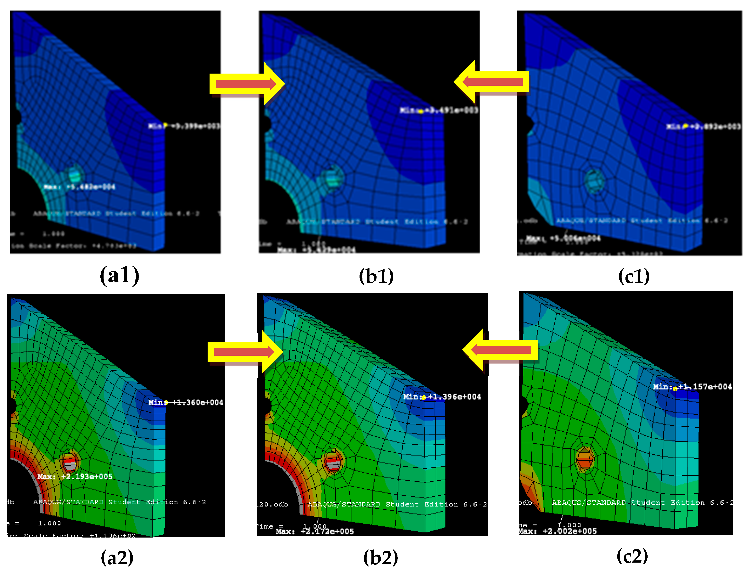
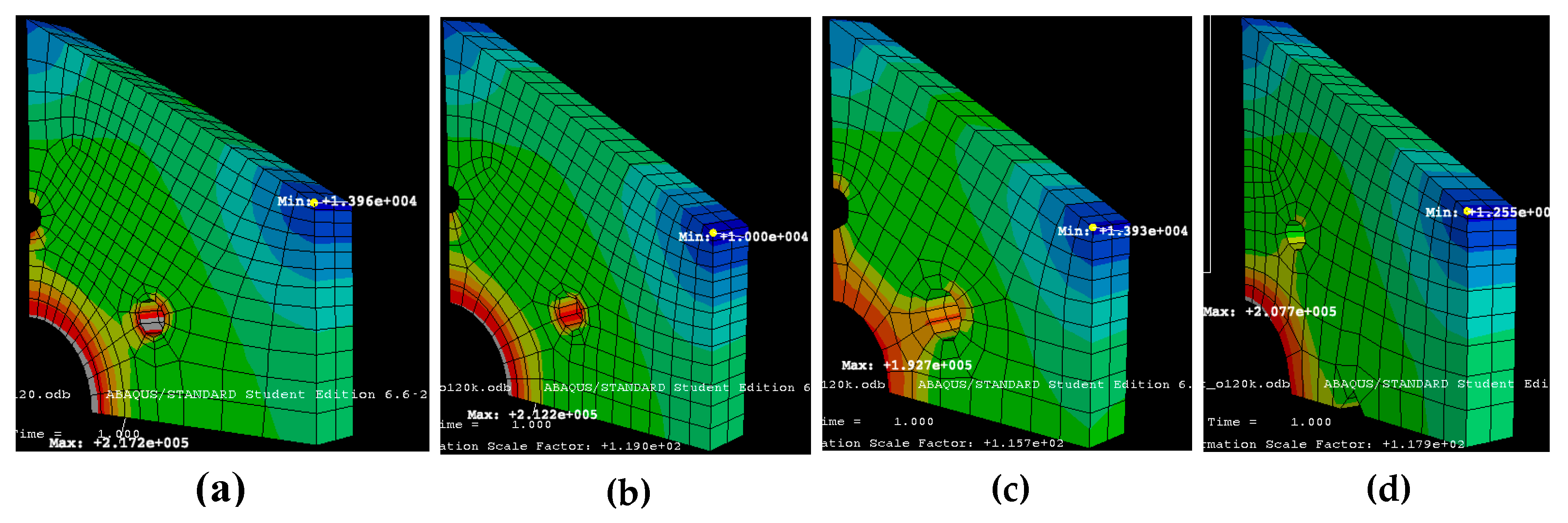
5. Finite Element Analysis (FEA) of PMs
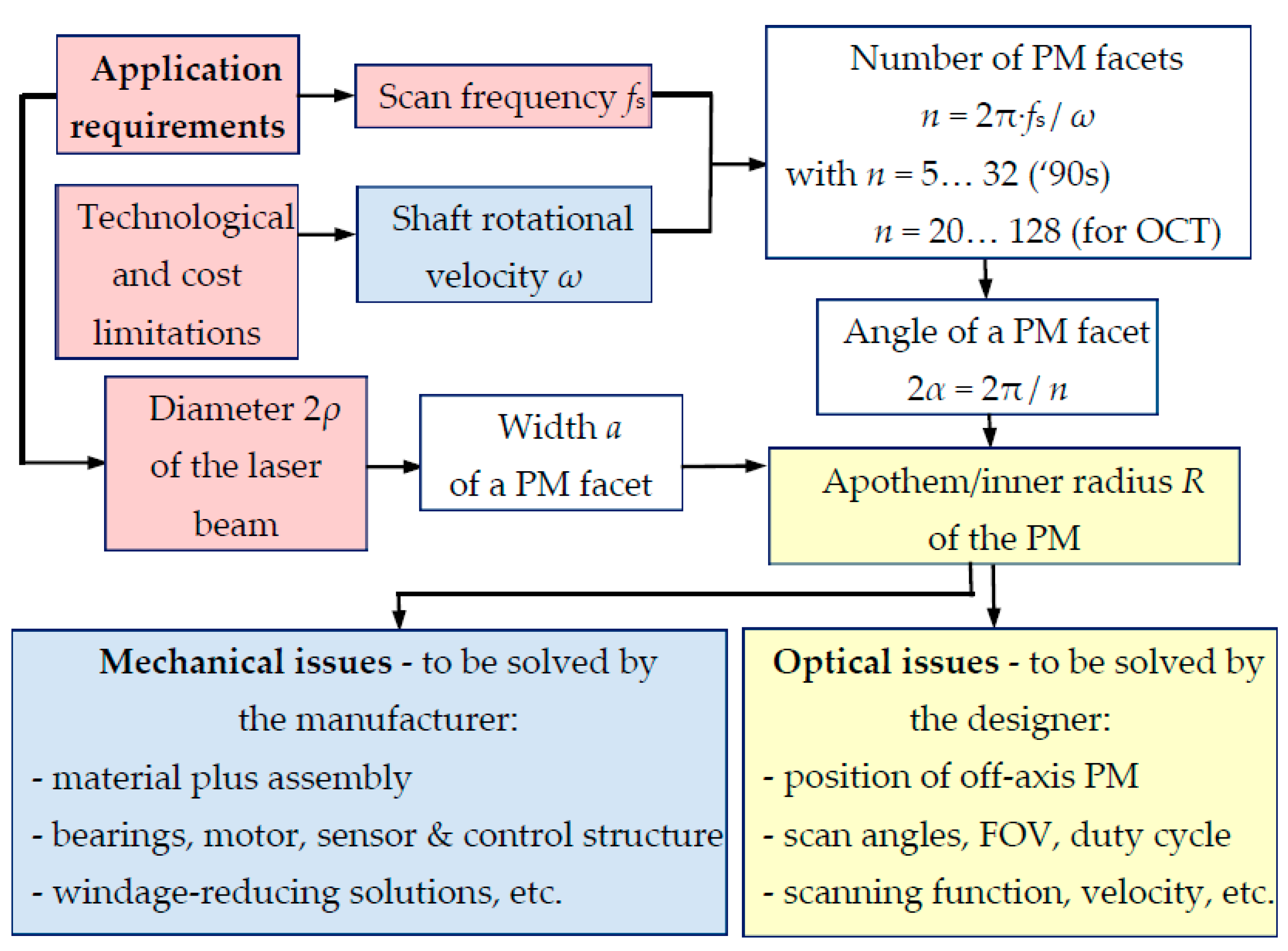
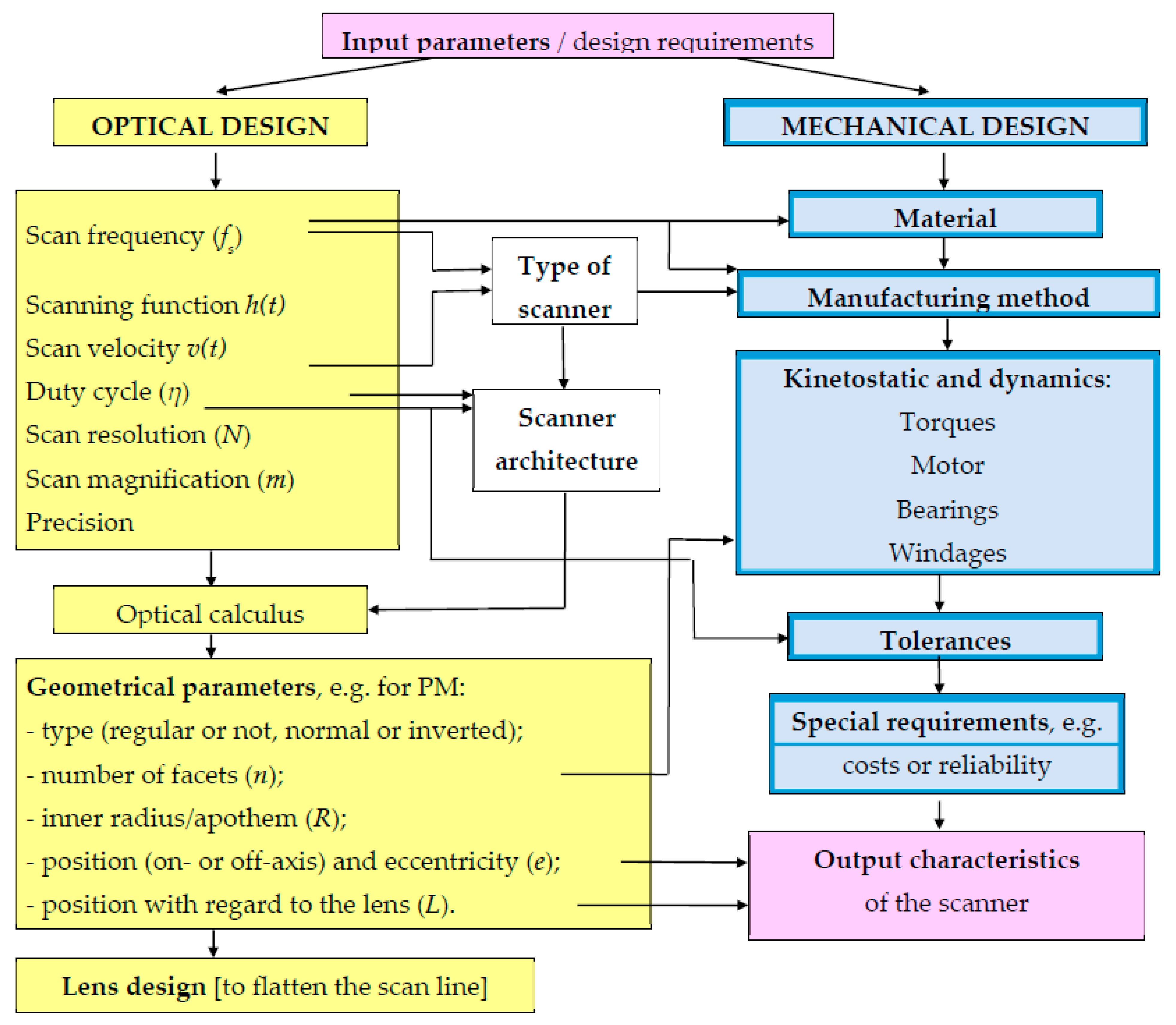
6. Optomechanical Design Scheme
- -
- The scan frequency fs, in connection to the maximum chosen level of the rotational speed ω, imposes, through the FEA, the type of material for the PM.
- -
- -
- From the type of scanner, one can chose the scanner architecture: Pre- or post-objective, with an on- or off-axis PM, telescope- or telescope-less, with different types of lenses (or prisms), with single- or double-pass, etc.
- -
- The previous point, together with the optical parameters calculus, leads to the optical design and then to the geometric parameters of PM, including eccentricity e and distance L—with the functions developed in the present study.
- -
- A lens design (achromatic doublet or F-theta lens) may follow or, alternatively, a solution such as the two-mirrors device proposed in Section 4 to linearize the scanning function even without a lens (or with as low cost as possible).
- -
- The optical calculus is linked to technological tolerances: It imposes them, but it must also consider their levels to calculate (supplemental) functional errors.
- -
- The geometric optical parameters and functions also influence the decisions regarding kinetostatic and dynamic aspects such as torques, calculus of motors, and, related to this, bearings, as well as windage calculus and solutions to decrease it. The type of chosen PM impacts the design with dynamic balance calculus.
- -
- The design can be completed after considering (necessary) thresholds implying cost and reliability.
7. Conclusions
Author Contributions
Funding
Acknowledgments
Conflicts of Interest
Appendix A
Appendix B
References
- Marshall, G.F.; Stutz, G.E. (Eds.) Handbook of Optical and Laser Scanning; CRC Press: London, UK, 2011. [Google Scholar]
- Beiser, L.; Johnson, B. Scanners. In Handbook of Optics, 3rd ed.; Bass, M., Ed.; Mc. Graw-Hill Inc.: New York, NY, USA, 2009; pp. 30.1–30.68. [Google Scholar]
- Benner, W.R. Laser Scanners: Technologies and Applications; Pangolin Laser Systems, Inc.: Sanford, FL, USA, 2016. [Google Scholar]
- Montagu, J. Scanners—Galvanometric and Resonant. In Encyclopedia of Optical and Photonic Engineering, 2nd ed.; Hoffman, C., Driggers, R., Eds.; CRC Press: Boca Raton, FL, USA, 2015. [Google Scholar]
- Aylward, R.P. Advances and technologies of galvanometer-based optical scanners. Proc. SPIE 1999, 3787, 158–164. [Google Scholar] [CrossRef]
- Gadhok, J.S. Achieving high-duty cycle sawtooth scanning with galvanometric scanners. Proc. SPIE 1999, 3787, 173–180. [Google Scholar] [CrossRef]
- Duma, V.-F.; Lee, K.-S.; Meemon, P.; Rolland, J.P. Experimental investigations of the scanning functions of galvanometer-based scanners with applications in OCT. Appl. Opt. 2011, 50, 5735–5749. [Google Scholar] [CrossRef] [PubMed]
- Braaf, B.; Vermeer, K.; Vienola, K.; de Boer, J. Angiography of the retina and the choroid with phase-resolved OCT using interval-optimized backstitched B-scans. Opt. Express 2012, 20, 20516–20534. [Google Scholar] [CrossRef] [PubMed][Green Version]
- Duma, V.-F.; Tankam, P.; Huang, J.; Won, J.; Rolland, J.P. Optimization of galvanometer scanning for optical coherence tomography. Appl. Opt. 2015, 54, 5495–5507. [Google Scholar] [CrossRef] [PubMed]
- Duma, V.-F. Laser scanners with oscillatory elements: Design and optimization of 1D and 2D scanning functions. Appl. Math. Model. 2018, 67, 456–476. [Google Scholar] [CrossRef]
- Yoo, H.W.; Ito, S.; Schitter, G. High speed laser scanning microscopy by iterative learning control of a galvanometer scanner. Control Eng. Pract. 2016, 50, 12–21. [Google Scholar] [CrossRef]
- Hayakawa, T.; Watanabe, T.; Senoo, T.; Ishikawa, M. Gain-compensated sinusoidal scanning of a galvanometer mirror in proportional-integral-differential control using the pre-emphasis technique for motion-blur compensation. Appl. Opt. 2016, 55, 5640–5646. [Google Scholar] [CrossRef]
- Mnerie, C.; Preitl, S.; Duma, V.-F. Galvanometer-Based Scanners: Mathematical Model and Alternative Control Structures for Improved Dynamics and Immunity to Disturbances. Int. J. Struct. Stab. Dyn. 2016, 17, 1740006. [Google Scholar] [CrossRef]
- Walters, C.T. Flat-field postobjective polygon scanner. Appl. Opt. 1995, 34, 2220–2225. [Google Scholar] [CrossRef]
- Sweeney, M.N. Polygon scanners revisited. Proc. SPIE 1997, 3131, 65–76. [Google Scholar] [CrossRef]
- Li, Y.; Katz, J. Asymmetric distribution of the scanned field of a rotating reflective polygon. Appl. Opt. 1997, 36, 342–352. [Google Scholar] [CrossRef]
- Li, Y. Single-mirror beam steering system: Analysis and synthesis of high-order conic-section scan patterns. Appl. Opt. 2008, 47, 386–398. [Google Scholar] [CrossRef] [PubMed]
- Oldenburg, A.L.; Reynolds, J.J.; Marks, D.L.; Boppart, S.A. Fast-Fourier-domain delay line for in vivo optical coherence tomography with a polygonal scanner. Appl. Opt. 2003, 42, 4606–4611. [Google Scholar] [CrossRef] [PubMed]
- Yun, S.H.; Boudoux, C.; Tearney, G.J.; Bouma, B.E. High-speed wavelength-swept semiconductor laser with a polygon-scanner-based wavelength filter. Opt. Lett. 2003, 28, 1981–1983. [Google Scholar] [CrossRef]
- Oh, W.Y.; Yun, S.H.; Tearney, G.J.; Bouma, B.E. 115 kHz tuning repetition rate ultrahigh-speed wavelength-swept semiconductor laser. Opt. Lett. 2005, 30, 3159–3161. [Google Scholar] [CrossRef]
- Mao, Y.; Flueraru, C.; Sherif, S.; Chang, S. High performance wavelength-swept laser with mode-locking technique for optical coherence tomography. Opt. Commun. 2009, 282, 88–92. [Google Scholar] [CrossRef]
- Bräuer, B.; Lippok, N.; Murdoch, S.G.; Vanholsbeeck, F. Simple and versatile long range swept source for optical coherence tomography applications. J. Opt. 2015, 17, 125301. [Google Scholar] [CrossRef]
- Nezam, S.M.R.M. High-speed polygon-scanner-based wavelength-swept laser source in the telescope-less configurations with application in optical coherence tomography. Opt. Lett. 2008, 33, 1741–1743. [Google Scholar] [CrossRef]
- Leung, M.K.K.; Mariampillai, A.; Standish, B.A.; Lee, K.; Munce, N.R.; Vitkin, A.; Yang, V.X.D. High-power wavelength-swept laser in Littman telescope-less polygon filter and dual-amplifier configuration for multichannel optical coherence tomography. Opt. Lett. 2009, 34, 2814–2816. [Google Scholar] [CrossRef]
- Chong, C.; Suzuki, T.; Morosawa, A.; Sakai, T. Spectral narrowing effect by quasi-phase continuous tuning in high-speed wavelength-swept light source. Opt. Express 2008, 16, 21105–21118. [Google Scholar] [CrossRef] [PubMed]
- Everson, M.; Duma, V.-F.; Dobre, G. Geometric & radiometric vignetting associated with a 72-facet, off-axis, polygon mirror for swept source optical coherence tomography (SS-OCT). AIP Conf. Proc. 2017, 1796, 040004. [Google Scholar] [CrossRef]
- Liu, L.; Chen, N.; Sheppard, C.J.R. Double-reflection polygon mirror for high-speed optical coherence microscopy. Opt. Lett. 2007, 32, 3528–3530. [Google Scholar] [CrossRef] [PubMed]
- Duma, V.-F. On-line measurements with optical scanners: Metrological aspects. Proc. SPIE 2005, 5856, 606–618. [Google Scholar] [CrossRef]
- Duma, V.-F. Analysis of polygonal mirror scanning heads: From industrial to high-end applications in swept sources for OCT. Proc. SPIE 2017, 100560, 121–131. [Google Scholar] [CrossRef]
- Duma, V.-F.; Rolland, J.P. Mechanical Constraints and Design Considerations for Polygon Scanners. Mech. Mach. Sci. 2010, 5, 475–483. [Google Scholar] [CrossRef]
- Duma, V.-F.; Podoleanu, A.G. Polygon mirror scanners in biomedical imaging: A review. Proc. SPIE 2013, 8621, 175–183. [Google Scholar] [CrossRef]
- Duma, V.-F. Polygonal mirror laser scanning heads: Characteristic functions. Proc. Rom. Acad. Ser. A 2017, 18, 25–33. [Google Scholar]
- Choi, H.; Park, N.-C.; Kim, W.-C. Minimization of mixed-color image noise caused by shape error of polygonal mirror in color-laser printing system. Microsyst. Technol. 2019, 26, 25–32. [Google Scholar] [CrossRef]
- Sharafutdinova, G.; Holdsworth, J.; Van Helden, D. Improved field scanner incorporating parabolic optics Part 1: Simulation. Appl. Opt. 2009, 48, 4389–4396. [Google Scholar] [CrossRef]
- Hoang, H.-M.; Choi, S.; Park, C.; Choi, J.; Ahn, S.H.; Noh, J. Non-back-reflecting polygon scanner with applications in surface cleaning. Opt. Express 2021, 29, 32939. [Google Scholar] [CrossRef] [PubMed]
- Park, H.-C.; Song, C.; Kang, M.; Jeong, Y.; Jeong, K.-H. Forward imaging OCT endoscopic catheter based on MEMS lens scanning. Opt. Lett. 2012, 37, 2673–2675. [Google Scholar] [CrossRef] [PubMed]
- Warger, W.C., II; DiMarzio, C.A. Dual-wedge scanning confocal reflectance microscope. Opt. Lett. 2007, 32, 2140–2142. [Google Scholar] [CrossRef] [PubMed]
- Bravo-Medina, B.; Strojnik, M.; Garcia-Torales, G.; Torres-Ortega, H.; Estrada-Marmolejo, R.; Beltrán-González, A.; Flores, J.L. Error compensation in a pointing system based on Risley prisms. Appl. Opt. 2017, 56, 2209. [Google Scholar] [CrossRef]
- Li, A.; Yi, W.; Zuo, Q.; Sun, W. Performance characterization of scanning beam steered by tilting double prisms. Opt. Express 2016, 24, 23543. [Google Scholar] [CrossRef]
- Li, A.; Liu, X.; Sun, J.; Lu, Z. Risley-prism-based multi-beam scanning LiDAR for high-resolution three-dimensional imaging. Opt. Lasers Eng. 2021, 150, 106836. [Google Scholar] [CrossRef]
- Li, Y. Third-order theory of the Risley-prism-based beam steering system. Appl. Opt. 2011, 50, 679–686. [Google Scholar] [CrossRef]
- Duma, V.-F.; Dimb, A.-L. Exact Scan Patterns of Rotational Risley Prisms Obtained with a Graphical Method: Multi-Parameter Analysis and Design. Appl. Sci. 2021, 11, 8451. [Google Scholar] [CrossRef]
- Huang, D.; Swanson, E.A.; Lin, C.P.; Schuman, J.S.; Stinson, W.G.; Chang, W.; Hee, M.R.; Flotte, T.; Gregory, K.; Puliafito, C.A.; et al. Optical coherence tomography. Science 1991, 254, 1178–1181. [Google Scholar] [CrossRef]
- Drexler, W.; Liu, M.; Kumar, A.; Kamali, T.; Unterhuber, A.; Leitgeb, R.A. Optical coherence tomography today: Speed, contrast, and multimodality. J. Biomed. Opt. 2014, 19, 071412. [Google Scholar] [CrossRef]
- Podoleanu, A.G.; Rosen, R.B. Combinations of techniques in imaging the retina with high resolution. Prog. Retin. Eye Res. 2008, 27, 464–499. [Google Scholar] [CrossRef] [PubMed]
- Meemon, P.; Yao, J.; Lee, K.-S.; Thompson, K.P.; Ponting, M.; Baer, E.; Rolland, J.P. Optical Coherence Tomography Enabling Non Destructive Metrology of Layered Polymeric GRIN Material. Sci. Rep. 2013, 3, 1709–1710. [Google Scholar] [CrossRef]
- Oever, J.V.; Thompson, D.; Gaastra, F.; Groendijk, H.; Offerhaus, H. Early interferometric detection of rolling contact fatigue induced micro-cracking in railheads. NDT E Int. 2016, 86, 14–19. [Google Scholar] [CrossRef]
- Carrasco-Zevallos, O.M.; Viehland, C.; Keller, B.; McNabb, R.P.; Kuo, A.N.; Izatt, J.A. Constant linear velocity spiral scanning for near video rate 4D OCT ophthalmic and surgical imaging with isotropic transverse sampling. Biomed. Opt. Express 2018, 9, 5052–5070. [Google Scholar] [CrossRef] [PubMed]
- Schneider, H.; Park, K.-J.; Häfer, M.; Rüger, C.; Schmalz, G.; Krause, F.; Schmidt, J.; Ziebolz, D.; Haak, R. Dental Applications of Optical Coherence Tomography (OCT) in Cariology. Appl. Sci. 2017, 7, 472. [Google Scholar] [CrossRef]
- Podoleanu, A.G.; Dobre, G.M.; Cucu, R.G.; Rosen, R.B. Sequential optical coherence tomography and confocal imaging. Opt. Lett. 2004, 29, 364–366. [Google Scholar] [CrossRef]
- Available online: https://www.cambridgetechnology.com/products/polygon-laser-scanner (accessed on 30 January 2022).
- Jung, W.; Kim, J.; Jeon, M.; Chaney, E.J.; Stewart, C.N.; Boppart, S.A. Handheld Optical Coherence Tomography Scanner for Primary Care Diagnostics. IEEE Trans. Biomed. Eng. 2010, 58, 741–744. [Google Scholar] [CrossRef]
- Cogliati, A.; Canavesi, C.; Hayes, A.; Tankam, P.; Duma, V.-F.; Santhanam, A.; Thompson, K.P.; Rolland, J.P. MEMS-based handheld scanning probe for distortion-free images in Gabor-Domain Optical Coherence Microscopy. Opt. Express 2016, 24, 13365–13374. [Google Scholar] [CrossRef]
- Duma, V.-F.; Demian, D.; Sinescu, C.; Cernat, R.; Dobre, G.; Negrutiu, M.L.; Topala, F.I.; Hutiu, G.; Bradu, A.; Podoleanu, A.G. Handheld scanning probes for optical coherence tomography: Developments, applications, and perspectives. Rom. Rep. Phys. 2016, 9670, 96700V. [Google Scholar] [CrossRef]
- Pande, P.; Shelton, R.L.; Monroy, G.L.; Nolan, R.M.; Boppart, S.A. Low-cost hand-held probe for depth-resolved low-coherence interferometry. Biomed. Opt. Express 2016, 8, 338–348. [Google Scholar] [CrossRef]
- Lu, C.D.; Kraus, M.F.; Potsaid, B.; Liu, J.J.; Choi, W.; Jayaraman, V.; Cable, A.E.; Hornegger, J.; Duker, J.S.; Fujimoto, J.G. Handheld ultrahigh speed swept source optical coherence tomography instrument using a MEMS scanning mirror. Biomed. Opt. Express 2013, 5, 293–311. [Google Scholar] [CrossRef] [PubMed]
- Monroy, G.L.; Won, J.; Spillman, D.R.; Dsouza, R.; Boppart, S.A. Clinical translation of handheld optical coherence tomography: Practical considerations and recent advancements. J. Biomed. Opt. 2017, 22, 1–30. [Google Scholar] [CrossRef]
- Available online: https://www.cambridgetechnology.com/products/galvanometer-scanner (accessed on 4 January 2022).
- Available online: https://www.thorlabs.us/navigation.cfm?guide_id=2269 (accessed on 4 January 2022).
- Available online: https://www.scanlab.de/en (accessed on 4 January 2022).
- Bibas, C. Beam Director with Improved Optics. U.S. Patent 10,416,444, 17 September 2019. [Google Scholar]
- Bibas, C. Lens-Free Optical Scanners for Metal Additive Manufacturing. JOM 2022, 74, 1176–1187. [Google Scholar] [CrossRef]
- Mu, X.; Zhou, G.; Yu, H.; Du, Y.; Feng, H.; Tsai, J.M.L.; Chau, F.S. Compact MEMS-driven pyramidal polygon reflector for circumferential scanned endoscopic imaging probe. Opt. Express 2012, 20, 6325–6339. [Google Scholar] [CrossRef] [PubMed]
- Strathman, M.; Liu, Y.; Keeler, E.G.; Song, M.; Baran, U.; Xi, J.; Sun, M.-T.; Wang, R.; Li, X.; Lin, L.Y. MEMS scanning micromirror for optical coherence tomograph. Biomed. Opt. Express 2015, 6, 211. [Google Scholar] [CrossRef] [PubMed]
- Gora, M.J.; Suter, M.J.; Tearney, G.J.; Li, X. Endoscopic optical coherence tomography: Technologies and clinical applications [Invited]. Biomed. Opt. Express 2017, 8, 2405–2444. [Google Scholar] [CrossRef]
- Duma, M.-A.; Duma, V.-F. Two-mirror device for laser scanning systems: Multi-parameter analysis. Proc. SPIE 2017, 10330, 1033014. [Google Scholar]


| Characteristic Function/Parameter | Galvanometer Scanner (GS) | Polygon Mirror (PM) Scanning Head | |||
|---|---|---|---|---|---|
| Scanning function h(θ) | (1) | (4) | |||
| Scanning velocity | (2) | (5) | |||
| Scanning acceleration | (3) | (6) | |||
| Migration functions | - | Transversal | (7) | ||
| Longitudinal/axial | (8) | ||||
| Scan angles, Figure 1a, Figure 2a and Figure 3 | Extreme | π/2 − θm and θm, where | (9) | (12) | |
| Effective | π/2 − θa and θa, where | (10) | θ1 and θ2, , with H < D/2 | (13) | |
| Field of View (FOV) | Angular | (11) | (14) | ||
| Linear/ Scanning domain | (15) | , where x = e/R | (16) | ||
| Duty cycle, Figure 1a,c and Figure 2a | Theoretical (of the input) | (17) | (19) | ||
| Effective (of the output) | (18) | ||||
Publisher’s Note: MDPI stays neutral with regard to jurisdictional claims in published maps and institutional affiliations. |
© 2022 by the authors. Licensee MDPI, Basel, Switzerland. This article is an open access article distributed under the terms and conditions of the Creative Commons Attribution (CC BY) license (https://creativecommons.org/licenses/by/4.0/).
Share and Cite
Duma, V.-F.; Duma, M.-A. Optomechanical Analysis and Design of Polygon Mirror-Based Laser Scanners. Appl. Sci. 2022, 12, 5592. https://doi.org/10.3390/app12115592
Duma V-F, Duma M-A. Optomechanical Analysis and Design of Polygon Mirror-Based Laser Scanners. Applied Sciences. 2022; 12(11):5592. https://doi.org/10.3390/app12115592
Chicago/Turabian StyleDuma, Virgil-Florin, and Maria-Alexandra Duma. 2022. "Optomechanical Analysis and Design of Polygon Mirror-Based Laser Scanners" Applied Sciences 12, no. 11: 5592. https://doi.org/10.3390/app12115592
APA StyleDuma, V.-F., & Duma, M.-A. (2022). Optomechanical Analysis and Design of Polygon Mirror-Based Laser Scanners. Applied Sciences, 12(11), 5592. https://doi.org/10.3390/app12115592