
Time Domain Damage Identification Approach of the Newly Hollow Floor Structure with TRMD


Abstract
:1. Introduction
2. Theoretical Formulation
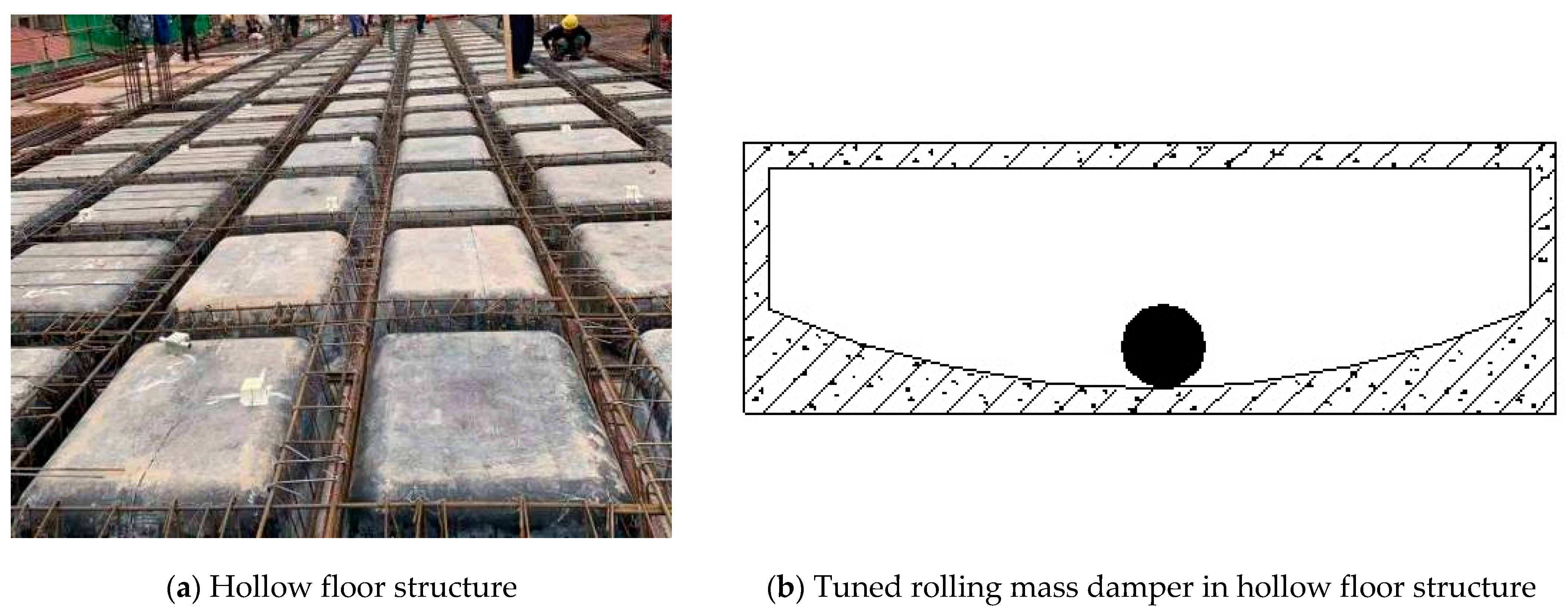
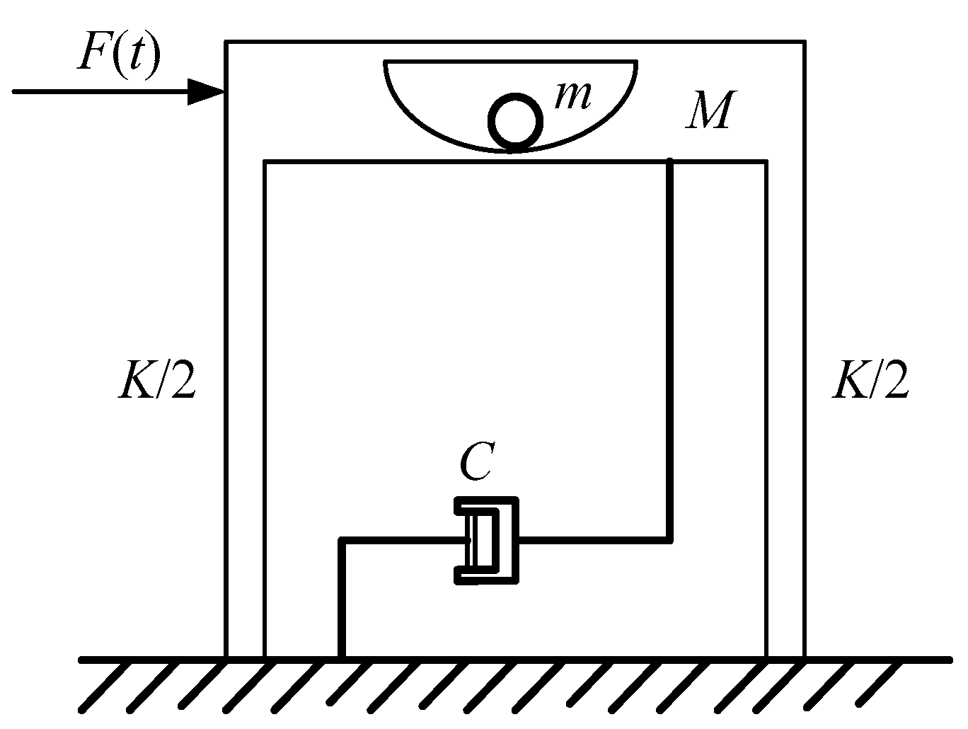
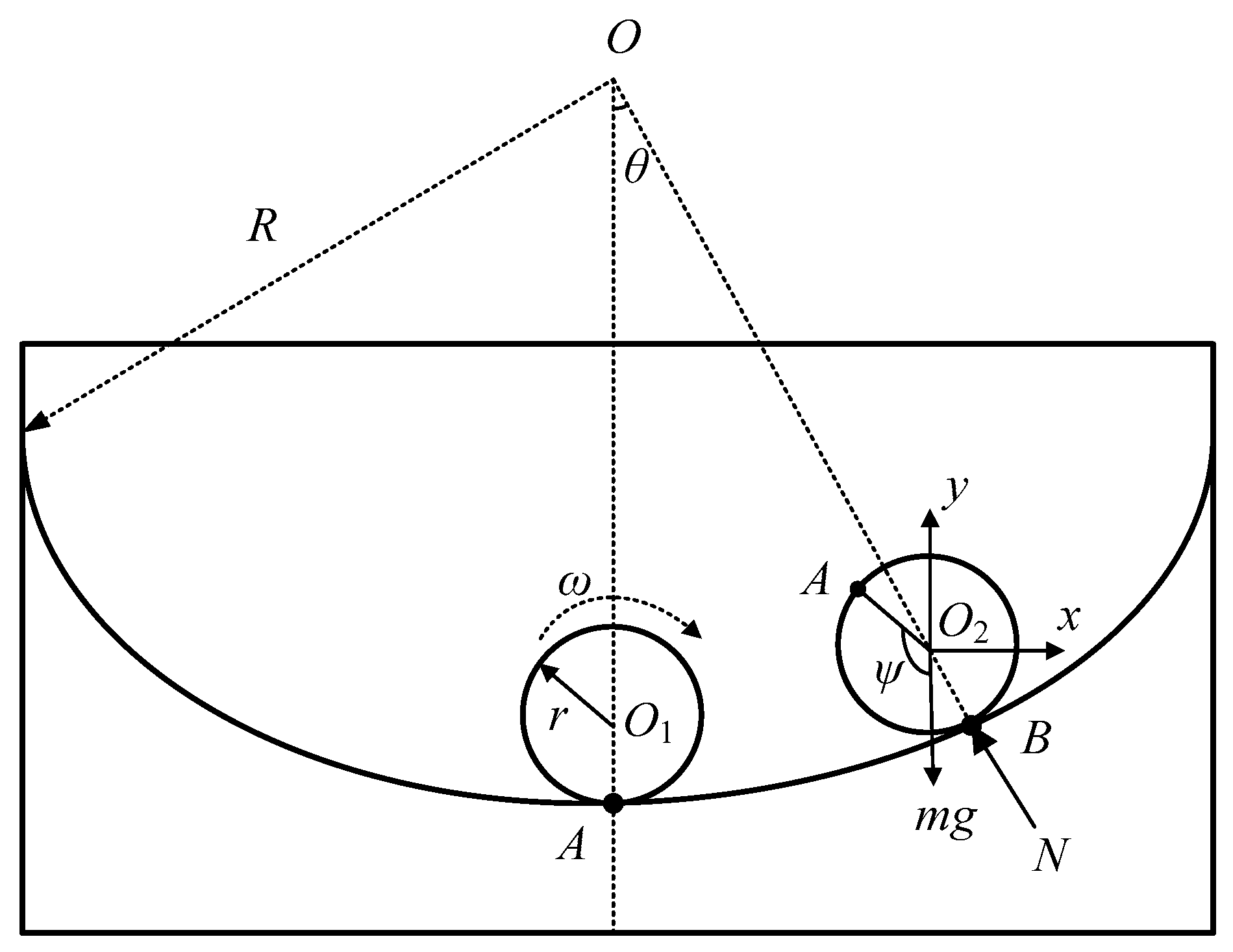
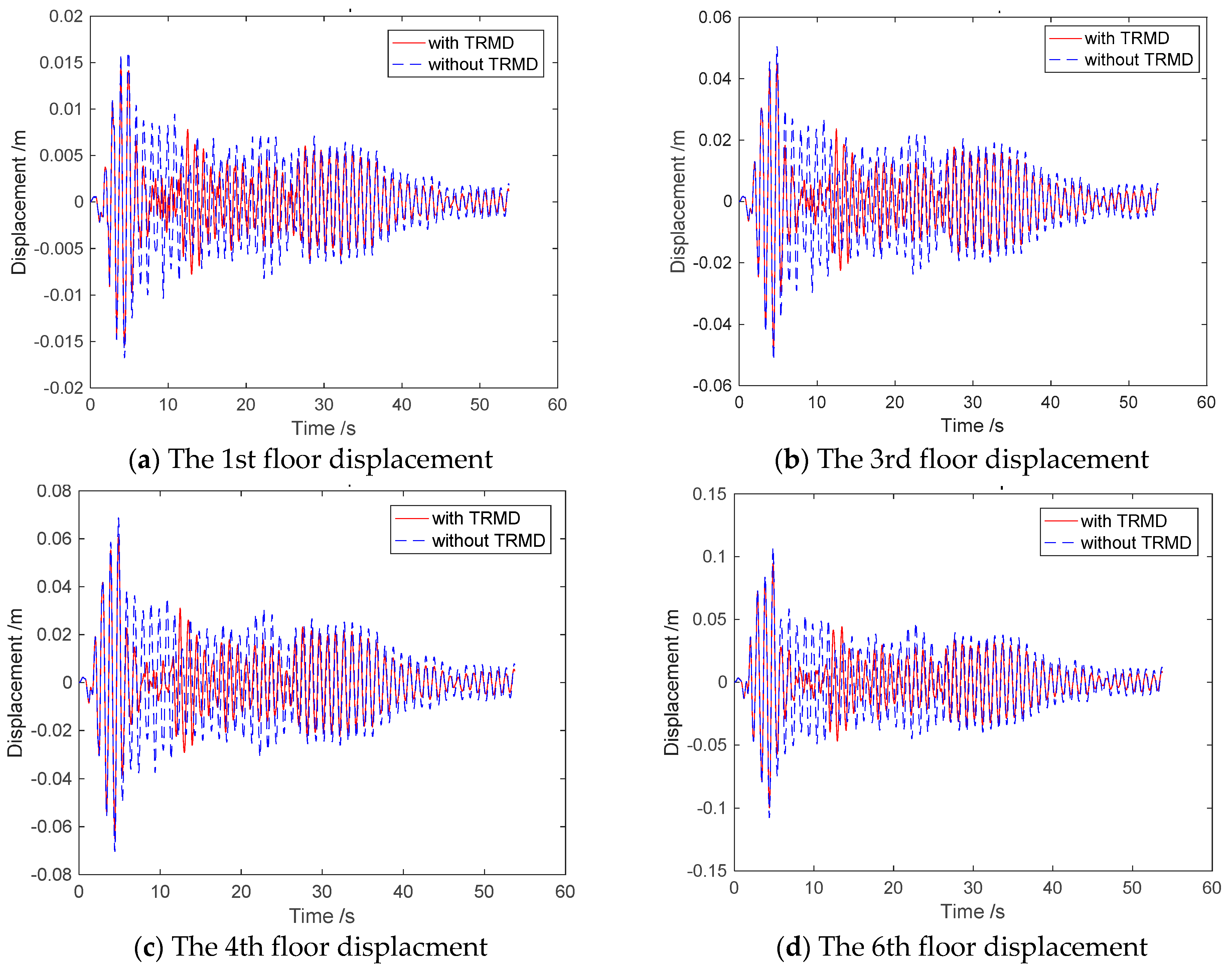
2.1. Simplified Model and Motion Equation of a Controlled Structure with TRMD
2.2. Motion Equation for an MDOF Structure with TRMD
2.3. Dynamic Response Sensitivity Analysis
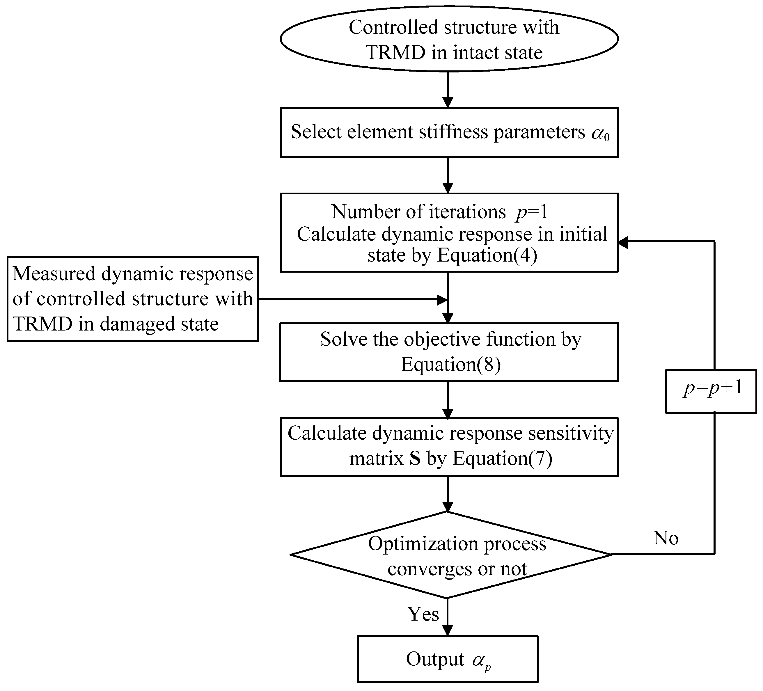
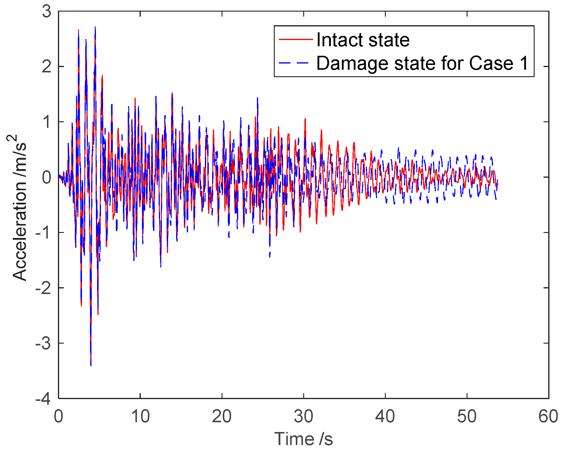
2.4. Sensitivity-Based Damage Identification
3. Numerical Example
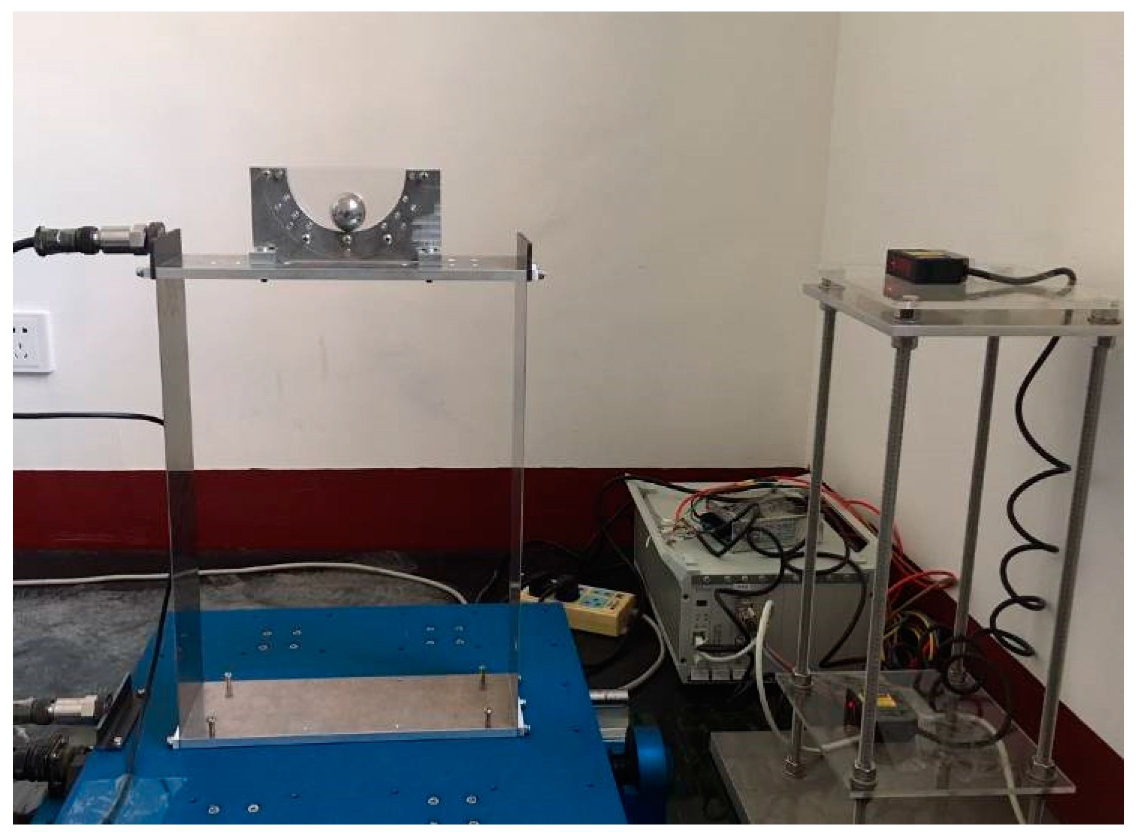
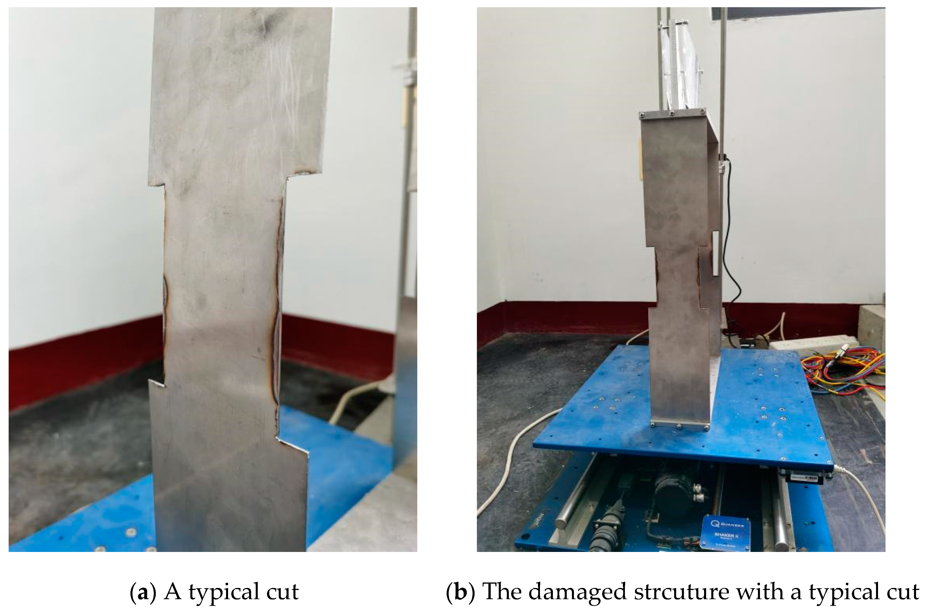
4. Experimental Validation
5. Conclusions
Author Contributions
Funding
Institutional Review Board Statement
Informed Consent Statement
Data Availability Statement
Conflicts of Interest
References
- Khouzani, M.A.; Zeynalian, M.; Hashemi, M.; Mostofinejad, D.; Farahbod, F. Study on shear behavior and capacity of biaxial ellipsoidal voided slabs. Structures 2020, 27, 1075–1085. [Google Scholar] [CrossRef]
- Sagadevan, R.; Rao, B.N. Flexural Behavior of Reinforced Concrete Biaxial Voided Square Slabs. ACI Struct. J. 2020, 117, 3–14. [Google Scholar]
- Yao, J.T.P. Concept of Structural Control. J. Struct. Eng.-ASCE 1972, 98, 1567–1574. [Google Scholar] [CrossRef]
- Zhang, M.; Xu, F. Tuned mass damper for self-excited vibration control: Optimization involving nonlinear aeroelastic effect. J. Wind Eng. Ind. Aerodyn. 2022, 220, 104836. [Google Scholar] [CrossRef]
- Jahangiri, V.; Sun, C.; Kong, F. Study on a 3D pounding pendulum TMD for mitigating bi-directional vibration of offshore wind turbines. Eng. Struct. 2021, 241, 112383. [Google Scholar] [CrossRef]
- Xie, S.; Jin, X.; He, J.; Gao, J.; Zhang, C.; Yan, Y. Applying multiple tuned mass dampers to control structural loads of bottom-fixed offshore wind turbines with inclusion of soil-structure interaction. Ocean Eng. 2020, 205, 107289. [Google Scholar] [CrossRef]
- Pirner, M. Actual behaviour of a ball vibration absorber. J. Wind Eng. Ind. Aerodyn. 2002, 90, 987–1005. [Google Scholar] [CrossRef]
- Obata, M.; Shimazaki, Y. Optimum Parametric Studies on Tuned Rotary-Mass Damper. J. Vib. Control 2008, 14, 867–884. [Google Scholar] [CrossRef]
- Obata, M.; Shimazaki, Y. Vibration control effects and application example of tuned rotary damped mass damper. Struct. Eng. 2007, 85, 41–45. [Google Scholar]
- Li, S.; Fu, L.; Kong, F. Seismic response reduction of structures equipped with a voided biaxial slab-based tuned rolling mass damper. Shock Vib. 2015, 2015, 760394. [Google Scholar] [CrossRef] [Green Version]
- Li, S.; Sun, L.; Kong, F. Vibration Control Performance Analysis and Shake-Table Test of a Pounding Tuned Rotary Mass Damper under the Earthquake. Shock Vib. 2019, 2019, 4038657. [Google Scholar] [CrossRef] [Green Version]
- Kwok, K.C.S.; Samali, B. Performance of tuned mass dampers under wind loads. Eng. Struct. 1995, 17, 655–667. [Google Scholar] [CrossRef]
- Yang, J.Y.; Xia, B.H.; Chen, Z.S. Vibration-Based Structural Damage Identification: A Review. Int. J. Robot. Autom. 2020, 35, 123–131. [Google Scholar] [CrossRef]
- Hou, R.R.; Xia, Y.; Zhou, X.Q. Structural damage detection based on l(1) regularization using natural frequencies and mode shapes. Struct. Control Health Monit. 2018, 25, e2107. [Google Scholar] [CrossRef]
- Koushik, R. Structural damage identification using mode shape slope and curvature. J. Eng. Mech. 2017, 143, 04017110. [Google Scholar] [CrossRef]
- Huang, Q.; Xu, Y.; Li, J.; Su, Z.; Liu, H. Structural damage detection of controlled building structures using frequency response functions. J. Sound Vib. 2012, 331, 3476–3492. [Google Scholar] [CrossRef]
- Lu, Y.; Gao, F. A novel time-domain auto-regressive model for structural damage diagnosis. J. Sound Vib. 2005, 283, 1031–1049. [Google Scholar] [CrossRef]
- Lu, Z.R.; Liu, J.K.; Huang, M.; Xu, W.H. Identification of local damages in coupled beam systems from measured dynamic responses. J. Sound Vib. 2009, 326, 177–189. [Google Scholar] [CrossRef]
- Zhu, H.-P.; Mao, L.; Weng, S. A sensitivity-based structural damage identification method with unknown input excitation using transmissibility concept. J. Sound Vib. 2014, 333, 7135–7150. [Google Scholar] [CrossRef]
- Zhu, H.; Mao, L.; Weng, S.; Xia, Y. Structural damage and force identification under moving load. Struct. Eng. Mech. 2015, 53, 261–276. [Google Scholar] [CrossRef]
- Singh, M.P.; Singh, S.; Moreschi, L.M. Tuned mass dampers for response control of torsional buildings. Earthq. Eng. Struct. Dyn. 2002, 31, 749–769. [Google Scholar] [CrossRef]
- Brownjohn, J.M.W.; Xia, P.Q.; Hao, H.; Xia, Y. Civil structure condition assessment by FE model updating: Methodology and mentcase studies. Finite Elem. Anal. Des. 2001, 37, 761–775. [Google Scholar] [CrossRef]


| Damage Location | Damage Severity | Noise Severity | |
|---|---|---|---|
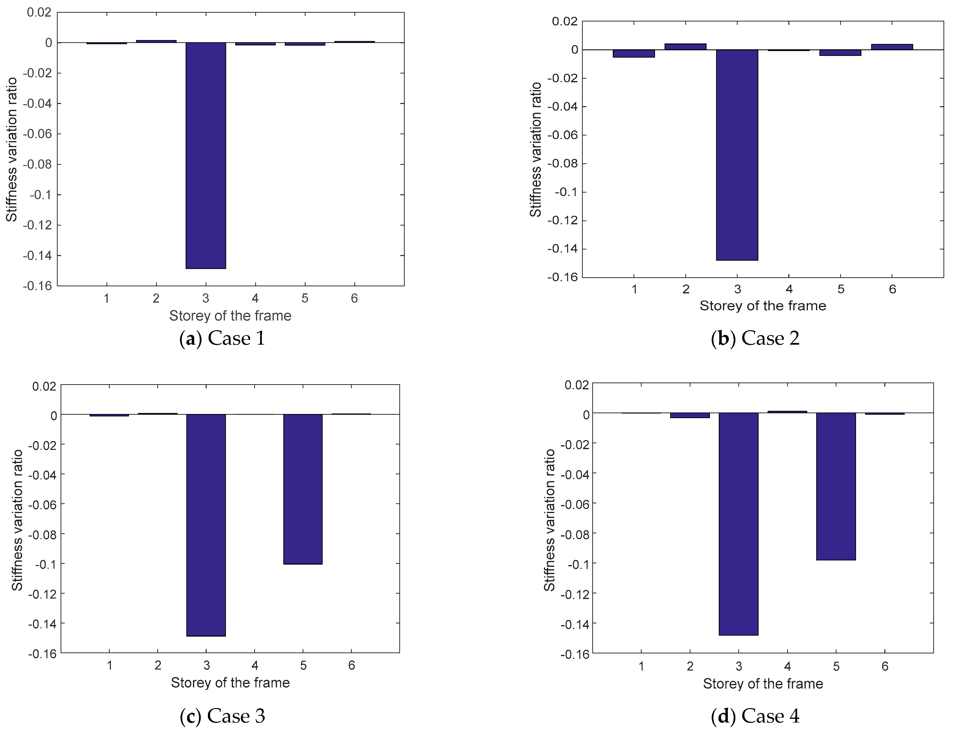
| Case 1 | 3rd floor | 15% | No noise |
| Case 2 | 3rd floor | 15% | 5% noise |
| Case 3 | 3rd floor, 5th floor | 15%, 10% | No noise |
| Case 4 | 3rd floor, 5th floor | 15%, 10% | 5% noise |
| Storey Stiffness | Intact State | Case 1 | Case 2 | Case 3 | Case 4 | ||||
|---|---|---|---|---|---|---|---|---|---|
| Stiffness | Stiffness | Stiffness Variation Ratio | Stiffness | Stiffness Variation Ratio | Stiffness | Stiffness Variation Ratio | Stiffness | Stiffness Variation Ratio | |
| (N/m) | (N/m) | (N/m) | (N/m) | (N/m) | |||||
| k1 | 13,510,000 | 13,502,578 | −0.05% | 13,442,643 | −0.50% | 13,499,127 | −0.08% | 13,512,298 | 0.02% |
| k2 | 12,860,000 | 12,889,338 | 0.23% | 12,922,290 | 0.48% | 12,877,745 | 0.14% | 12,827,860 | −0.25% |
| k3 | 11,580,000 | 9,861,830 | −14.84% | 9,870,298 | −14.76% | 9,859,303 | −14.86% | 9866889 | −14.79% |
| k4 | 9,650,000 | 9,637,782 | −0.13% | 9,646,141 | −0.04% | 9,651,837 | 0.02% | 9,662,867 | 0.13% |
| k5 | 7,070,000 | 7,065,124 | −0.07% | 7,048,940 | −0.30% | 6,367,359 | −9.94% | 6384208 | −9.70% |
| k6 | 3,860,000 | 3,864,854 | 0.13% | 3,876,070 | 0.42% | 3,862,899 | 0.08% | 3,857,500 | −0.06% |
| Size of Stainless Steel Sheet/mm | Mass of Stainless Steel Sheet/g | Size of Aluminum Alloy Plate/mm | Mass of Aluminum Alloy Plate/g | Natural Frequency/Hz | Damping Ratio |
|---|---|---|---|---|---|
| 500 × 100 × 1 | 333 (single sheet) | 300 × 100 × 10 | 797 | 1.465 | 0.057 |
| Arched Path Radius R/mm | Radius of the Ball r/mm | Mass of the Ball/g |
|---|---|---|
| 110 | 11 | 50 |
| Case 1 | Case 2 | Case 3 | |
|---|---|---|---|
| Configuration | Uncontrolled | Controlled with TRMD | Controlled with TRMD |
| Intact | Intact | d = 15 mm b = 100 mm |
Publisher’s Note: MDPI stays neutral with regard to jurisdictional claims in published maps and institutional affiliations. |
© 2022 by the authors. Licensee MDPI, Basel, Switzerland. This article is an open access article distributed under the terms and conditions of the Creative Commons Attribution (CC BY) license (https://creativecommons.org/licenses/by/4.0/).
Share and Cite
Mao, L.; Li, S.; Yin, Y.; Zhang, Z. Time Domain Damage Identification Approach of the Newly Hollow Floor Structure with TRMD. Appl. Sci. 2022, 12, 5647. https://doi.org/10.3390/app12115647
Mao L, Li S, Yin Y, Zhang Z. Time Domain Damage Identification Approach of the Newly Hollow Floor Structure with TRMD. Applied Sciences. 2022; 12(11):5647. https://doi.org/10.3390/app12115647
Chicago/Turabian StyleMao, Ling, Shujin Li, Yayun Yin, and Zhou Zhang. 2022. "Time Domain Damage Identification Approach of the Newly Hollow Floor Structure with TRMD" Applied Sciences 12, no. 11: 5647. https://doi.org/10.3390/app12115647