1. Introduction
The interest in industrial areas was born in England in 1950 in many different cultural circles, where growing attention was paid to the industrial revolution evidence. England was one of the most involved nations in technological, social, and cultural changes caused by the Industrial Revolutions to have a major role in the protection of the industrial heritage. From the end of the 19th century to the beginning of the 20th one, intellectual movements, the so-called trusts, appeared. They made, for the first time, the request of the preservation of industrial sites and buildings, trying to raise public awareness on these issues. After World War II, the reconstruction of destroyed cities brought the demolition of many disused industrial buildings and sites. This caused the opposition of the citizens, who began to see historical and social value in that kind of heritage. In the late 1960s, the Ironbridge Gorge Museum Trust was born. It was the first institute for the protection of the industrial heritage in Ironbridge, where one of the first iron production plants and a famous and peculiar cast-iron bridge were located. This association aimed to sensitize people through research, academic, and educational activities.
In Italy, the interest in the industrial areas dated back to 1970, when industry begins to be considered as identity and memory of the population. In the second half of the 1970s, many researchers began to study the industrial heritage and to introduce the concept of “industrial archaeology”. This term was defined for the first time in 1977 on the “Bulletin of the Documentation Center for the Industrial Archaeology”, founded in Milan by Eugenio Battisti [
1,
2]. In 1980, the productive activities take cultural value and were recognized as national heritage. One of the most important rehabilitation interventions of a disused factory dated back to 1982, when the Royal Bourbonic Factory, founded in Naples in 1840, was recovered and turned into the new National Railway Museum. In addition, the return of disused industrial areas to the cities was considered as a good opportunity to re-design the urban tissue. In the 1990s, industrial constructions became cultural and historical goods producing richness, both in terms of economy and protection of historical, cultural, and landscape identity of cities and communities [
3]. In 1997, the Italian Association for the Industrial Archaeological Heritage (AIPAI) was born with the aim of analyzing, cataloguing, preserving, and valuing the industrial heritage and its connections with cultural and natural goods.
The interest in industrial areas was also justified by the necessity to recover these often-abandoned sites through appropriate structural and seismic interventions. Recent earthquakes, including that which occurred in 2012 in the Emilia-Romagna region of Italy, showed the weakness of new industrial buildings, which collapsed or exhibited serious damages. For this purpose, the cataloguing of the different industrial buildings located in the Italian territory was carried out by the Italian Consortium ReLUIS “Network of Seismic Engineering University Laboratories”. This university consortium elaborated the so-called “Cartis Long Spans” form to create a map of typological classes of buildings aiming at giving precise indications on the seismic vulnerability of this built heritage. Ancient interventions on these buildings were mainly based on steelwork [
4], but, more recently, some other materials and techniques replaced the use of steel systems, whose design methods were incorporated into manuals and standard codes [
5,
6]. Nevertheless, in the cases when it is mandatory to make interventions only outside the building, so avoiding interrupting its use, applications with steel exoskeletons [
7,
8,
9,
10] represent one of the best choices for a global requalification of constructions from architectural, structural, and environmental viewpoints [
11,
12,
13].
Starting from these premises, in the current paper, the seismic analysis and the combined seismic–energy retrofit of a former reinforced concrete tobacco factory in Cervinara, within the district of Avellino (Italy), were carried out. The investigated industrial building was placed into a disused industrial area containing six RC constructions erected at the end of the 1960s. This work proposes a seismic retrofit intervention of the examined structure based on the use of steel exoskeletons. FEM models of the building before and after seismic interventions was set up by means of the SAP2000 software, which allowed to perform static nonlinear analyses. Subsequently, a photovoltaic plant using high-efficiency panels was proposed to provide the entire hub’s energy requirement. The integrated use of anti-seismic and energy solutions permitted to refurbish the inspected industrial building.
2. Materials and Methods
2.1. Description of the Case Study
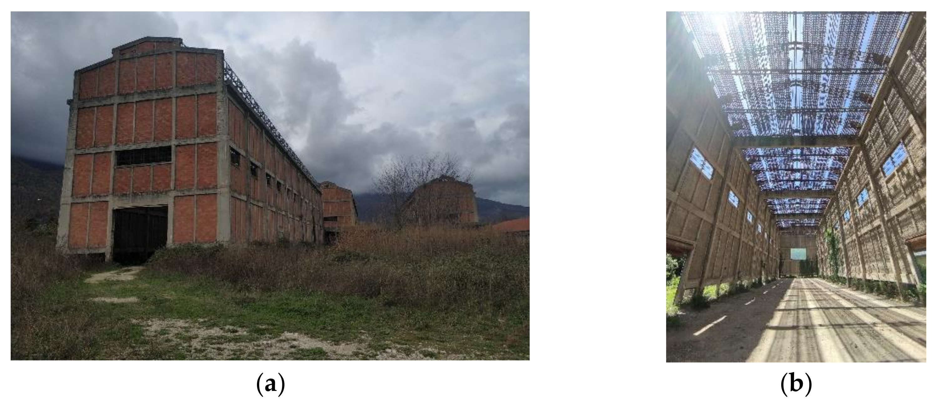
The building under investigation is one of the six RC constructions of the area, probably erected at the end of the 1960s. The building has a plan with a 14.5 × 72.8 m rectangular shape configuration and is developed on a single story with height of 18 m. The building is made up of unidirectional RC frames, connected by cross beams at the top, where a steel trussed roof is placed. All the structural elements have rectangular section, except the edge beams at the top, characterized by a T-shape. The building is covered by infesting plants and it is in an advanced state of decay, even though structural elements do not have important lesions. Pictures of the current building are shown in
Figure 1, while in
Figure 2 there is a metrical survey of the construction.
2.2. Characterization of Materials and Soil
As mentioned above, all the structural elements are made of reinforced concrete and all the frames are filled with hollow brick walls. Since it was not possible to perform destructive and non-destructive tests on building materials, the mechanical characterization of materials is carried out thanks to several studies about evolution of mechanical properties of materials over the years and with in situ tests and visual inspections. All these studies are based on the Italian standards in force at that time [
14]. Therefore, many experimental test values detected from literature sources on existing RC buildings analogous to the building under study are considered. This means that the mechanical properties found automatically consider the decrease of strength and Young’s moduli deriving from environmental actions and loading history applied. Therefore, the range of values suggested from the literature sources is considered and, aiming at performing analysis on the safe side, it was decided to use the lowest value of this range.
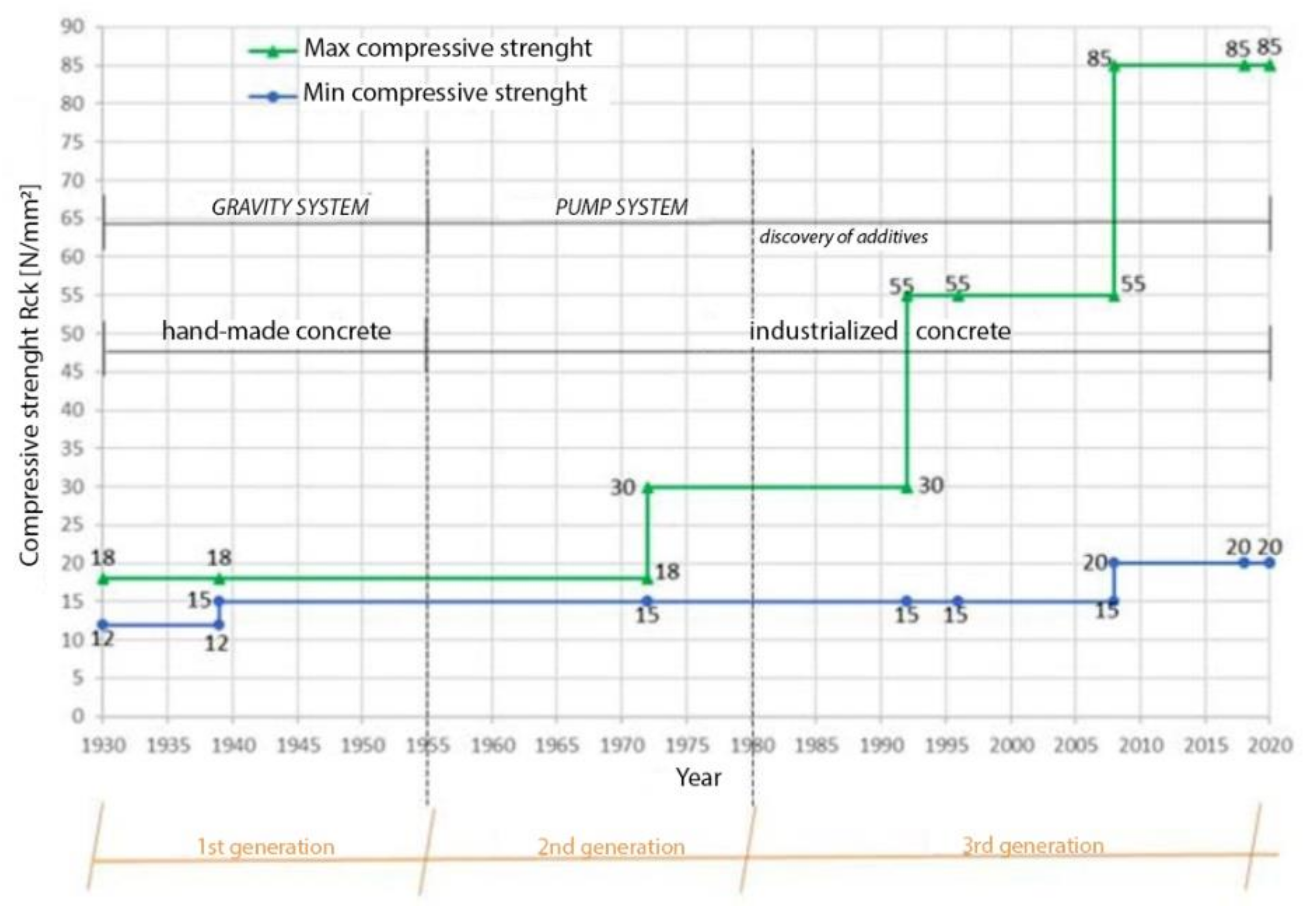
Regarding concrete, according to a literature study [
15], it is possible to define three generations of materials based on the production age:
First generation: from 1930 to 1955;
Second generation: from 1955 to 1980;
Third generation: from 1980 to today.
The industrial building under investigation belongs to the second generation, so the minimum resistance considered is C12/15, as shown in
Figure 3.
The mechanical properties of reinforcement steel are defined with the “STIL v1.0” software, which was defined based on extensive research in the field [
16,
17,
18]. By entering information about production age and steel bars type, the software indicates the average values of yield strength f
y, hardening ratio f
u/f
y, and elongation at failure.
In this case, the considered average value of yield strength is 350 MPa. Visive inspection of degraded elements has allowed to assume the disposition of bars.
With regard to mechanical characterization of the steel trussed roof, a previous study indicated that steel used in 1960 has properties comparable with S235 steel [
19].
According to the Italian standards [
20,
21], the knowledge level of the structure is represented by a confidence factor that reduces the values of the mechanical parameters of the materials. In this case, the confidence factor FC is equal to 1.2, which is the value representative of an intermediate knowledge level.
Regarding subsoil, surveys carried out by the city of Cervinara during the drafting of the 2018 Municipal Urbanistic Plan PUC provided a seismic category B with a topographic category T1, which means a ground slope between 0° and 15°.
2.3. Evaluation of Gravity Loads
The considered building has no intermediate floors and no roof structure, so the only gravity loads are those deriving from both the vertical framed structures and the walls.
Beams, columns, and walls weights are to be calculated according to Italian Code NTC 2018, considering concrete specific weight γRC equal to 25.0 kN∙m−3 and hollow brick specific weight γwall equal to 8.0 kN∙m−3. In particular, the SAP2000 software allows to calculate beams and columns weights automatically, while the infill walls weight Ginfill is considered as distributed load on the beams with a value of 915.78 kN·m−1.
The presence of openings is considered as percentage decrease of walls weight: 10% for the first floor, 20% for the second floor, and 0% for the other floors.
2.4. FEM Modeling and Nonlinear Analysis
The FEM model of the building before intervention (
Figure 4) was set up by means of the SAP2000 v20.0 software according to the Italian Code NTC 2018. Beams and columns are defined as one-dimensional elements by entering all the acquired data about materials and geometries of sections. Interaction between soil and building is schematized by assigning full constraints at the bases of columns. The roof structure is schematized with linear elements able to represent a constraint between east and west facades. Beam-column nodes are considered as rigid with their own stiffness. Infill walls are schematized as distributed loads on the frame members, neglecting their contribution in terms of stiffness. This assumption is justified since the spans are filled with weak cladding walls having thickness of 10 cm only, which are also provided with some openings. Therefore, the contribution given by infill walls to the building lateral stiffness is neglected. In the nonlinear analyses, concentrated plastic hinges are assigned to all the structural members.
The seismic vulnerability evaluation of the building is carried out using N2 method [
22,
23]. This method is based on distribution of horizontal forces acting along the main building directions x and y, parallel to the long and short facades of the building, respectively.
For each direction, two distributions of forces are considered:
- 4.
Horizontal forces equivalent to a uniform distribution of horizontal accelerations, that are proportional to the building seismic mass, and are herein called Accel_x and Accel_y.
- 5.
Horizontal forces proportional to the elastic modal strain of the main vibration mode, and , that are herein called Modal_x and Modal_y.
The evaluation of dynamic properties of the building is carried out through a modal analysis on the structural model. The analysis results of the structure in terms of the force–displacement curves obtained from the SAP2000 software are represented in
Figure 5.
Ductile failure and brittle failure are represented on the curves of
Figure 6 with cyan and red points, respectively.
By representing the capacity curves on the ADRS plane and by comparing them to the elastic response spectrum of the soil, it is possible to obtain the required displacements (
Figure 6). The ratio between capacity displacement and demand one is the safety index (IR), whose values referring to the two analysis directions and seismic force distributions are depicted in
Table 1. In this table du,d* and du,b* are the ductile (bending moment) capacity displacement and the brittle (shear) capacity one, respectively, dr* is the demand displacement required by the earthquake, and IR,d and IR,b are the safety indices related to the ductile failure and the brittle failure, respectively. As it is observed in
Table 1, safety index related to Modal_y case is less than 1, so that the most critical situation is identified precisely along this direction.
2.5. Design of Exoskeletons
To improve the seismic behavior of the factory, both orthogonal and parallel exoskeletons are designed and placed along the building transverse direction (y-direction). From the elastic response spectrum, a target displacement is defined, so that the retrofitted structure remains in the elastic field. In particular, ≤ , being the yielding displacement of the structure.
To evaluate the global lateral stiffness of the retrofitted structure K
d, the following equation is used:
where m* is the mass of the structure and S
ADRS is the elastic spectral acceleration for the displacement
. The formulation above is valid under the hypothesis that the equivalent mass and the modal participation factor of the existing construction and the retrofitted ones remain the same. Furthermore, it is valid under the hypothesis that the yielding displacement of the exoskeleton corresponds to the yielding displacement of the existing structure. Under the hypothesis of parallel coupling, the global lateral stiffness of the exoskeleton Ke can be evaluated by the following equation:
where K
EX is the global lateral stiffness of the existing structure, that can be evaluated as
where
and
are yielding force and displacement of the system, respectively [
24,
25,
26,
27].
With regard to the typological choice, based on the seismic-resistant scheme, and the dimensional choice, related to the first attempt for system design, concentric bracing frames (CBS) and circular hollow sections (CHS) are chosen to comply with the previous provisions related to global lateral stiffness. Columns have diameter of 193.7 mm with thickness from 5 to 10 mm on the longest sides (north and south) and of 219.1 mm with thickness from 8 to 16 mm on the shortest sides (east and west). CHS profiles of 168.3 × 8 mm are used for beams. Bracings along the east and west sides are made of CHS sections with diameter of 114.3 mm and thickness ranging from 3.2 to 8 mm. Instead, bracings of the exoskeletons placed on the building north and south sides have diameter of either 88.9 mm (thickness of 3.2 mm) or 101.6 mm (thickness from 3.2 to 6.3 mm).
In
Figure 7, the disposition of exoskeleton is shown. The orthogonal exoskeletons are connected to horizontal St. Andrew’s cross bracings at every floor.
2.6. Photovoltaic Plant
The huge area and the southern exposure of the roof were used to install a photovoltaic plant with high-efficiency panels. According to the Italian Standard [
28], the minimum power of the plant is calculated through the following equation:
where
S is the building area and
K is an index equal to
.
In this case, all the six buildings of the area, whose dimensions are shown in
Table 2, are considered. The analysis results are shown in
Table 3.
The chosen panel is the Sunpower Maxeon 3, illustrated in
Figure 8. The main features of this panel are reported in
Table 4.
Subsequently, to calculate the annual energetic production of the panel, the PVGIS (Photovoltaic Geographical Information System) software is used. PVGIS is a simulator offered by The European Commission’s Science and Knowledge Service, and, by entering some data, such as panel features, its inclination and orientation, and the place coordinates, it gives back the monthly average of energy efficiency (kWh), the monthly average of irradiation per square meter, and the annual production of the system.
By considering an angle of inclination equal to 11° and a percentage of system losses equal to 14%, the simulator provided the output data shown in
Figure 9.
3. Results
3.1. Seismic Retrofitting
As in the previous case, FEM model of the building after intervention was set up by means of the SAP2000 v20.0 software. Beams, columns, and diagonals of exoskeletons are modeled using one-dimensional elements by entering all the acquired data on both materials and geometries of sections. In this case, interaction between soil and building is schematized by assigning pinned restraints at the bases of columns. The performed nonlinear static analyses give the capacity curves shown in
Figure 10.
By representing the capacity curves in the ADRS plane and by comparing them to the elastic response spectrum of the soil, it is possible to see, as shown in
Figure 11, that the seismic retrofitting and, therefore, new safety indices, are attained only in y-direction (
Table 5).
As shown, exoskeletons brought a significant increase of the safety indices, which attained values greater than 1, so that a marked improvement of the seismic behavior of the building is noticed. Exoskeletons allow to reach an increase of seismic safety of about 30% along the considered directions, by acting only on the building lateral stiffness. This is a satisfactory result that testifies the validity of this intervention.
3.2. Photovoltaic Plant Efficiency
By considering the previous data, it is possible to calculate the annual production of photovoltaic plant per square meter (
Table 6).
These values are compared to the estimated annual energy consumption of several building types and to the benchmark and target data related to schools and offices to assume a hypothetic consumption for the building under investigation, as well as to understand if the plant can provide the entire building’s energy requirement.
From the analysis carried out, it appears that the range of indices is very wide, being framed within a minimum value equal to 60 kWh/m
2 and a maximum value equal to 170 kWh/m
2 [
29]. This means that the percentage of energy requirement of the studied construction may vary between 20% and 60% of that of school and office buildings. Therefore, in the current case, the photovoltaic plant could satisfy the entire energy requirement.
4. Conclusions
In this paper, the seismic and energy rehabilitation of an abandoned RC tobacco factory in Cervinara, in the district of Avellino (Italy), is proposed by designing steel exoskeletons and by installing a photovoltaic plant on the roofs of the building. In situ tests and visual inspections allowed to understand all of the geometrical and mechanical features of the building structural elements used to obtain a FEM model through the SAP2000 software, which allowed to carry out pushover analysis on the building. While the factory showed a good performance in the longitudinal (x) direction with satisfactory safety indices, in the transverse (y) direction, the absence of an appropriate number of seismic-resistant frames reduced the seismic performances, with safety indices less than one. The detected seismic deficiencies led to the design of the optimal seismic intervention to reach an improvement of the seismic features. Steel exoskeletons allowed to improve the global behavior of the building, without neglecting architectural quality, sustainability, and environmental issues. In the weakest building direction (Y-direction), these systems allowed to reach increases in terms of strength and displacements, in order to satisfy the required seismic demand, to attain the complete seismic retrofitting of the structure. In particular, exoskeletons allowed to reach an increase of seismic safety of about 30% by acting only on the building lateral stiffness. Therefore, the significant increase of the safety indices, with values greater than one, decidedly improved the seismic behavior of the building. This satisfactory result testified the validity of this intervention from a seismic viewpoint.
On the other hand, from an energy viewpoint, a photovoltaic plant was designed using high-efficiency panels installed on the wide roof area. The annual production of photovoltaic plant per square meter was compared that of schools and offices, variable in the range from 60 kWh/m2 to 170 kWh/m2, to understand if the plant can provide the entire building’s energy requirement. The performed analyses showed that the energy consumed by the retrofitted building is between 20% and 60% lower than that of school and office buildings. This means that, using these new energy generation systems, the photovoltaic plant allowed to generate an amount of energy able to satisfy the entire building requirements.
As a conclusion, the proposed study showed the validity of exoskeletons as efficient systems to improve both seismic features of RC buildings and values of Italian industrial heritage, which should be preserved and restored since they represent irreplaceable testaments to the industrial archaeology widespread on the Italian territory.
Author Contributions
Conceptualization, A.F.; methodology, A.F.; software, Y.M.; validation, A.F.; former analysis, Y.M.; investigation, A.F. and Y.M.; resources, A.F. and Y.M.; data curation, A.F. and Y.M.; writing—original draft preparation, Y.M.; writing—review and editing, A.F.; visualization, A.F. and Y.M.; supervision, A.F.; project administration, A.F. All authors have read and agreed to the published version of the manuscript.
Funding
This research received no external funding.
Institutional Review Board Statement
Not applicable.
Informed Consent Statement
Not applicable.
Data Availability Statement
Not applicable.
Acknowledgments
The work was developed in the framework of the WP2 task “Cartis” of the Italian DPC-ReLUIS 2019–2021 research project, which is gratefully acknowledged.
Conflicts of Interest
The authors declare no conflict of interest.
References
- Mainardi, M. The preservation of industrial heritage in Italy: Traces of history, interpretation, methods. Stor. Futuro 2013. Available online: http://storiaefuturo.eu/la-conservazione-del-patrimonio-industriale-in-italia-tracce-di-storia-interpretazione-metodi/ (accessed on 13 September 2021).
- Negri, M. To the origins of Italian industrial archaeology. In Industrial Archaeology in ITALY; Ciuffetti, A., Parisi, R., Eds.; Franco Angeli: Milano, Italy, 2007. [Google Scholar]
- Chiapparino, F. Archaeology, heritage and landscape of industry. The general evolution and the case of the Marches. In Turismo e Sviluppo Locale; Novelli, R., Ed.; Cattedrale: Ancona, Italy, 2010; pp. 70–83. [Google Scholar]
- Mazzolani, F.M. Refurbishment by Steelwork; Arcelor Mittal: Luxembourg, 2007. [Google Scholar]
- Comité Européen du Béton-Fédération Internationale du Béton (CEB-FIB). Seismic Assessment and Retrofit of Reinforced Concrete Buildings, CEB-FIB Bulletin No. 24; State-of-art Report, Task Group 7.1: 2003; International Federation for Structural Concrete (fib): Lausanne, Switzerland, 2003. [Google Scholar]
- Federal Emergency Management Agency (FEMA). Techniques for the Seismic Rehabilitation of Existing Buildings, FEMA 547/2006; FEMA: Washington, DC, USA, 2006. [Google Scholar]
- Bellini, O.E.; Marini, A.; Passoni, C. Adaptive exoskeleton systems for the resilience of the built environment. TECHNE-J. Technol. Architect. Environ. 2018, 15, 71–80. [Google Scholar]
- Caverzan, A.; Lamperti Tornaghi, M.; Negro, P. Taxonomy of the redevelopment methods for non-listed architecture: From façade refurbishment to the exoskeleton system, JRC, Conference and workshop Reports. In Proceedings of the Safesust Workshop, Ispra, Italy, 26–27 November 2016. [Google Scholar]
- Foraboschi, P.; Giani, H. Exoskeletons: Architectural and structural prerogatives (Part I). Structural 2017, 214, 1–23. [Google Scholar]
- Foraboschi, P.; Giani, H. Exoskeletons: Seismic retrofit and architectural regeneration (Part I). Structural 2018, 215, 1–23. [Google Scholar]
- Marini, A.; Passoni, C.; Riva, P.; Negro, P.; Romano, E.; Taucer, F. Technology Options for Earthquake Resistant, Eco-Efficient Buildings in Europe: Research Needs; Report EUR 26497 EN. JRC87425; Publications Office of the European Union: Luxemburg, 2014; ISBN 978-92-79-35424-3. [Google Scholar] [CrossRef]
- Marini, A.; Belleri, A.; Feroldi, F.; Passoni, C.; Preti, M.; Riva, P.; Giuriani, E.; Plizzari, G. Coupling energy refurbishment with structural strengthening in retrofit interventions. In Proceedings of the Safesust Workshop, Ispra, Italy, 26–27 November 2015. [Google Scholar]
- Marini, A.; Passoni, C.; Belleri, A.; Feroldi, F.; Preti, M.; Metelli, G.; Riva, P.; Giuriani, E.; Plizzari, G. Combining seismic retrofit with energy refurbishment for the sustainable renovation of RC buildings: A proof of concept. Eur. J. Environ. Civ. Eng. 2017, 1–20. [Google Scholar] [CrossRef]
- Royal Decree, n. Royal Decree n. 2229 16.11.1939 Rules for the Execution of Simple or Reinforced Concrete Structures; Official Gazette of the Italian Republic n. 92 of 18/04/1940—Ordinary Supplement n. 92: Rome, Italy, 1939. [Google Scholar]
- Petrungaro, F.; Basile, A.; Brandonisio, G. Evolution of the Concrete Strength from 1930 to Today. Ingenio 2020. Available online: https://www.ingenio-web.it/28708-come-sono-evolute-le-resistenze-del-calcestruzzo-dagli-anni-30-ad-oggi (accessed on 20 May 2021).
- Verderame, G.M.; Ricci, P.; Esposito, M.; Manfredi, G. STIL v1.0. Software Guideline. 2012. Available online: https://www.reluis.it/images/stories/manuale%20STIL%20v1_0.pdf (accessed on 20 May 2021).
- Verderame, G.M.; Ricci, P.; Esposito, M.; Sansiviero, F.C. Mechanical properties of reinforcement steel for RC structures built from 1950 to 1980. In Proceedings of the XXVI National Conference AICAP “Development Prospects of Concrete Structures in the Third Millennium”, Padova, Italy, 19–21 May 2011. [Google Scholar]
- Verderame, G.M.; Stella, A.; Cosenza, E. Mechanical properties of reinforcement steel for RC structures built in 60 s. In Proceedings of the X National Conference ANIDIS “The Seismic Engineering in Italy”, Potenza-Matera, Italy, 9–13 September 2001. [Google Scholar]
- Di Lorenzo, G.; Formisano, A.; Terracciano, G.; Landolfo, R. Iron alloys and structural steel from XIX century until today: Evolution of mechanical properties and proposal of a rapid identification method. Constr. Build. Mater. 2021, 302, 124132. [Google Scholar] [CrossRef]
- NTC. Ministerial Decree, D.M. 20 February 2018 Updating of Technical Standards for Construction; NTC: Quezon City, Philippines, 2018. [Google Scholar]
- Ministry of Infrastructure and Transport. Instructions for the Application of the New Technical Code for Constructions, N. 35; Ministry of Infrastructure and Transport: Rome, Italy, 2019. [Google Scholar]
- Fajfar, P. Capacity Spectrum Method Based on Inelastic Demand. Spectra Earthq. Engng. Struct. Dyn. 1999, 28, 979–993. [Google Scholar] [CrossRef]
- Fajfar, P. A nonlinear analysis method for performance based seismic design. Earthq. Spectra 2000, 16, 573–592. [Google Scholar]
- Formisano, A.; Di Lorenzo, G.; Colacurcio, E.; Di Filippo, A.; Massimilla, A.; Landolfo, R. Steel Orthogonal Exoskeletons for Seismic Retrofit of Existing Reinforced Concrete and Prestressed Concrete Buildings: Design Criteria and Applications. Costr. Met. 2020, Nov–Dec, 40–50. Available online: https://www.torrossa.com/it/resources/an/4548259 (accessed on 13 September 2021).
- Landolfo, R.; Formisano, A.; Di Lorenzo, G.; Colacurcio, E.; Di Filippo, A. Steel Exoskeletons for RC Buildings Retrofit: Project Methodology and Application to a Case Study. Ingenio 2021. Available online: https://www.ingenio-web.it/31636-esoscheletri-in-acciaio-per-il-retrofit-di-edifici-in-ca-metodologia-progettuale-e-applicazione-ad-un-edificio (accessed on 13 September 2021).
- Landolfo, R.; Formisano, A.; Di Lorenzo, G.; Colacurcio, E.; Di Filippo, A. Steel Exoskeletons for RC Buildings Retrofit: Structural Concept and Applications. Ingenio 2021. Available online: https://www.ingenio-web.it/31096-esoscheletri-in-acciaio-per-il-retrofit-strutturale-di-edifici-in-ca-concept-strutturale-e-applicazioni (accessed on 13 September 2021).
- Landolfo, R.; Formisano, A.; Di Lorenzo, G.; Colacurcio, E.; Di Filippo, A. Steel Exoskeletons for RC Buildings Retrofit: State of the Art and Definitions. Ingenio 2021. Available online: https://www.ingenio-web.it/30264-esoscheletri-in-acciaio-per-il-retrofit-strutturale-di-edifici-esistenti-in-ca-stato-dellarte-e-definizioni (accessed on 13 September 2021).
- President of the Republic. Legislative Decree n.28 03.03.2011 Implementation of the Directive 2009/28/CE about the Promotion of the Use of Renewable Energy; Ministry of Economic Development: Rome, Italy, 2011. [Google Scholar]
- De Pasquale, A. Energy Consumption Benchmark of Office Buildings in Italy; ENEA: Rome, Italy, 2019. [Google Scholar]
| Publisher’s Note: MDPI stays neutral with regard to jurisdictional claims in published maps and institutional affiliations. |
© 2022 by the authors. Licensee MDPI, Basel, Switzerland. This article is an open access article distributed under the terms and conditions of the Creative Commons Attribution (CC BY) license (https://creativecommons.org/licenses/by/4.0/).


