Article

Assessment of Appropriate Geometry for Thermally Efficient CO2 Adsorption Beds

by
Naef A. A. Qasem
1,2,* and
Rached Ben-Mansour
3
1
Department of Aerospace Engineering, King Fahd University of Petroleum & Minerals (KFUPM), Dhahran 31261, Saudi Arabia
2
Interdisciplinary Research Center for Membranes and Water Security, King Fahd University of Petroleum & Minerals (KFUPM), Dhahran 31261, Saudi Arabia
3
Department of Mechanical Engineering, King Fahd University of Petroleum & Minerals (KFUPM), Dhahran 31261, Saudi Arabia
*
Author to whom correspondence should be addressed.
Appl. Sci. 2022, 12(11), 5726; https://doi.org/10.3390/app12115726
Submission received: 1 May 2022 / Revised: 27 May 2022 / Accepted: 2 June 2022 / Published: 4 June 2022
(This article belongs to the Special Issue New Trends in Carbon Capture and Storage)

Abstract

:
Carbon capture is one of the recently raised technologies to mitigate greenhouse gas emissions. Adsorption was introduced as an energy-efficient carbon capture process, and the literature primarily shows the utilization of circular cross-sectional adsorption beds for this purpose. In this regard, this paper investigates different shapes of adsorbent beds to determine the thermal and adsorption uptake enhancements. Three geometries are considered: circular, square, and triangular cross-sectional beds. Mg-MOF-74 is used as an adsorbent, and numerical simulation is developed using a user-defined function coupled with ANSYS-Fluent. The results show that the triangular cross-sectional bed exhibits better adsorption capacity and thermal management compared to other beds. For example, the triangular cross-sectional bed shows 6 K less than the circular one during the adsorption process. It is recommended that the triangular cross-sectional bed be used for temperature swing adsorption when pumping power is not important. The square bed comes second after the triangular one with a lower pressure drop, suggesting such beds as good candidates for pressure swing adsorption. The square bed could be an excellent choice for compact beds when CO2 uptake and pumping power are both important.

1. Introduction

Carbon capture and decarbonization are essential technologies for mitigating global warming and saving the earth’s ecosystem [1,2]. Burning fossil fuel is still the primary driver of global energy, and alternative sources are still less mature. The transmission from fossil fuel to clean energy sources will take a significant time. To keep using fossil fuels while minimizing carbon emissions can be achieved with carbon capture and storage [3]. Post-combustion using adsorbents is a promising topic being researched with the aim of separating CO2 from flue gas.
Different adsorbents were investigated in the literature to separate CO2 from N2 and flue gas, including activated carbons, zeolites, and metal–organic frameworks (MOFs) [4,5,6,7,8]. Silica materials were also suggested for CO2 separation [9]. The adsorption capacity of such adsorbents is influenced by separation conditions such as pressure, temperature, and moister [10]. Tests of zeolite13X, zeolite 4A, and activated carbon showed higher CO2 uptake for activated carbon at high pressures (50–300 psi) [11]. For instance, at 25 °C and 300 psi, the uptake reached 8.5 mmol/g for activated carbon and 5.2 mmol/g for 13X. However, zeolites can show better adsorption uptake at low pressures [12].
On the other side, MOFs showed higher CO2 uptake due to a high adsorption surface area [13,14]. Pentyala et al. [15] demonstrated that among MOFs with different inorganic metals, such as Mg, Ni, Zn, or Co, the Mg metal to produce Mg-MOF-74 has the highest CO2 uptake and adsorption affinity. However, MOFs are sensitive to the moisture that collapses the organic linkers between the metals. Thus, the dehydration process is necessary for flue gas separation [16,17,18].
A significant amount of research has been conducted on MOf-74 materials [19,20,21,22] and separation processes [23]. Temperature swing adsorption and thermal management are important to improve the separation efficiency and adsorption capacity [23,24]. Cycling tests were shown to be very important in determining the stable CO2 uptake [16].
In terms of the adsorption beds used for carbon capture, the literature usually introduced beds with circular cross-sections for breakthrough studies [25,26] or separation processes [27,28,29]. Circular beds with trapezoidal length beds were also investigated and showed no significant difference from the circular cross-sectional beds [30].
As discussed above, the literature showed that the MOFs are excellent adsorbents for CO2 capture, and circular cross-sectional beds always represent the fixed adsorption beds. In addition, based on the authors’ best knowledge, no research conducted in the literature was concerned with the bed shapes. Additionally, adsorbents showed low thermal properties that minimize heating and cooling processes. Therefore, the present study compares three-bed geometries (i.e., circular, square, and triangular cross-sectional beds) to investigate the thermal enhancement in adsorption beds to improve the adsorption/desorption processes. Mg-MOF-74 is used as an adsorbent to fill the three beds with the same cross-sectional area and length to separate CO2 from a gas mixture of 15 vol% CO2 and 85 vol% N2. A three-dimensional model to solve the flow, energy, and adsorption balances is developed by a user-defined function code written in C and coupled with ANSYS-Fluent. This study focuses on the thermal and CO2 uptake behaviors. The study of bed geometry is important to show the best geometry that can improve the CO2 capture performance. The optimal beds could be used for industrial scales and in actual CO2 separation plants.

2. Adsorption Beds and Model Description

The three beds investigated (with circular, square, and triangular cross-sections) are shown in Figure 1. The metallic tubes are filled with a porous adsorbent, i.e., Mg-MOF-74, and the inlet flue gas (N2 + CO2) is introduced to the bed to capture CO2 and let N2 exit during the adsorption process. The bed is assumed to be cooled by the atmosphere during the adsorption process, while a heating process carries out the desorption process. Half of the beds are simulated since the process is symmetry, using three-dimensional geometries shown in Figure 1. The three beds have the same cross-sectional area and volume.

2.1. Governing Equations

To simulate adsorption, flow, and energy balances, the following governing equations are used.
The overall mass balance is given by [31]:
ε ( ρ ) t + ( ρ v ) = ( 1 ε ) ρ p i M i q i t
where ρ is the gas mixture density, ε is the bed porosity, v is the velocity vector, M is the gas molar mass, q is the adsorption uptake, and t is the time. The mass balance of each gas can be given by:
ε ( ρ y i ) t + · ( ρ v y i ) = ( ε ρ D d i s p , i y i ) ( 1 ε ) ρ P M i q i t
Here, y is the molar fraction of species. The quantity ∂qi/∂t represents the adsorption kinetic, which is expressed from the linear driving force (LDF) model [32,33]:
q i t = k L , i ( q i * q i )
Here, qi* is the equilibrium uptake of species i, qi is the actual uptake of species i, kL,i is the kinetic constant. qi* is estimated using the dual-site Langmuir model [16]:
q i * = q m , i 1 K e q , i 1 y i P 1 + K e q , i 1 y i P + q m , i 2 K e q , i 2 y i P 1 + K e q , i 2 y i P
where qm,i1 and qm,i2 are the uptake limits and Keq,i1 and Keq,i2 are constants.
K e q , i = k 0 e ( Δ H i R T )
Here, k0 is the temperature-independent constant, ΔHi is adsorption heat, R (8.314 J/mol/K) is the gas constant, and T is the tested gas temperature (K).
The momentum equation is given by [31]:
ε ( ρ v ) t + ( ρ v v ) = p + τ = + ρ g + S m o m e n t u m
Here, τ = is the stress tensor, g is the gravitational acceleration vector, and Smomentum is the momentum source term that can be calculated based on the Ergun equation [31].
S m e m e n t u m = ( μ κ v i + C 2 1 2 ρ | v | v i )
where μ is the dynamic viscosity, κ is the bed permeability, and C2 is the inertia resistance.
For the energy equation, adsorption bed and external solid wall energy conservation equations are expressed as:
t [ ε ρ E g + ( 1 ε ) ρ b E s + ( v ( ρ E + P ) ) ] = ( k e f f T i h i J i + τ = v ) + ( 1 ε ) ρ b i Δ H i q i t
t ( ρ w C w T w ) = ( k w T w )
where Eg is the total gas energy, Es is the total adsorbent energy, ρb is the density of the bed, hi is the enthalpy of sensible heat, J is the diffusion flux, keff is the bed’s effective thermal conductivity (as given in the below Equation [18]), ρw is the wall density, Cw is the wall specific heat capacity, kw is the wall thermal conductivity, and Tw is the local wall temperature.
k e f f = ε k g + ( 1 ε ) k s
kg is the gas thermal conductivity, and ks is the adsorbent thermal conductivity. Because the adsorption process is cooled by atmospheric air by radiation and convection (Equation (11)), the Nusselt number and heat transfer coefficients can be calculated by Equation (12) [34]:
k w T w = h e x t ( T w T a m b ) + σ ϵ ( T w 4 T a m b 4 )
N u = h e x t D o k a i r = [ 0.60 + 0.387 R a 1 / 6 [ 1 + ( 0.559 P r a i r ) 9 / 16 ] 8 / 27 ] 2
Here, σ = 5.67 × 10⁻⁸ W/m2·K4 is the Stefan–Boltzmann constant, ϵ is the wall emittance (assumed as 0.88), Tamb is the ambient temperature (taken as 298 K), Do, hext is the heat transfer coefficient, and kair is the thermal conductivity of the air. Prair and Ra denote the Prandtl number and Rayleigh number, respectively. The detailed values for the bed geometry, Mg-MOF-74 properties, adsorption isotherms parameters, and inlet conditions are given in Table 1.

2.2. Mesh Independence and Model Validation

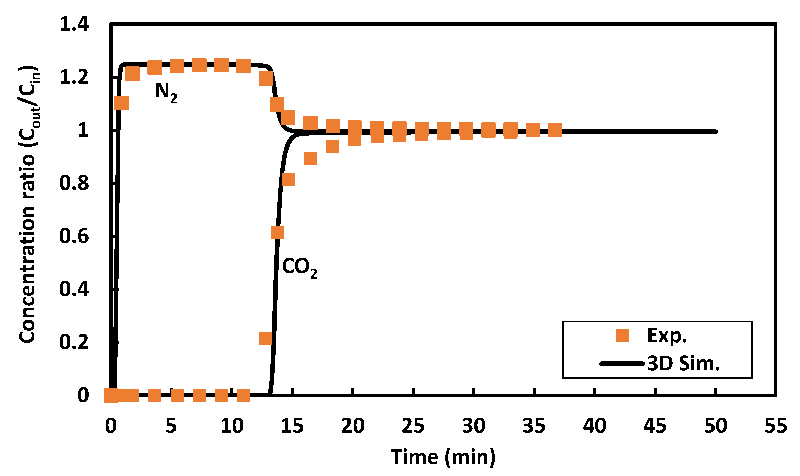
The mesh independence is studied for four mesh schemes listed in Table 2. It could be observed that the mesh number of >72,000 is sufficient to ensure precise results. For this study, the mesh size was taken >100,000 for all investigated cases. The model results are validated against experimental data of our previous work [23], as shown in Figure 2. An excellent agreement is observed between the numerical results and the experimental breakthrough curves of CO2 and N2 concentration ratios. The investigated numerical cycle is taken as the stable cyclic one when the difference between adsorption and desorption uptakes remains constant.

3. Results and Discussion

The results of the investigated three beds are discussed in this section, mainly in terms of CO2 uptake and bed temperature during the adsorption and desorption processes.

3.1. The General Behavior of Adsorption/Desorption Processes

The overall picture of the adsorption/desorption processes for the three beds can be obtained from the temporal temperature and uptake CO2 contours of the symmetry plane that shows the sorption behavior along the beds. The adsorption process is given 1100 s to ensure CO2 saturation (the inlet and surrounding temperatures are 25 °C). After that, up to 1800 s is given for the desorption process under heating from the external surface (120 °C). Figure 3 shows the temperature contours for the circular, square, and triangular cross-sectional beds at some selective adsorption and desorption times. During the adsorption process, the hot spots exist in the middle of the bed and crawl as time passes due to the adsorption process. As the adsorption process is exothermic, the regions that continue adsorbing CO2 are hot. The places at the bed center are hotter than those closer to external surfaces due to the good cooling process closer to the surfaces. For the desorption process, the hotter zones are closer to the external walls where the heating is applied.
The difference between the three-bed geometries is that the triangular one has hot regions (during the adsorption process) closer to the bottom since the distance between the top region and external surfaces is shorter than that in the middle. Thus, the top region of the triangular bed quickly becomes colder during the adsorption process and hotter during the desorption process.
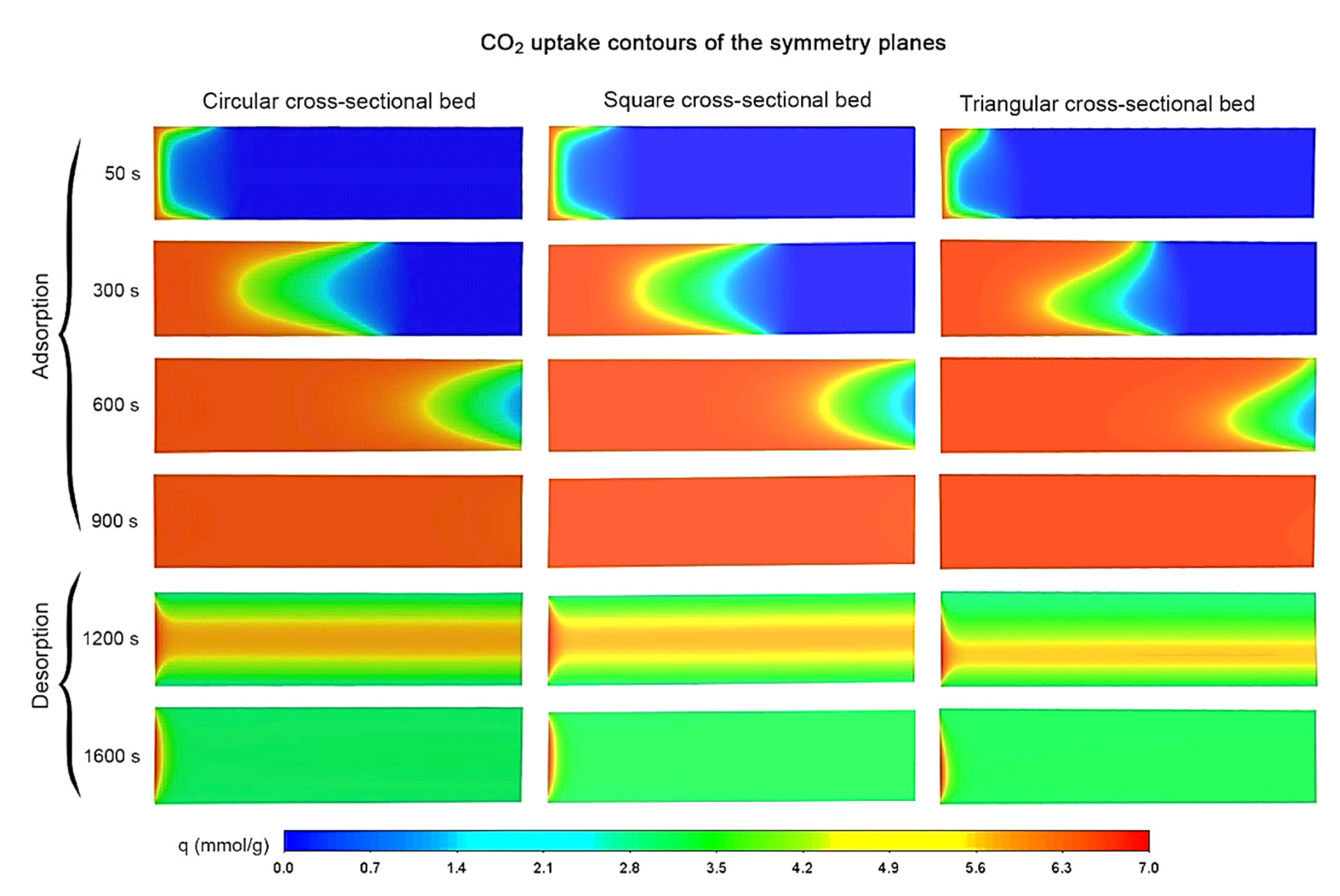
The temperature distribution along the bed is obtained from the applied conditions and the sorption processes. Figure 4 shows the CO2 uptake during the adsorption and desorption processes. The CO2 uptake is higher for colder zones (closer to the surfaces) and increases along the bed; the red zones show the regions that are saturated with CO2. At t = 900 s, all the beds reach the saturated uptake. Applying the heating process leads to a desorption process that expels the CO2 out from the bed. As the heating process is applied from the external surfaces, the regions closer to these surfaces are first regenerated. Again, the circular and square beds have similar adsorption and desorption uptake distribution, unlike the triangular one, in which the symmetry plane shows more adsorption/desorption at the top zones closer to the external surfaces.
Despite Figure 3 and Figure 4 showing the sorption behavior along the beds, the difference between beds in terms of higher uptake and better temperature dissipation can not be concluded from such plots. Therefore, the 2D profiles are discussed in the following sections.

3.2. Adsorption Concentration

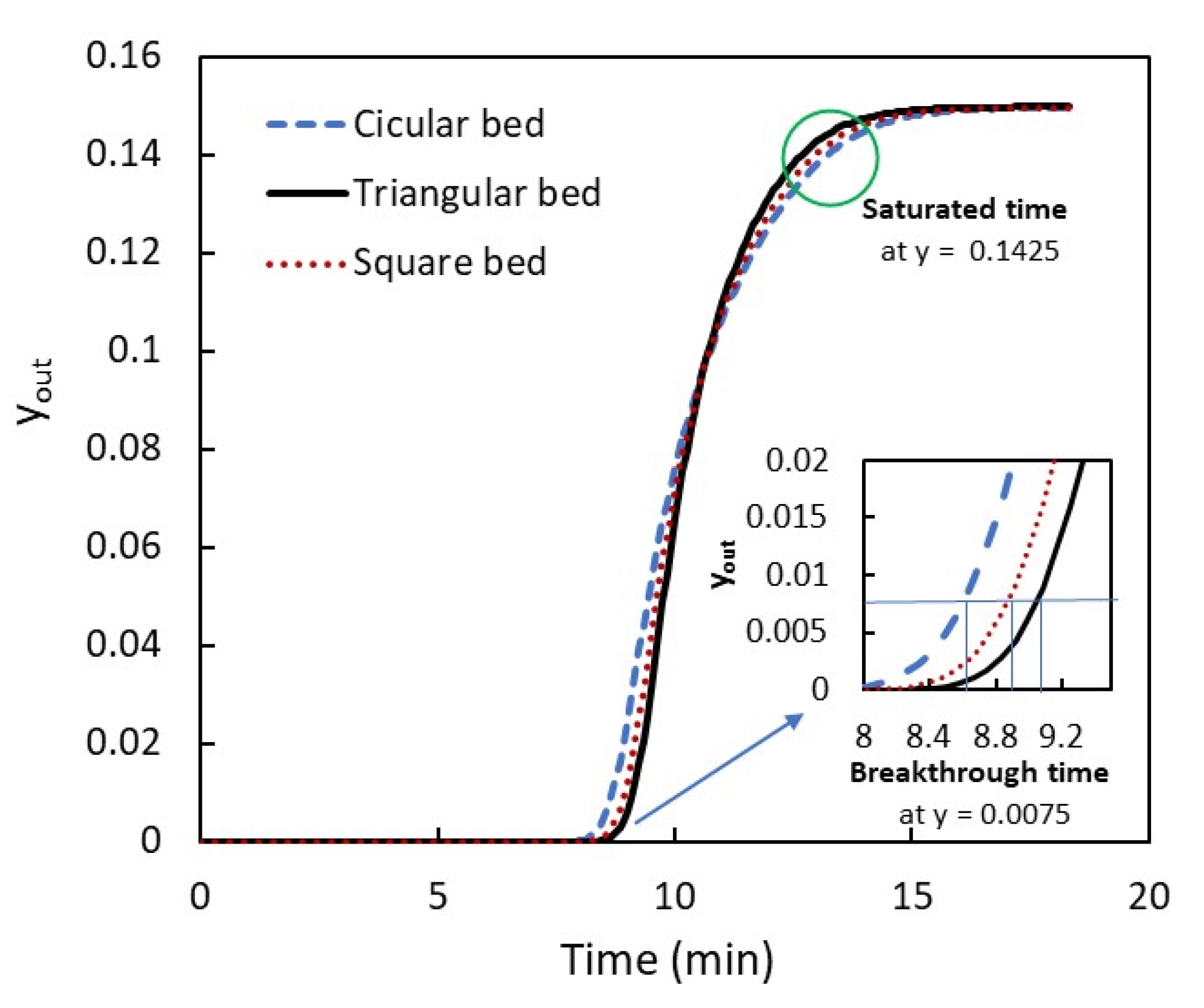
The adsorption concentration in terms of the CO2 molar fraction at bed exits is shown in Figure 5. As the inlet CO2 molar fraction is 0.15, the saturation conditions are reached when the CO2 outlet has 95% of the CO2 inlet (y = 0.1425). However, when the CO2 outlet reaches 5% of the CO2 inlet (y = 0.0075), this status is called the breakthrough point. The breakthrough point is for the CO2 separation applications to avoid the release of CO2 into the atmosphere. This means that, in real applications, the adsorption process should be stopped at the breakthrough point. It is obvious from Figure 5 that the triangular cross-sectional bed has a higher breakthrough time and lower saturation time, which are preferable. The higher breakthrough adsorption time means that the bed is able to adsorb more CO2, whereas a lower saturation time indicates a quick sorption process. The square cross-sectional bed comes second in terms of this advantage, while the circular one comes last. These results could be explained by the good cooling process during the adsorption process closer to the three corners of the triangular cross-section, which enables the bed to adsorb more CO2. The cooling process is better for the triangular bed than the square bed.

3.3. Adsorption Uptake

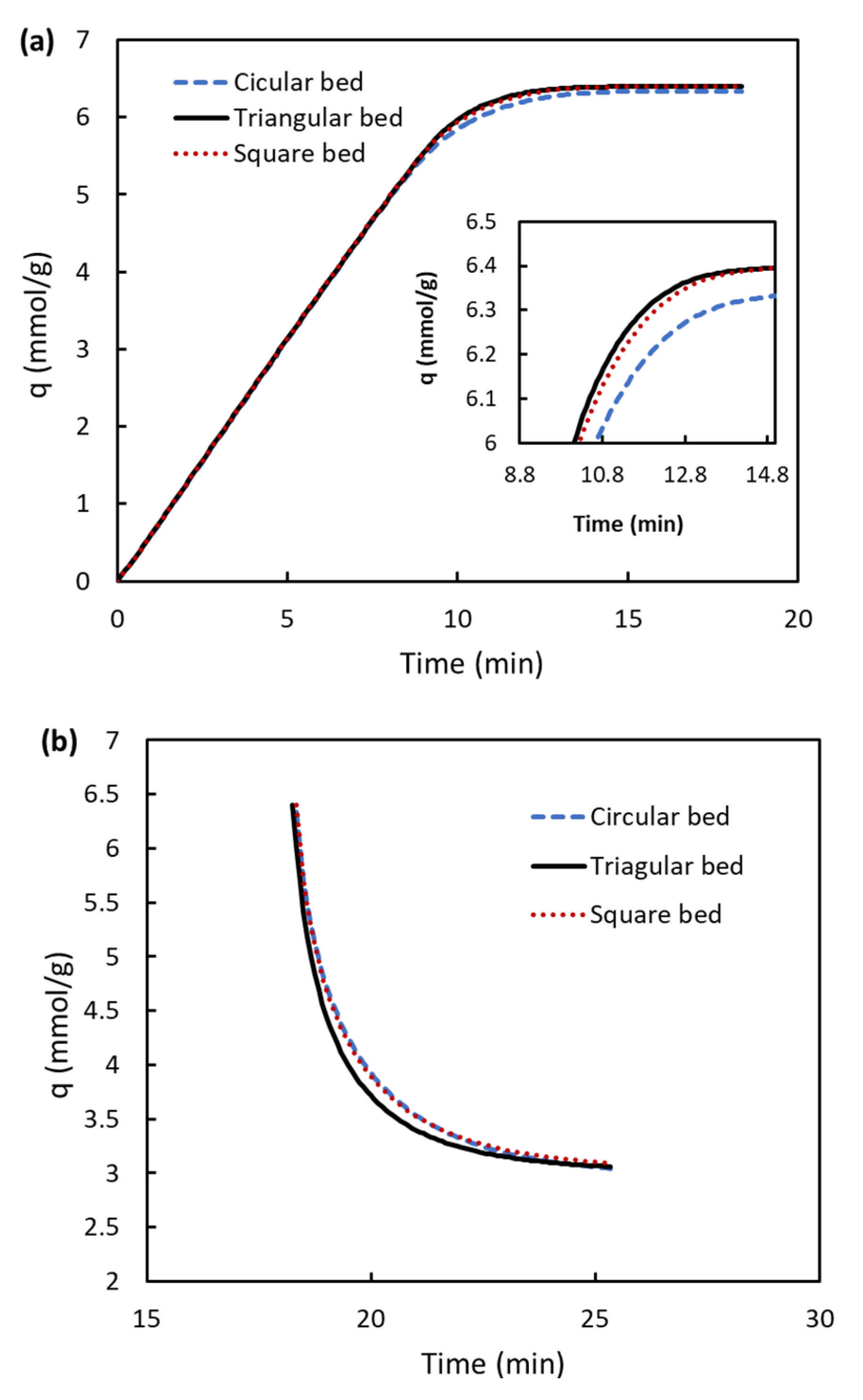
The adsorption uptake represents the ability of the bed to efficiently adsorb or desorb the desirable gas. A greater uptake shows that the bed capacity is high due to good cooling processes, and low uptake during the regeneration process indicates an efficient heating process. Of the three examined beds, the triangular one shows the greatest capacity during the adsorption process (Figure 6a) and the lowest capacity for an adequate desorption process time (Figure 6a). The square cross-sectional bed also has good uptake values. The difference between the three beds is not high (e.g., at t = 10.8 min, adsorption uptake is 6.04 mmol/g for the circular bed, 6.13 mmol/g for the square bed, and 6.17 mmol/g for the triangular bed); however, the square bed is best for large and industrial scales. In addition, for large scales, the triangular cross-sectional beds can be arranged compactly, compared to circular ones, which have cavities between beds. Figure 6 exhibits, in general, an increase in the adsorption uptake with time until the bed is saturated during the adsorption process, and the opposite occurs during the desorption process.

3.4. Temperature Profiles during Adsorption and Regeneration Processes

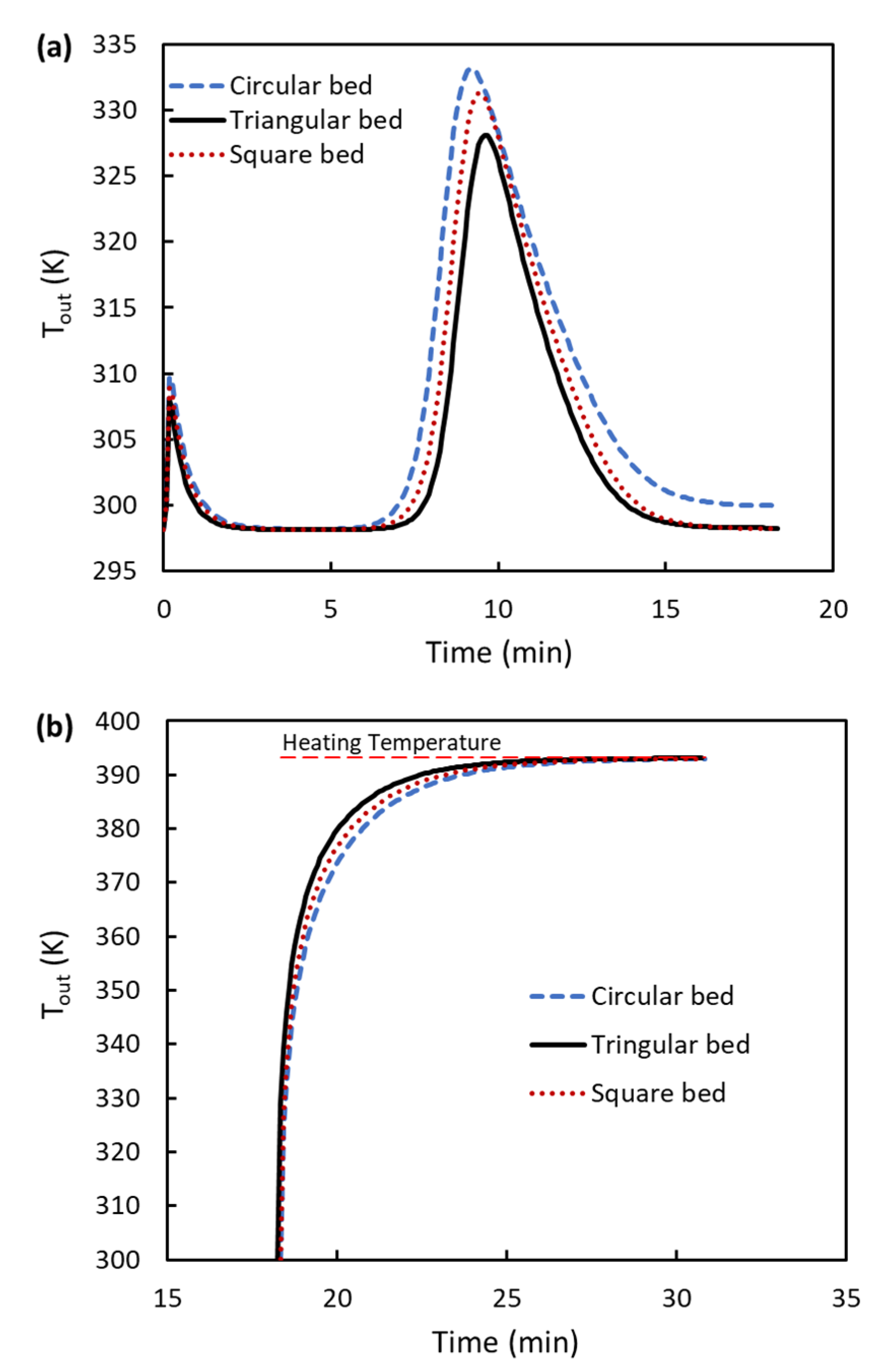
Temperature values increase in the bed during the adsorption process due to the exothermic phenomenon of the adsorption. An increment in bed temperature has a negative impact on the adsorption capacity, so a bed design that can minimize increases in temperature values is desirable. Figure 7a shows that the outlet temperature of the triangular cross-sectional bed has the lowest temperature values. Its maximum temperature (during the adsorption process) is about 327 K, which is lower than that of the circular bed by 6 K. Figure 7b also emphasizes the merits of the triangular bed in reaching higher temperatures quickly during the desorption process. The triangular cross-section has three corners that raise the bed temperature closer to the surfaces than the core. The core of the circular cross-sectional bed is wider, so the heating process takes time since the thermal conductivity of adsorbent materials is very low (~0.3 W/m·K).

3.5. Pressure Drop

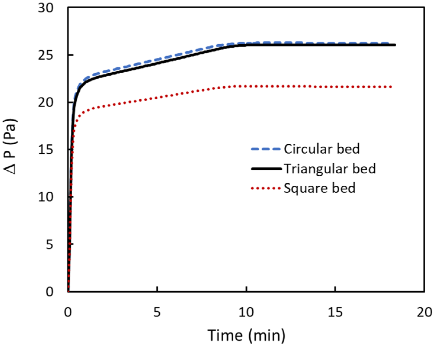
Since the three beds have the same cross-sectional area and length, the pressure drop could be assumed to be the same. However, this is not true because the triangular cross-section has three corners, the square cross-section has four corners, and the circular cross-section has no corners. The beds are also porous, and the particle distribution inside the beds affects the flow resistance and pressure drop. Figure 8 shows a slight pressure drop for the triangular cross-sectional bed that is less than the circular one. However, the square cross-sectional bed has the minimum pressure drop, which suggests that such beds are better suited for pressure swing adsorption rather than temperature swing adsorption. The maximum pressure drop per unit meter is about 108.5 Pa/m for the square cross-sectional bed, 130.5 Pa/m for the triangular cross-sectional bed, and 131.5 Pa/m for the circular cross-sectional bed. According to the above results, triangular cross-sectional beds perform well with temperature swing adsorption when pumping power is not important. When considering both CO2 uptake and pumping power, one may select the square cross-sectional beds. The advantage of triangular and square beds is their arrangement in the package of a bank of tubes for industrial scales with appropriate cooling clearance between the tubes. Circular cross-sectional beds used in the literature have bed packing arrangements with non-uniform spaces between the tubes.

4. Conclusions

Three beds with different cross-sectional area shapes (circular, square, and triangular) are investigated to enhance thermal characteristics (heating and cooling) during the sorption processes of carbon capture. The cross-sectional area and bed length are the same for systematic comparison. Mg-MOF-74, as an excellent adsorbent, is used in this study. The CFD model is developed by a user-defined function coupled with commercial ANSYS-Fluent software. The model is validated against the experimental work completed previously by the authors. Based on the applied conditions, we present the following conclusions:
  • Temperature values along the bed are lower for triangular cross-sectional beds than others, improving the adsorption and desorption processes. About 6 K is the reduction in temperature when a triangular cross-sectional bed is used compared to a circular one.
  • Due to an enhancement in temperature cooling and heating of the triangular bed, the CO2 adsorption uptake has higher values for this bed than others.
  • The pressure drop is lower for the square bed, about 17% less than the circular one. The triangular bed has slightly lower values compared to the circular beds.
Based on the above points, triangular cross-sectional beds could be an excellent candidate when pumping power is not important for temperature swing adsorption plants in which a bank of tubes is compact together with proper cooling between them. The circular beds suggested in the literature are less compact. The square beds could be suitable for pressure swing adsorption as the pressure drop is low. Furthermore, the square bed is the correct choice when considering both pumping power and CO2 uptake.

Author Contributions

Conceptualization, N.A.A.Q.; Data curation, R.B.-M.; Formal analysis, N.A.A.Q.; Funding acquisition, R.B.-M.; Methodology, N.A.A.Q.; Project administration, R.B.-M.; Software, N.A.A.Q. All authors have read and agreed to the published version of the manuscript.

Funding

This research was funded by KFUPM grant number SB191021.

Informed Consent Statement

Not Applicable.

Data Availability Statement

Not applicable.

Acknowledgments

The authors thank the support received from the Deanship of Research Oversight and Coordination, King Fahd University of Petroleum & Minerals (KFUPM), Dhahran, Saudi Arabia, under Project SB191021.

Conflicts of Interest

The authors declare no conflict of interest.

References

  1. Ben-Mansour, R.; Habib, M.A.; Bamidele, O.E.; Basha, M.; Qasem, N.A.A.; Peedikakkal, A.; Laoui, T.; Ali, M. Carbon capture by physical adsorption: Materials, experimental investigations and numerical modeling and simulations—A review. Appl. Energy 2016, 161, 225–255. [Google Scholar] [CrossRef]
  2. Shah, G.; Ahmad, E.; Pant, K.K.; Vijay, V.K. Comprehending the contemporary state of art in biogas enrichment and CO2 capture technologies via swing adsorption. Int. J. Hydrog. Energy 2021, 46, 6588–6612. [Google Scholar] [CrossRef]
  3. D’Alessandro, D.M.; McDonald, T. Toward carbon dioxide capture using nanoporous materials. Pure Appl. Chem. 2010, 83, 57–66. [Google Scholar] [CrossRef]
  4. Ahsan, S.; Ayub, A.; Meeroff, D.; Lashaki, M.J. A comprehensive comparison of zeolite-5A molecular sieves and amine-grafted SBA-15 silica for cyclic adsorption-desorption of carbon dioxide in enclosed environments. Chem. Eng. J. 2022, 437, 135139. [Google Scholar] [CrossRef]
  5. Yao, X.; Cordova, K.E.; Zhang, Y.-B. Flexible Metal–Organic Frameworks as CO2 Adsorbents en Route to Energy-Efficient Carbon Capture. Small Struct. 2022, 3, 2100209. [Google Scholar] [CrossRef]
  6. Bermeo, M.; Vega, L.F.; Abu-Zahra, M.R.M.; Khaleel, M. Critical assessment of the performance of next-generation carbon-based adsorbents for CO2 capture focused on their structural properties. Sci. Total Environ. 2022, 810, 151720. [Google Scholar] [CrossRef] [PubMed]
  7. Akeeb, O.; Wang, L.; Xie, W.; Davis, R.; Alkasrawi, M.; Toan, S. Post-combustion CO2 capture via a variety of temperature ranges and material adsorption process: A review. J. Environ. Manag. 2022, 313, 115026. [Google Scholar] [CrossRef]
  8. Bai, R.; Song, X.; Yan, W.; Yu, J. Low-Energy Adsorptive Separation by Zeolites. Natl. Sci. Rev. 2022, nwac064. [Google Scholar] [CrossRef]
  9. Jung, W.; Lee, J. Economic evaluation for four different solid sorbent processes with heat integration for energy-efficient CO2 capture based on PEI-silica sorbent. Energy 2022, 238, 121864. [Google Scholar] [CrossRef]
  10. Samanta, A.; Zhao, A.; Shimizu, G.K.H.; Sarkar, P.; Gupta, R. Post-combustion CO2 capture using solid sorbents: A review. Ind. Eng. Chem. Res. 2012, 51, 1438–1463. [Google Scholar] [CrossRef]
  11. Siriwardane, R.V.; Shen, M.-S.; Fisher, E.P.; Poston, J.A. Adsorption of CO 2 on Molecular Sieves and Activated Carbon. Energy Fuels 2001, 15, 279–284. [Google Scholar] [CrossRef]
  12. Qasem, N.A.A.; Ben-Mansour, R. Energy and productivity efficient vacuum pressure swing adsorption process to separate CO2 from CO2/N2 mixture using Mg-MOF-74: A CFD simulation. Appl. Energy 2018, 209, 190–202. [Google Scholar] [CrossRef]
  13. Qasem, N.A.A.; Qadir, N.U.; Ben-Mansour, R.; Said, S.A.M. Synthesis, characterization, and CO2 breakthrough adsorption of a novel MWCNT/MIL-101(Cr) composite. J. CO2 Util. 2017, 22, 238–249. [Google Scholar] [CrossRef]
  14. Li, L.; Jung, H.S.; Lee, J.W.; Kang, Y.T. Review on applications of metal–organic frameworks for CO2 capture and the performance enhancement mechanisms. Renew. Sustain. Energy Rev. 2022, 162, 112441. [Google Scholar] [CrossRef]
  15. Pentyala, V.; Davydovskaya, P.; Ade, M.; Pohle, R.; Urban, G. Carbon dioxide gas detection by open metal site metal organic frameworks and surface functionalized metal organic frameworks. Sens. Actuators B Chem. 2016, 225, 363–368. [Google Scholar] [CrossRef]
  16. Qasem, N.A.A.; Ben-Mansour, R. Adsorption breakthrough and cycling stability of carbon dioxide separation from CO2/N2/H2O mixture under ambient conditions using 13X and Mg-MOF-74. Appl. Energy 2018, 230, 1093–1107. [Google Scholar] [CrossRef]
  17. Ben-Mansour, R.; Qasem, N.A.A.; Antar, M.A. Carbon dioxide adsorption separation from dry and humid CO2/N2 mixture. Comput. Chem. Eng. 2018, 117, 221–235. [Google Scholar] [CrossRef]
  18. Qasem, N.A.A.; Abuelyamen, A.; Ben-Mansour, R. Enhancing CO2 Adsorption Capacity and Cycling Stability of Mg-MOF-74, Arab. J. Sci. Eng. 2021, 46, 6219–6228. [Google Scholar] [CrossRef]
  19. Adhikari, A.K.; Lin, K.-S. Improving CO2 adsorption capacities and CO2/N2 separation efficiencies of MOF-74(Ni, Co) by doping palladium-containing activated carbon. Chem. Eng. J. 2016, 284, 1348–1360. [Google Scholar] [CrossRef]
  20. Lee, D.J.; Li, Q.; Kim, H.; Lee, K. Preparation of Ni-MOF-74 membrane for CO2 separation by layer-by-layer seeding technique. Microporous Mesoporous Mater. 2012, 163, 169–177. [Google Scholar] [CrossRef]
  21. Cho, H.Y.; Yang, D.A.; Kim, J.; Jeong, S.Y.; Ahn, W.S. CO2 adsorption and catalytic application of Co-MOF-74 synthesized by microwave heating. Catal. Today 2012, 185, 35–40. [Google Scholar] [CrossRef]
  22. Ben-Mansour, R.; Qasem, N.A.A.; Habib, M.A. Adsorption characterization and CO2 breakthrough of MWCNT/Mg-MOF-74 and MWCNT/MIL-100(Fe) composites. Int. J. Energy Environ. Eng. 2018, 9, 169–185. [Google Scholar] [CrossRef] [Green Version]
  23. Abdelnaby, M.M.; Qasem, N.A.A.; Al-Maythalony, B.A.; Cordova, K.E.; Al Hamouz, O.C.S. A Microporous Organic Copolymer for Selective CO2 Capture under Humid Conditions, ACS Sustain. Chem. Eng. 2019, 7, 13941–13948. [Google Scholar] [CrossRef]
  24. Ben-Mansour, R.; Abuelyamen, A.; Qasem, N.A.A. Thermal design and management towards high capacity CO2 adsorption systems. Energy Convers. Manag. 2020, 212, 112796. [Google Scholar] [CrossRef]
  25. Al Mesfer, M.K.; Danish, M.; Khan, M.I.; Ali, I.H.; Hasan, M.; Jery, A.E. Continuous Fixed Bed CO2 Adsorption: Breakthrough, Column Efficiency, Mass Transfer Zone. Processes 2020, 8, 1233. [Google Scholar] [CrossRef]
  26. Wang, S.; Li, Y.; Li, Z. Fast Adsorption Kinetics of CO2 on Solid Amine Sorbent Measured Using Microfluidized Bed Thermogravimetric Analysis. Ind. Eng. Chem. Res. 2020, 59, 6855–6866. [Google Scholar] [CrossRef]
  27. Jung, W.; Park, S.; Lee, K.S.; Jeon, J.-D.; Lee, H.K.; Kim, J.-H.; Lee, J.S. Rapid thermal swing adsorption process in multi-beds scale with sensible heat recovery for continuous energy-efficient CO2 capture. Chem. Eng. J. 2020, 392, 123656. [Google Scholar] [CrossRef]
  28. Boscherini, M.; Miccio, F.; Papa, E.; Medri, V.; Landi, E.; Doghieri, F.; Minelli, M. The relevance of thermal effects during CO2 adsorption and regeneration in a geopolymer-zeolite composite: Experimental and modelling insights. Chem. Eng. J. 2021, 408, 127315. [Google Scholar] [CrossRef]
  29. Abd, A.A.; Othman, M.R. Biogas upgrading to fuel grade methane using pressure swing adsorption: Parametric sensitivity analysis on an industrial scale. Fuel. 2022, 308, 121986. [Google Scholar] [CrossRef]
  30. Ben-Mansour, R.; Basha, M.; Qasem, N.A.A. Multicomponent and multi-dimensional modeling and simulation of adsorption-based carbon dioxide separation. Comput. Chem. Eng. 2017, 99, 255–270. [Google Scholar] [CrossRef]
  31. Xiao, J.; Peng, R.; Cossement, D.; Bénard, P.; Chahine, R. CFD model for charge and discharge cycle of adsorptive hydrogen storage on activated carbon. Int. J. Hydrog. Energy 2013, 38, 1450–1459. [Google Scholar] [CrossRef]
  32. Dantas, T.L.P.; Murilo, F.; Luna, T.; Silva, I.J.; de Azevedo, D.C.S.; Grande, C.A.; Rodrigues, A.E.; Moreira, R.F.P.M. Carbon dioxide—Nitrogen separation through adsorption on activated carbon in a fixed bed. Chem. Eng. J. 2011, 169, 11–19. [Google Scholar] [CrossRef]
  33. Dantas, T.L.P.; Murilo, F.; Luna, T.; Silva, I.J.; Eurico, A.; Torres, B.; de Azevedo, D.C.S.; Rodrigues, A.E.; Moreira, R.F.P.M. Carbon dioxide—Nitrogen separation through pressure swing adsorption. Chem. Eng. J. 2011, 172, 698–704. [Google Scholar] [CrossRef]
  34. Incropera, F.P.; DeWitt, D.P.; Bergman, T.L.; Lavine, A.S. Fundamentals of Heat and Mass Transfer; John Wiley & Sons: Hoboken, NJ, USA, 2007. [Google Scholar] [CrossRef]
  35. Ben-Mansour, R.; Qasem, N.A.A. An efficient temperature swing adsorption (TSA) process for separating CO2 from CO2/N2 mixture using Mg-MOF-74. Energy Convers. Manag. 2018, 156, 10–24. [Google Scholar] [CrossRef]
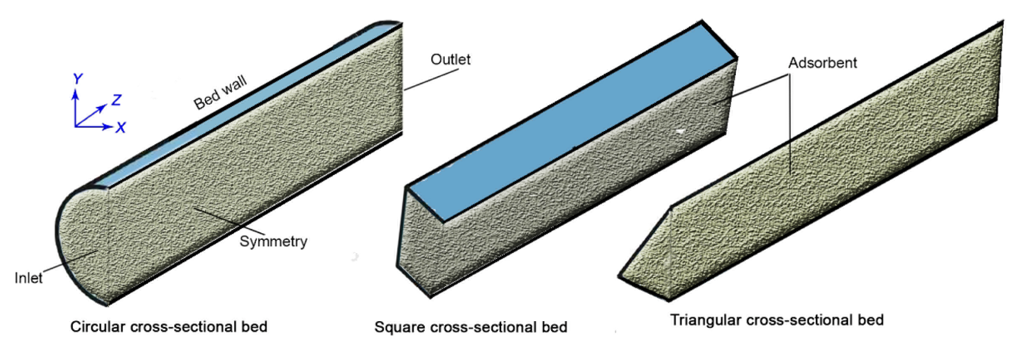
Figure 1. Adsorption beds investigated in this study.
Applsci 12 05726 g001
Figure 2. Breakthrough concentration ratio of CO2 and N2 at the bed outlet during the adsorption process using Mg-MOF-74 to compare the 3D simulation with the experimental data (at bed porosity = 0.674, particle size = 0.2 mm, bed length = 7 cm, bed diameter = 0.4 cm) [23]. Mg-MOF-74 is synthesized and characterized in the previous study [22].
Applsci 12 05726 g002
Figure 3. Temperature contours for the investigated beds at selective adsorption and desorption times.
Applsci 12 05726 g003
Figure 4. CO2 uptake contours for the investigated beds at selective adsorption and desorption times.
Applsci 12 05726 g004
Figure 5. Carbon dioxide molar fraction at bed exit during the adsorption process (yin = 0.15).
Applsci 12 05726 g005
Figure 6. CO2 adsorption uptake during (a) adsorption process and (b) desorption process for the investigated beds.
Applsci 12 05726 g006
Figure 7. Temperature profiles during (a) adsorption process and (b) desorption process for the investigated beds.
Applsci 12 05726 g007
Figure 8. Pressure drop during the adsorption process for the investigated beds.
Applsci 12 05726 g008
Table 1. Thermal properties, adsorbent bed construction, and applied boundary conditions.
ParameterValue
Bed length, m0.20
Bed cross-sectional area, cm23.1416
Bed density (kg/m3)297 [16]
Adsorbent thermal conductivity (W/m·K)0.3 [35]
Adsorbent heat capacity (J/kg·K)900 [35]
Particle density, ρp (kg/m3)911 [35]
Bed porosity, ε0.674 [16]
qm1,CO2 (Equation (4)) (mol/kg)6.80 [16]
qm2,CO2 (Equation (4)) (mol/kg)9.9 [16]
qm1,N2 (Equation (4)) (mol/kg)14.0 [16]
qm2,N2 (Equation (4)) (mol/kg)0 [16]
Ko1,CO2 (Equation (4)) (1/Pa)2.44 × 10−11 [16]
Ko2,CO2 (Equation (4)) (1/Pa)1.39 × 10−10 [16]
Ko1,N2 (Equation (4)) (1/Pa)4.96 × 10−10 [16]
Ko2,N2 (Equation (4)) (1/Pa)0 [16]
ΔH1,CO2 (Equation (4)) (J/mol)−42,000 [16]
ΔH2,CO2 (Equation (4)) (J/mol)−24,000 [16]
ΔH1,N2 (Equation (4)) (J/mol)−18,000 [16]
ΔH2,N2 (Equation (4)) (J/mol)0 [16]
KL,CO2 (Equation (3)) (1/s)0.1213 [16]
KL,N2 (Equation (3)) (1/s)0.3055 [16]
CO2 adsorption heat (Equation (8)), ΔHCO2 (J/mol)−(42,492.6 – 6568.83 q + 3973.75 q2 − 959.838 q3 + 69.1208 q4) J mol−1 (0 < q < 7.5 mmol g−1) [16]
N2 adsorption heat (Equation (8)), ΔHN2 (J/mol)−18,000 [16]
Inlet velocity during adsorption, m/s0.1
Pressure outlet during adsorption, kPa101.3
Inlet temperature during adsorption, K298
Inlet velocity during desorption, m/s0
Wall temperature during adsorption, KEquation (11)
Wall temperature during desorption, K393
Table 2. Mesh independence study in terms of the bed Tavg.
Cells Number714032,00072,500102,000
Tavg (K)312.86312.17309.48309.20
Publisher’s Note: MDPI stays neutral with regard to jurisdictional claims in published maps and institutional affiliations.