Article

Parameter Identification of Structures with Different Connections Using Static Responses

1
Department of Civil Engineering, Nanjing University of Science and Technology, Nanjing 210094, China
2
College of IT and Engineering, Marshall University, Huntington, WV 25755, USA
*
Author to whom correspondence should be addressed.
Appl. Sci. 2022, 12(12), 5896; https://doi.org/10.3390/app12125896
Submission received: 21 April 2022 / Revised: 3 June 2022 / Accepted: 6 June 2022 / Published: 9 June 2022

Abstract

:
This paper presents a parameter-identification method for rod structures with different connections. In this method, the parameters of the structure are adjusted to match its analytical and measured displacements. The damage identification for truss structure and rigid frame were investigated. Previous studies often considered the cross-sectional area damage or joint damage; there are few studies on the simultaneous existence of these two types of damage. In this study, damage identification for a rigid frame with both cross-sectional and joint damage was performed. Based on the measured displacements, the proposed method can accurately identify the cross-sectional and joint damage for a rigid frame.

1. Introduction

Damage to one or more components of the structure causes changes in the physical properties of the structure, especially at the damaged location, which will cause the “as-is” condition of the structure to be different from the design [1,2,3]. Therefore, it is becoming increasingly important to assess the condition of the existing structures. At the same time, there is a growing need for a reliable method to monitor the performance of structures. The safety of these damaged structures can be detected using parameter identification. It is a mathematical method that uses the error between the estimated and experimental values. It correlates the changes in the test data with those in the characteristics of the structural element [4]. The purpose of parameter identification is to adjust the parameters of a structure to match the analytical and measured data [5]. Budipriyanto [6] introduced the application of blind-source-separation technology to identify the dynamic parameters of a seismic-excited multi-story frame building from the measured responses. Bu et al. [7] proposed an improved wavelet Galerkin method, which was applied for the simultaneous identification and excitation of the parameters of a shear frame with non-uniform stiffness subjected to seismic excitation. Sanayei et al. [8] presented a method to identify the cross-sectional properties of truss and frame structural elements by applying static forces and then measuring the displacements. Furthermore, using static responses, Terlaje III et al. [9] presented a new method and algorithm to identify damage in a truss structure and a frame structure using a limited number of simulated applied loads and measured displacements. Xiao et al. [10,11] proposed an optimal placement method of static strain sensors based on damage identification for truss structures and compared the recognition effects of different optimization methods. These studies conducted considerable research on the damage identification of rod structures with different connections, including error analysis, optimal placement of sensors, and comparison of various optimization methods, and the structures that were investigated included truss and rigid frame structures.
In practical engineering construction, several joints in frame structures are of semi-rigid connection type owing to the design or damage; the characteristics of semi-rigid connections lie fall in between those of pin and rigid connections. Notably, some studies on structures with semi-rigid connections have been conducted [12,13,14,15,16,17]. Reyes-Salazar and Haldar [12] evaluated and analyzed the nonlinear seismic response of steel structures with semi-rigid and composite connections in terms of maximum interstory and maximum top lateral displacements. Llanes-Tizoc et al. [13] carried out a numerical study on the reliability of 3D steel structures with perfectly pinned connections and semi-rigid connections under seismic loads. Rigi et al. [14] studied seismic performance of steel moment-resisting frames with different degrees of moment connection rigidities.
Several methods have been presented to identify joint damage for frame structures and to reduce the error during model updating by varying the rigidity of the element connections. Yi et al. [18] proposed an approach to identify the joint damage in steel frame structures using dynamic and static measurement data. Altunişik et al. [19] presented a method for updating the finite-element model of an arch-type steel-laboratory bridge model with semi-rigid connections. Machavaram et al. [20] presented a novel two-stage improved radial basis function neural network technique to identify the joint damage of a semi-rigid frame structure in frequency and time domains. Nanda et al. [21] proposed a joint damage identification method based on modal parameters using a unified particle swarm optimization method to identify joint damages in any frame structure. Pal et al. [22] presented a joint damage identification technique using the numerical model of a semi-rigid frame to quantify the level of loosening of bolted joints in a steel frame structure, based on vibrations. Seyedpoor et al. [23] introduced a two-step method for joint damage identification for steel frames using a support vector machine and a differential evolution algorithm. Hou et al. [24] proposed a two-step damage-detection method for space-frame structures with semi-rigid connections. Numerous studies have identified cross-sectional damage in trusses and rigid frames. In addition, in some studies, joint damage was identified for semi-rigid frame structures on the basis of static and modal data. However, there are few studies utilizing static measurements for damage identification in rigid frame structures having both cross-sectional and joint damage. Therefore, this paper presents a new method to identify the damage in frame structures with both cross-sectional and joint damage.

2. Formulation for Parameter Identification

In the parameter-identification algorithm, the difference between the analytical and measured displacements is defined using the objective function. The unknown parameters can be obtained by determining the global-minimum value of the objective function. In this method, adequate excitation is imparted to the structure using the applied static forces. The damage condition of the components of the structure was determined on the basis of the measurement of nodal displacements of the structure.
The analytical displacements can be obtained using the stiffness method [25]. This method is based on the force-displacement relationship for the structure, as expressed in Equation (1):
Q = K D
where Q and D represent the global forces and displacements, respectively; K is the entire-structure stiffness matrix that can be obtained by assembling the member stiffness matrix in global coordinates, k, where k = TT kT, where k′ is the member stiffness matrix in local coordinates, and T is referred to as displacement transformation matrix. K contains P, which is a set of unknown parameters (such as unknown cross-sectional area Au, unknown moment of inertia Iu, unknown nodal rotational stiffness Ru) that need to be identified. Equation (1) can be divided to separate the known and unknown displacements as under:
[ Q k Q u ] = [ K 11 K 12 K 21 K 22 ] [ D u D k ]
where Qk and Dk are the known external loads and boundary conditions of the nodal displacements, respectively. Qu and Du are the unknown loads and boundary conditions of the nodal displacements, respectively. By solving Equation (2), we obtain:
D u = K 11 1 ( Q k K 12 D k )
The objective function is defined as the sum of the square of the difference between the analytical displacement Du and measured displacement Dm; n is the total number of measured displacements.
f = i = 1 n ( D u i D m i ) 2
The unknown parameter P of the structure can be obtained by minimizing the objective function. Assume that the optimal value of P is P, which can be determined using Equation (5):
P = arg min P ( f )
Rod structures are composed of elements and joints. The joints are used to transfer load from one structural element to another; the joints include pin, rigid, and semi-rigid connections. The form of member stiffness matrix k′ should be distinguished in the process of forming the damage-identification objective function for truss structure, rigid frame, and semi-rigid frame structures.

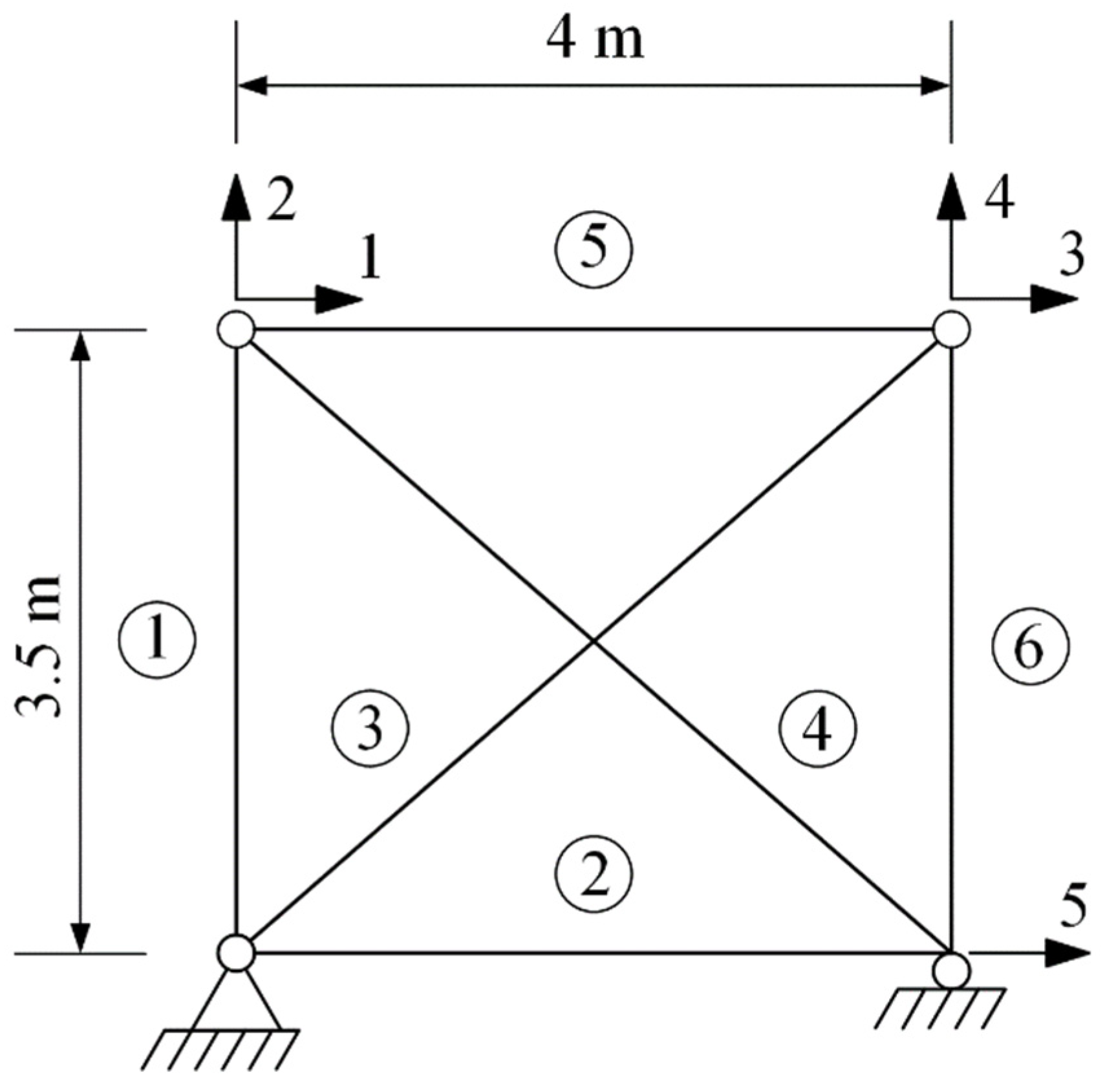
3. Parameter Identification for Truss

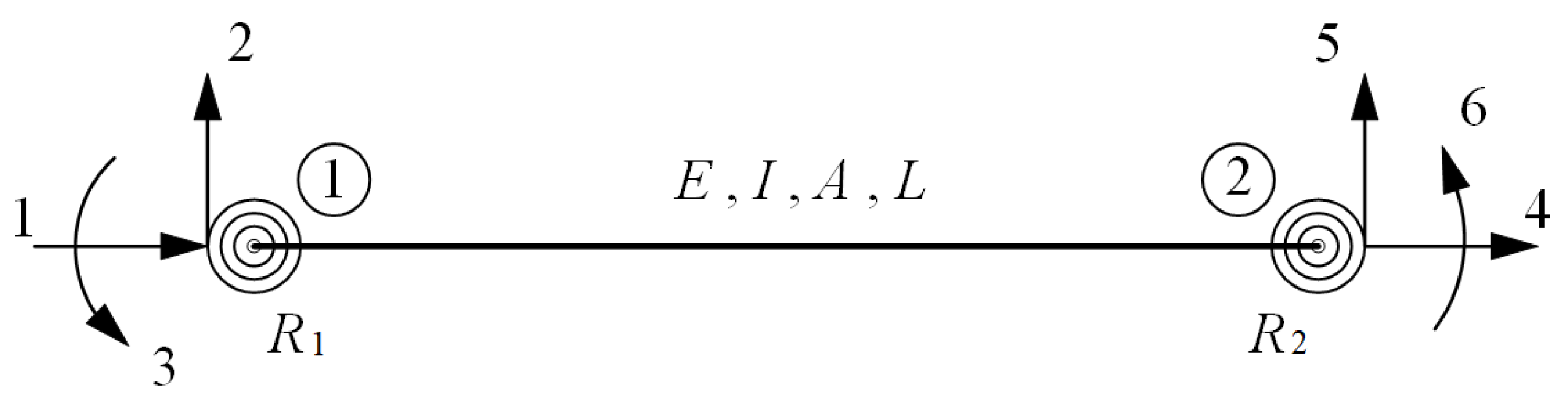
3.1. Member Stiffness Matrix of Truss

The joints of a truss are defined as pin connections. Theoretically, the pin connection does not provide resistance to rotation, and it behaves as a hinge. A truss member can only be displaced along its axis because loads are applied along this axis. Truss members are either under compression or tension, or have no force. The member stiffness matrix of truss structure is relatively simple owing to the simple stress of the truss structure. The member stiffness matrix of truss member [25] is given by Equation (6). The terms in this matrix represent the load-displacement relations for the corresponding member. Due to corrosion, cracks, etc., the cross-sectional area of a truss can be damaged, and the parameter P of the objective function is the unknown cross-sectional area Au, which is included in the following matrix:
k = A u E L [ 1 1 1 1 ]
where E is the modulus of elasticity and L is the length of the member.

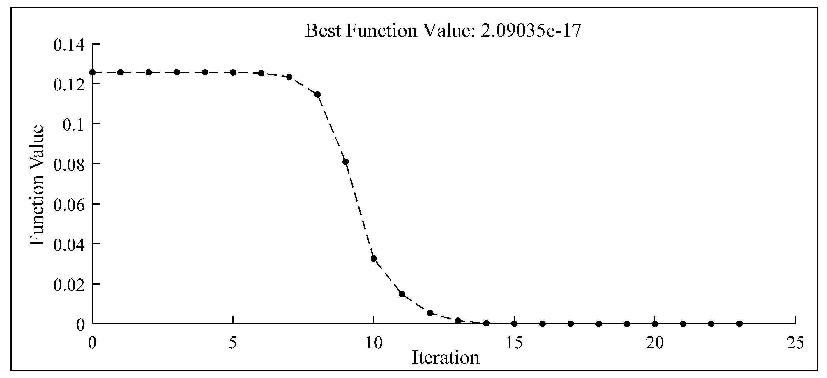
3.2. Parameter Identification for Truss Sample

A six-member truss (Figure 1) was used to demonstrate the parameter-identification method of the truss structure using static displacements. All members have identical cross-sectional geometric properties. The “as-built” condition of the six-member truss has cross-sectional areas of A = 3 × 10⁻³ m2 and a modulus of elasticity of 206 GPa. It is assumed that there is damage in members 1 and 4. The “as-is” cross-sectional areas of members 1 and 4 are 2.5 × 10⁻³ m2 and 2.75 × 10⁻³ m2, respectively. Since the “as-is” cross-sectional areas of members 1 and 4 are the parameters that need to be identified, therefore assuming the corresponding cross-sectional areas are A1 and A4, forces of −100 kN and 50 kN were applied along degrees of freedom 2 and 3 to excite the truss structure; subsequently, displacements Dm were measured along degrees of freedom 1 and 2.
In this study, the measured displacement was determined on the basis of the structural “as-is” condition.
The member stiffness matrix k′ of the truss member was obtained from Equation (6), and the objective function was obtained from Equation (4). The interior-point method [26] can converge quickly and solve complex problems with a large number of variables, and this method was used to minimize the objective function to realize the damage identification of the truss structure. According to the ‘‘as-built’’ condition, the starting point of cross-sectional variable A was set to 1.5 × 10⁻³, and the constraints on A were set between 0 and 3 × 10⁻³. After 23 iterations, the final optimal values of A1 and A4 were 2.500 × 10³ and 2.750 × 10⁻³ m2, respectively. Figure 2 shows the variation of A1 and A4 with the number of iterations; the dotted lines in the figure represent the “as-is” cross-sectional areas of members 1 and 4. Figure 3 shows the variation of the objective function with the number of iterations. The results demonstrate that A1 and A4 converged at 23 iterations.

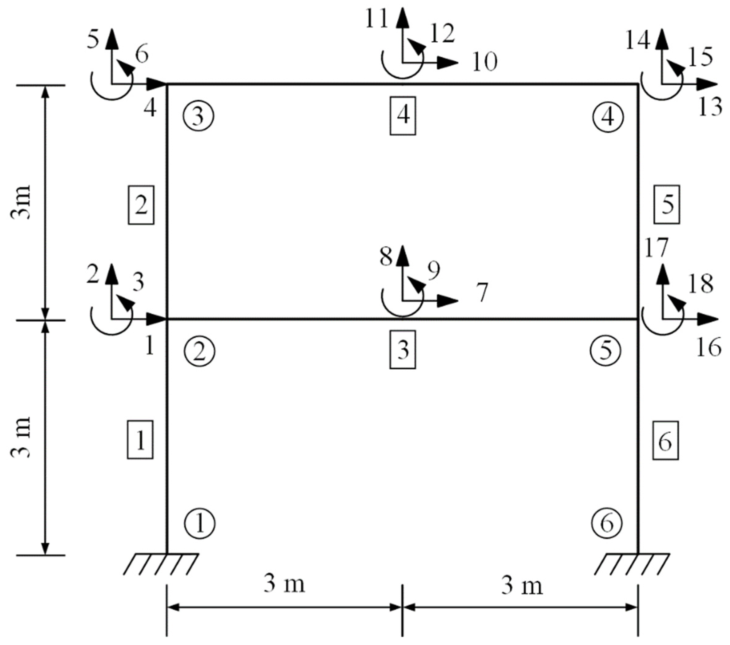
4. Parameter Identification for a Rigid Frame

4.1. Member Stiffness Matrix of a Rigid Frame

Various structures, such as bridges and multi-story industrial plants, are composed of frames. A frame is a rod structure consisting of beams and columns to resist loads. In contrast to the plane truss element, the plane frame is subjected to shear forces and bending moments in addition to axial forces. The member stiffness matrix of the plane frame [25] is given by Equation (7). This matrix has three degrees of freedom per joint and includes axial effects, as well as shear force effects and principal bending moment effects [27]. To consider the damage incurred in the structure, the cross-sectional area Au and moment of inertia Iu of the damaged member are included in the matrix, which constitute the unknown parameter P that needs to be identified.
k = [ A u E L 0 12 E I u L 3 S Y M 0 6 E I u L 2 4 E I u L A u E L 0 0 A u E L 0 12 E I u L 3 6 E I u L 2 0 12 E I u L 3 0 6 E I u L 2 2 E I u L 0 6 E I u L 2 4 E I u L ]
The terms in Equation (7) in addition to Au and Iu are the modulus of elasticity (E) and length (L) of the member.

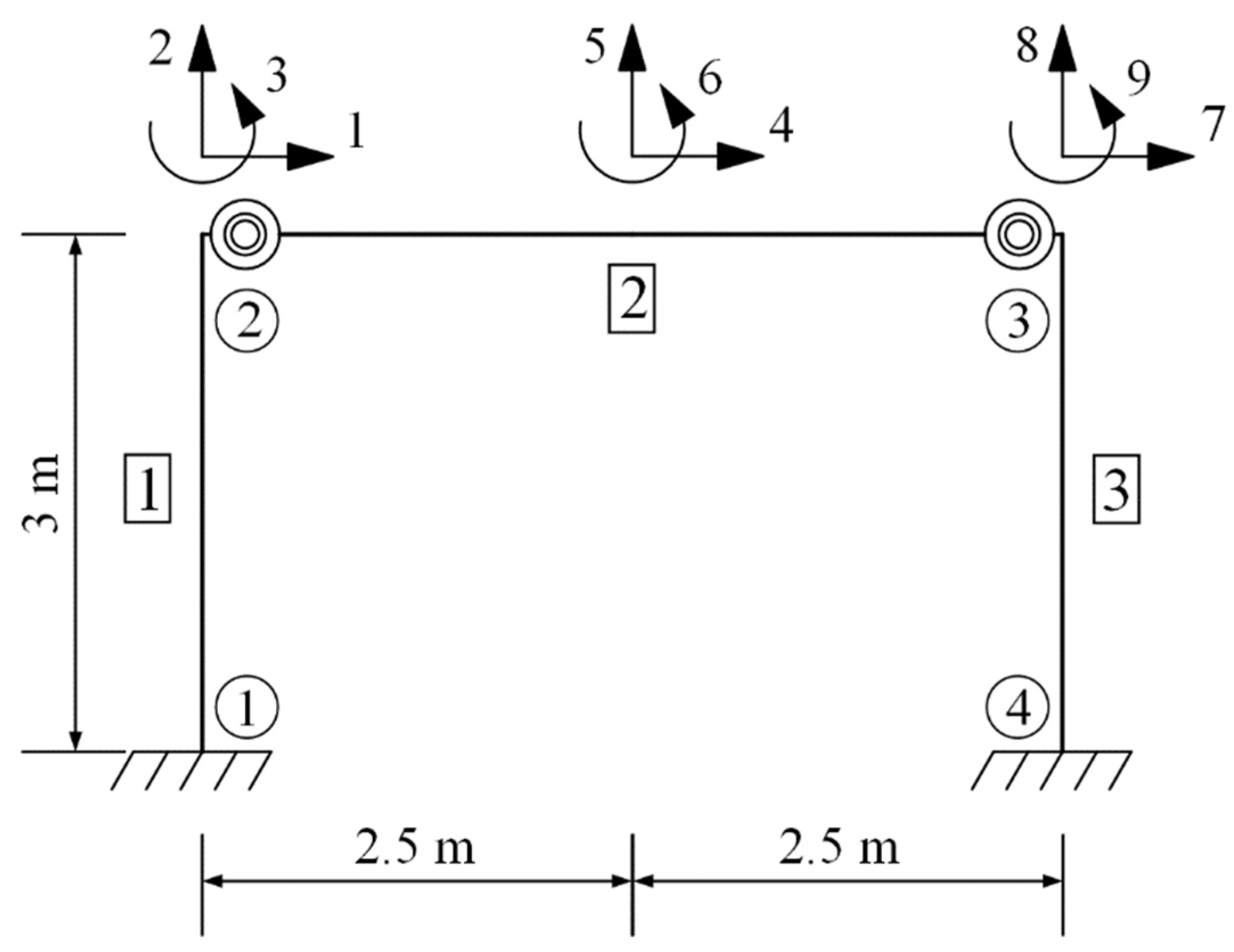
4.2. Parameter Identification for a Rigid Frame Sample

The one-story steel frame example is shown in Figure 4. This frame structure is used to demonstrate the parameter-identification method for the rigid frame using static displacements. The modulus of elasticity is 206 GPa. In “as-built” condition, the frame has cross-sectional area A = 2.25 × 10⁻² m2 and moment of inertia I = 4.21875 × 10⁻⁵ m4. Let us assume that damages exist in members 1–3. The “as-is” cross-sectional areas and moment of inertia of members 1–3 are unknown and need to be determined. Forces of 100 and −100 kN were applied along degrees of freedom 4 and 5 to excite the structure, and the displacements Dm were measured along degrees of freedom 1, 2, 4, 5, 7, and 8 (Figure 4). The “as-is” cross-sectional areas and moment of inertia are presented in Figure 5.
The member stiffness matrix k′ of the frame member is obtained from Equation (7), and Equation (4) is the objective function to identify the damage. In this analysis, the starting points of cross-sectional area variable A and moment of inertia variable I are 1.1 × 10⁻² and 2.1 × 10⁻⁵, respectively. The constraints on A are set between 0 and 2.25 × 10⁻² and those on I are set between 0 and 4.21875 × 10⁻⁵, according to the “as-built” condition. Figure 5 displays the changes in A1, A2, A3, I1, I2, and I3 during the optimization process based on the interior-point method, and Figure 6 shows the variation of the objective function with the number of iterations. After 256 iterations, the final optimal values of A and I were identified, and the results were consistent with those in “as-is” condition.

5. Parameter Identification for a Frame with Semi-Rigid Connections

5.1. Member Stiffness Matrix of Semi-Rigid Frame

The connection type of joint plays a key role in the structural analysis. The analysis and design of steel frames are usually performed under the assumption that the beam-column connections are rigid or pin. In actual engineering, there are some frame structures with rigid connections, which have a certain rotational stiffness owing to damage and other factors. The effect of nodal rotational stiffness on the structural analysis should be considered in the damage identification of frame structures. This study considers frame element connections, including specific nodal rotational stiffness. Semi-rigid connections are modeled by zero-length attaching the rotational springs [28,29] with rotational stiffnesses R1 and R2 at the ends of the member, as shown in Figure 7.
The nodal rotational stiffness represents the degree of rotation capacity between the beam and the column. Parameters β 1 and β 2 are defined as the fixity factors at ends 1 and 2 of the element, respectively, and are related to the corresponding rotational spring stiffnesses R1 and R2, respectively. The member stiffness matrix of a frame element with semi-rigid connections at the ends is given [30,31] in Equation (8). By setting both the parameters β 1 and β 2 equal to 1, Equation (8) becomes equivalent to the member stiffness matrix of the rigid frame element; this means that the nodal rotational stiffnesses are infinite. The unknown parameters, i.e., cross-sectional area Au and moment of inertia Iu, of the damaged member are included in the following matrix. Additionally, the joint damage can be represented as a reduction in the connection rigidity [20,32], and this study used the rotational stiffness Ru to indicate the joint damage condition. The rotational stiffness Ru is also included in the following matrix.
k = E I u L [ A u I u 0 12 L 2 ( n 1 n 7 ) S Y M 0 6 L ( n 2 n 7 ) 4 ( n 3 n 7 ) A u I u 0 0 A u I u 0 12 L 2 ( n 1 n 7 ) 6 L ( n 2 n 7 ) 0 12 L 2 ( n 1 n 7 ) 0 6 L ( n 6 n 7 ) 2 ( n 5 n 7 ) 0 6 L ( n 6 n 7 ) 4 ( n 4 n 7 ) ]
where parameters n are defined using joint fixity factors β 1 and β 2 as follows:
n 1 = β 1 + β 2 + β 1 β 2 ,   n 2 = 2 β 1 + β 1 β 2 ,   n 3 = 3 β 1 , n 4 = 3 β 2 ,   n 5 = 3 β 1 β 2 ,   n 6 = 2 β 2 + β 1 β 2 , n 7 = 4 β 1 β 2
Joint fixity factors β 1 and β 2 can be defined using the nodal rotational stiffness of the end springs as follows:
β 1 = 1 1 + ( 3 E I u / L R u 1 )           β 2 = 1 1 + ( 3 E I u / L R u 2 )
where Ru1 and Ru2 are the unknown nodal rotational spring stiffnesses at different ends of the element, and E and L are the modulus of elasticity and length of the member, respectively.

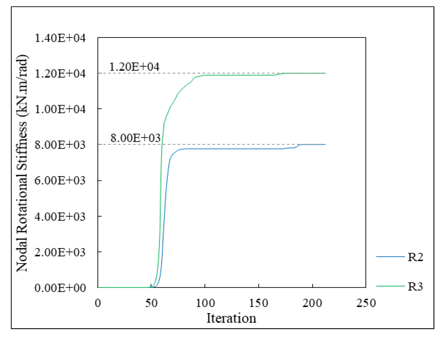
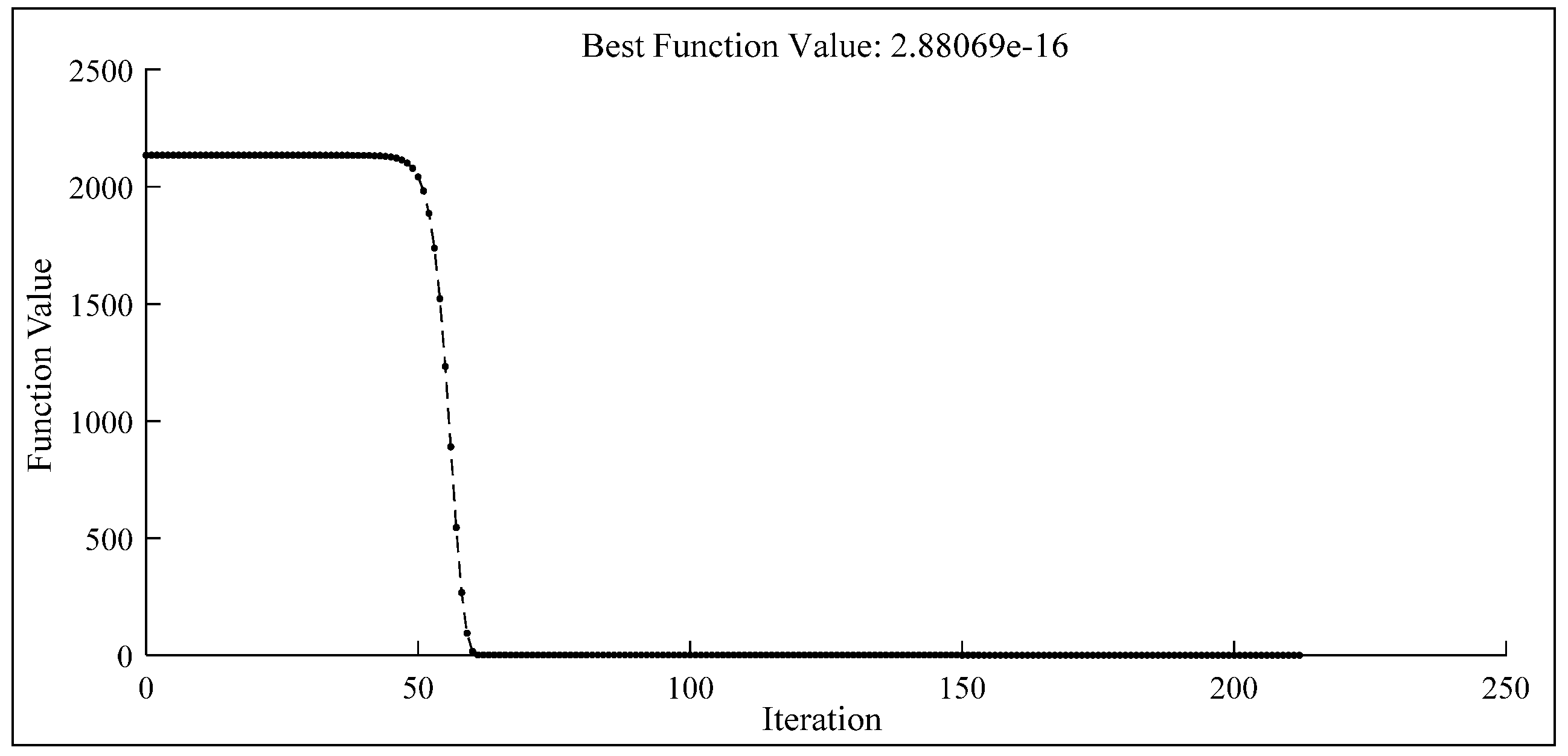
5.2. Nodal Displacement Error Analysis Caused by Nodal Rotational Stiffness Changes

As shown in Figure 8, to compare the effect of different nodal rotational stiffnesses on the nodal displacement of the steel frame structure, steel frame structures with different nodal rotational stiffnesses are simulated, and the nodal displacements of the semi-rigid frame structure with the rigid frame are compared under the same applied forces. Assuming that the nodal rotational stiffness of the semi-rigid frame ranges from 2 × 10³ to 9.8 × 10⁴ kN·m/rad and the nodal rotational stiffness of the rigid frame is infinite, the member stiffness matrix of the frame element with semi-rigid connections at the ends can be obtained by using Equation (8), and the member-global stiffness matrix of the frame can be obtained by using the member stiffness matrix. The nodal displacements of the semi-rigid frame and rigid frame were calculated using Equation (3).
Consequently, the nodal displacements of the semi-rigid frame structure with different nodal rotational stiffnesses are compared with those of the rigid connection. Figure 9 shows the absolute value of the relative error for the nodal displacement with different nodal rotational stiffnesses. The smaller the rotational stiffness, the greater the nodal displacement error. Therefore, in the damage identification of rigid steel frame structures, if the joints are damaged, especially if the damage is serious, it is necessary to consider the impact of the damage on the nodal displacements.

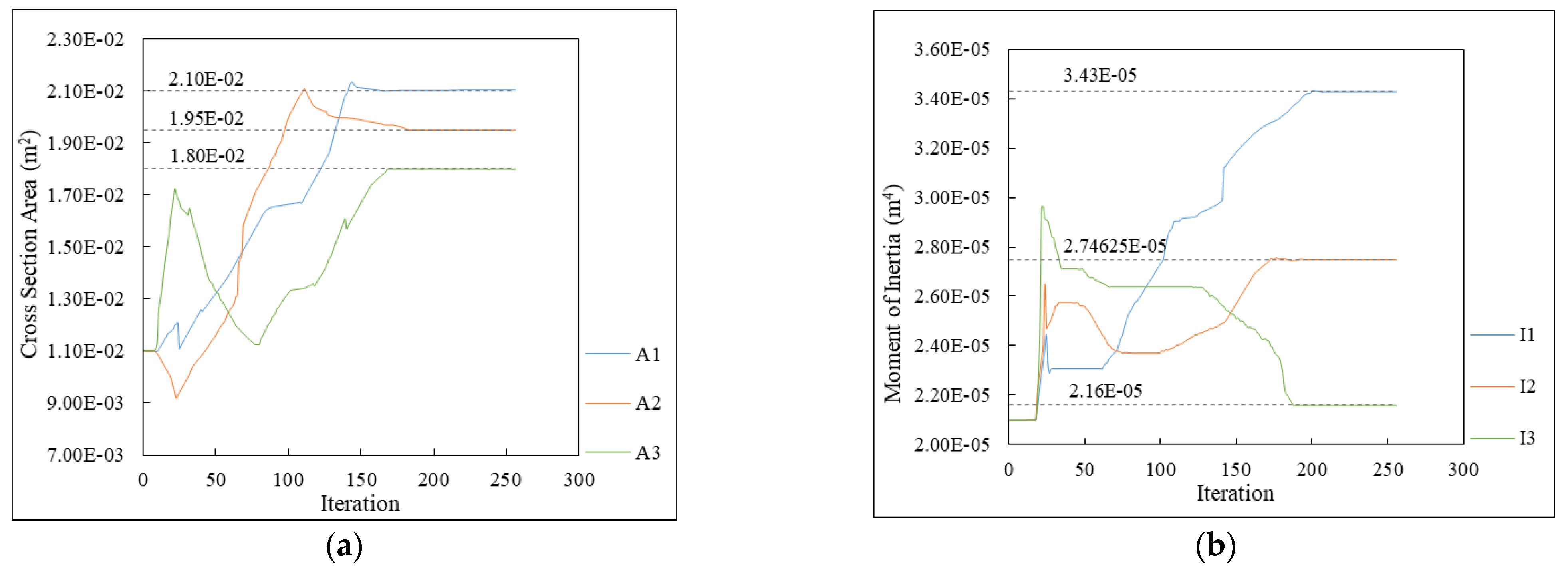
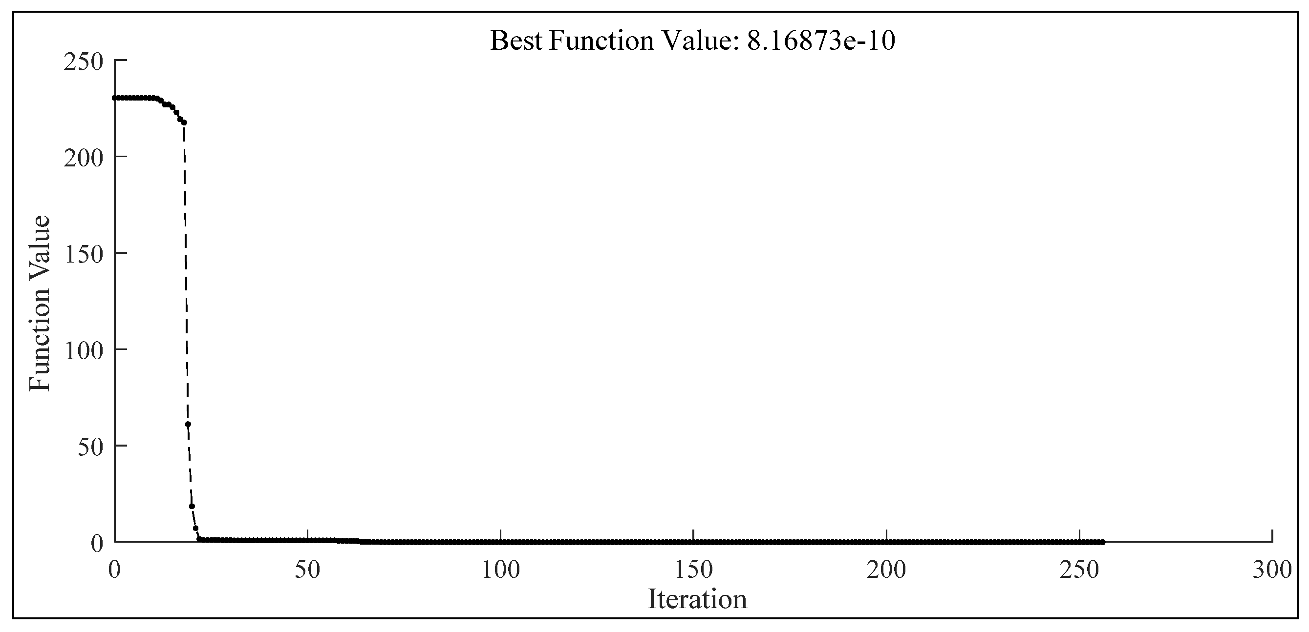
5.3. Parameter Identification for a Frame Sample with Joint Damage

A plane frame structure with a one-story and one-bay configuration is illustrated in Figure 8. This structure is used to demonstrate the joint damage identification method for the steel frame structure. The modulus of elasticity is 206 GPa. All members have the same cross-sectional geometric properties. In “as-built” condition, the frame has cross-sectional areas A = 2.25 × 10⁻² m2 and moment of inertia of I = 4.21875 × 10⁻⁵ m4, and the nodal rotational stiffness of all joints is infinite. Let us assume that damages existing in joints 2 and 3 cause these two joints to transform from rigid connections to semi-rigid connections. The “as-is” nodal rotational stiffnesses of joints 2 and 3 (in the member 2) are 8 × 10³ and 1.2 × 10⁴ kN·m/rad, respectively, which are unknown and need to be determined. Next, let us use applied forces of 100 and −100 kN along degrees of freedom 1 and 5, respectively, and measured displacements along degrees of freedom 1, 2, 4, 5, 7, and 8, respectively.
The member stiffness matrix k′ of the frame member with semi-rigid connections at the ends is obtained from Equation (8), and the damage to joints 2 and 3 can be identified using Equation (4). Simplex method [33] is easy to implement and has been extensively applied to solve optimization problems. The starting point of the nodal rotational stiffness variable R was zero. Figure 10 shows the variation in R2 and R3 with the number of iterations. Figure 11 shows the variation of objective function with the number of iterations. After 212 iterations, the final optimal values of R2 and R3 are 8.000 × 10³ and 1.200 × 10⁴ kN·m/rad, respectively. The optimal values are consistent with the “as-is” values, and the results are all convergence.

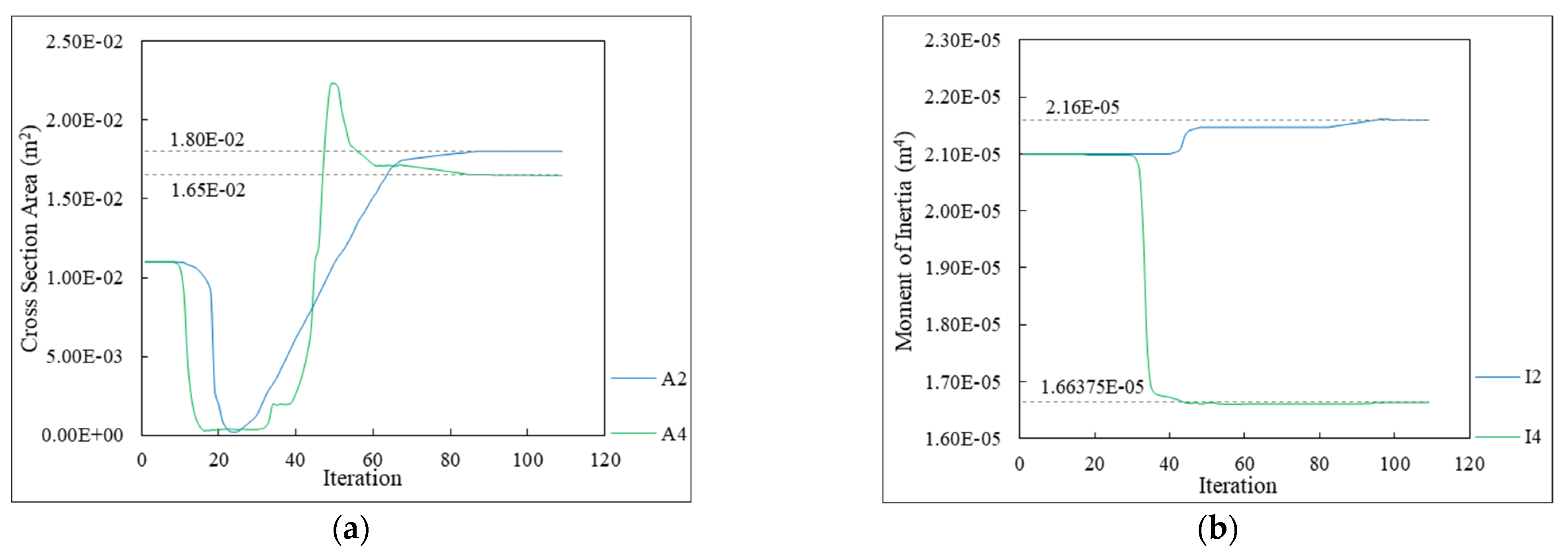
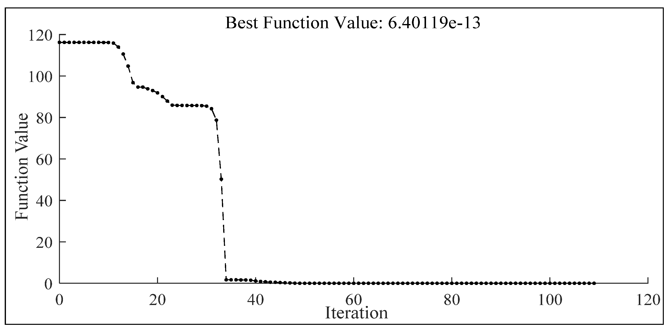
5.4. Parameter Identification for a Frame with Cross-Sectional Damage and Joint Damage

A plane rigid frame with a two-story and one-bay configuration is illustrated in Figure 12. As shown in the figure, the damage identification for a rigid frame with both cross-sectional and joint damage using static displacements is demonstrated. The modulus of elasticity is 206 GPa. All the members have the same cross-sectional geometric properties. In its “as-built” condition, the frame has cross-sectional area A = 2.25 × 10⁻² m2, moment of inertia I = 4.21875 × 10⁻⁵ m4, and the nodal rotational stiffness of all the joints is infinite. Let us assume that damages exist in members 2, 4, and joint 3 (in member 4); these are unknown and need to be determined. To excite the structure, forces of 100 and −100 kN were applied along degrees of freedom 4 and 11, and the damages were identified on the basis of the measured displacements along degrees of freedom 1, 2, 3, 4, 5, 6, 10, 11, and 12. Figure 13 shows the variation of A2, A4, I2, I4, and R3 with the number of iterations, based on the interior-point method. Figure 14 shows the objective function value with respect to the number of iterations. In Figure 13, the dotted lines represent the “as-is” values. After 109 iterations, the final optimal values of A, I, and R were identified, which were consistent with the “as-is” values, and the results are all convergence.

6. Conclusions

In this study, damage identification of rod structures with different connections was performed by using static-displacement measurements. This paper presents a new method to identify damage in rigid frames that have both cross-sectional and joint damage issues. The proposed method can be used to accurately identify the cross-sectional and joint damage in rigid frames, simultaneously. It can also be used to evaluate the rotational stiffness for semi-rigid connections.

Author Contributions

Conceptualization, F.X. and W.Z.; funding acquisition, F.X.; investigation, F.X., W.Z., X.M. and G.S.C.; methodology, F.X. and W.Z.; supervision, F.X.; validation, F.X., W.Z.; writing—original draft, F.X., W.Z. and X.M.; writing—review & editing, F.X., W.Z., X.M. and G.S.C. All authors have read and agreed to the published version of the manuscript.

Funding

This research was funded by the Natural Science Foundation of Jiangsu Province, China, grant number BK20200492.

Conflicts of Interest

The authors declare no conflict of interest.

References

  1. Zapico-Valle, J.L.; García-Diéguez, M.; Alonso-Camblor, R. Nonlinear modal identification of a steel frame. Eng. Struct. 2013, 56, 246–259. [Google Scholar] [CrossRef]
  2. Beskhyroun, S.; Wegner, L.D.; Sparling, B.F. New methodology for the application of vibration-based damage detection techniques. Struct. Control Health Monit. 2012, 19, 632–649. [Google Scholar] [CrossRef]
  3. Nick, H.; Aziminejad, A.; Hosseini, M.H.; Laknejadi, K. Damage identification in steel girder bridges using modal strain energy-based damage index method and artificial neural network. Eng. Fail. Anal. 2020, 119, 105010. [Google Scholar] [CrossRef]
  4. Bandyopadhyay, D.; Saha, S.; Sohail, T. Identification of Parameter of Truss Structure by Limited Static Strain Measurement. Recent Advances in Structural Engineering; Springer: Singapore, 2019; pp. 375–388. [Google Scholar] [CrossRef]
  5. Schommer, S.; Nguyen, V.H.; Maas, S.; Zürbes, A. Model updating for structural health monitoring using static and dynamic measurements. Procedia Eng. 2017, 199, 2146–2153. [Google Scholar] [CrossRef]
  6. Budipriyanto, A. Blind source separation based dynamic parameter identification of a multi-story moment-resisting frame building under seismic ground motions. Procedia Eng. 2013, 54, 299–307. [Google Scholar] [CrossRef]
  7. Bu, H.; Wang, D.; Zhou, P.; Zhu, H. An improved wavelet–Galerkin method for dynamic response reconstruction and parameter identification of shear-type frames. J. Sound Vib. 2018, 419, 140–157. [Google Scholar] [CrossRef]
  8. Sanayei, M.; Onipede, O. Damage assessment of structures using static test data. AIAA J. 1990, 29, 1174–1179. [Google Scholar] [CrossRef]
  9. Terlaje, A.S.; Truman, K.Z. Parameter Identification and Damage Detection Using Structural Optimization and Static Response Data. Adv. Struct. Eng. 2007, 10, 607–621. [Google Scholar] [CrossRef]
  10. Xiao, F.; Hulsey, J.L.; Chen, G.S.; Xiang, Y. Optimal static strain sensor placement for truss bridges. Int. J. Distrib. Sens. Netw. 2017, 13, 1–11. [Google Scholar] [CrossRef]
  11. Xiao, F.; Fan, J.; Chen, G.S.; Hulsey, J.L. Bridge health monitoring and damage identification of truss bridge using strain measurements. Adv. Mech. Eng. 2019, 11, 1–7. [Google Scholar] [CrossRef]
  12. Reyes-Salazar, A.; Haldar, A. Nonlinear Seismic Response of Steel Structures with Semi-Rigid and Compo-site Connections. J. Constr. Steel Res. 1999, 51, 37–59. [Google Scholar] [CrossRef]
  13. Llanes-Tizoc, M.D.; Reyes-Salazar, A.; Ruiz, S.E.; Valenzuela-Beltrán, F.; Bojorquez, E.; Chávez, R. Reliability analysis of steel buildings considering the flexibility of the connections of the GFs. Structures 2020, 27, 2170–2181. [Google Scholar] [CrossRef]
  14. Rigi, A.; JavidSharifi, B.; Hadianfard, M.A.; Yang, T. Study of the seismic behavior of rigid and semi-rigid steel moment-resisting frames. J. Constr. Steel Res. 2021, 186, 106910. [Google Scholar] [CrossRef]
  15. Chen, W.F.; Goto, Y.; Richard-Liew, J.Y. Stability Design of Semi-Rigid Frames; John Wiley and Sons: Hoboken, NJ, USA, 1996. [Google Scholar]
  16. Reyes-Salazar, A.; Sauceda-Pimentel, J.M.; Ruiz, S.E.; Bojórquez, E.; Bojorquez, J. Seismic response and energy dissipation of 3D complex steel buildings considering the influence of interior semi-rigid connections: Low- medium- and high-rise. Bull. Earthq. Eng. 2018, 16, 5557–5590. [Google Scholar] [CrossRef]
  17. de Araújo, F.C.; Ribeiro, I.S.; Machado, R.M. Nonlinear analysis of semi-rigid steel frames having nonprismatic shear-deformable members. Eng. Struct. 2022, 257, 114047. [Google Scholar] [CrossRef]
  18. Yi, J.H.; Yuri, C.B.; Feng, M.Q. Model updating and joint damage assessment for steel frame structures using structural identification techniques. Steel Struct. 2003, 3, 83–94. [Google Scholar]
  19. Altunişik, A.C.; Bayraktar, A.; Sevim, B.; Kartal, M.E.; Adanur, S.; Sevim, B. Finite element model updating of an arch type steel laboratory bridge model using semi-rigid connection. Steel Compos. Struct. 2010, 10, 541–561. [Google Scholar] [CrossRef]
  20. Machavaram, R.; Shankar, K. Joint damage identification using Improved Radial Basis Function (IRBF) networks in frequency and time domain. Appl. Soft Comput. 2013, 13, 3366–3379. [Google Scholar] [CrossRef]
  21. Nanda, B.; Maity, D.; Maiti, D.K. Modal parameter based inverse approach for structural joint damage assessment using unified particle swarm optimization. Appl. Math. Comput. 2014, 242, 407–422. [Google Scholar] [CrossRef]
  22. Pal, J.; Banerjee, S. Identification of semi-rigid joints in steel frame structures using vibration-based technique. Recent Adv. Struct. Eng. 2017, 1, 363–374. [Google Scholar]
  23. Seyedpoor, S.M.; Nopour, M.H. A two-step method for damage identification in moment frame connections using support vector machine and differential evolution algorithm. Appl. Soft Comput. 2020, 88, 106008. [Google Scholar] [CrossRef]
  24. Hou, R.; Beck, J.L.; Zhou, X.; Xia, Y. Structural damage detection of space frame structures with semi-rigid connections. Eng. Struct. 2021, 235, 112029. [Google Scholar] [CrossRef]
  25. Hibbeler, R.C.; Tan, K.H. Structural Analysis; Pearson Prentice Hall: Upper Saddle River, NJ, USA, 2009. [Google Scholar]
  26. Forsgren, A.; Gill, P.E.; Wright, M.H. Interior methods for nonlinear optimization. Soc. Ind. Appl. Math. 2002, 44, 525–597. [Google Scholar] [CrossRef]
  27. Logan, D.L. A First Course in the Finite Element Method; Cengage Learning: Boston, MA, USA, 2012. [Google Scholar]
  28. Xu, L.; Grierson, D.E. Computer-Automated Design of Semirigid Steel Frameworks. J. Struct. Eng. 1993, 119, 1740–1760. [Google Scholar] [CrossRef]
  29. Yun, C.B.; Yi, J.H.; Bahng, E.Y. Joint damage assessment of framed structures using a neural networks technique. Eng. Struct. 2001, 23, 425–435. [Google Scholar] [CrossRef]
  30. McGuire, W.; Gallagher, R.H.; Ziemian, R.D. Matrix Structural Analysis, 2nd ed.; Wiley: Hoboken, NJ, USA, 1999. [Google Scholar]
  31. Simoes, L. Optimization of frames with semi-rigid connections. Comput. Struct. 1996, 60, 531–539. [Google Scholar] [CrossRef]
  32. Lyu, M.; Zhu, X.; Yang, Q. Connection stiffness identification of historic timber buildings using temperature-based sensitivity analysis. Eng. Struct. 2017, 131, 180–191. [Google Scholar] [CrossRef]
  33. Lagarias, J.C.; Reeds, J.A.; Wright, M.H.; Wright, P.E. Convergence Properties of the Nelder-Mead Simplex Method in Low Dimensions. SIAM J. Optim. 1998, 9, 112–147. [Google Scholar] [CrossRef]
Figure 1. Six-member truss.
Applsci 12 05896 g001
Figure 2. Cross-section area as a function of the number of iterations.
Applsci 12 05896 g002
Figure 3. Function value for truss damage identification.
Applsci 12 05896 g003
Figure 4. Three-member rigid frame.
Applsci 12 05896 g004
Figure 5. Cross-sectional area and moment of inertia as a function of the number of iterations. (a) Cross-sectional area; (b) Moment of inertia.
Applsci 12 05896 g005
Figure 6. Function value for rigid frame damage identification.
Applsci 12 05896 g006
Figure 7. Frame element with semi-rigid connection.
Applsci 12 05896 g007
Figure 8. Three-member semi-rigid frame example.
Applsci 12 05896 g008
Figure 9. Nodal displacement error caused by different nodal rotational stiffnesses. (a) Degree of Freedom 1–3; (b) Degree of Freedom 4–6; (c) Degree of Freedom 7–9.
Applsci 12 05896 g009
Figure 10. Nodal rotational stiffness as a function of the number of iterations.
Applsci 12 05896 g010
Figure 11. Function value for semi-rigid frame joint damage identification.
Applsci 12 05896 g011
Figure 12. Six-member frame example.
Applsci 12 05896 g012
Figure 13. Cross-sectional area, moment of inertia, and nodal rotational stiffness as a function of the number of iterations. (a) Cross-sectional area; (b) Moment of inertia; (c) Nodal rotational stiffness.
Applsci 12 05896 g013aApplsci 12 05896 g013b
Figure 14. Function value for a frame with multiple types of damage.
Applsci 12 05896 g014
Publisher’s Note: MDPI stays neutral with regard to jurisdictional claims in published maps and institutional affiliations.

