Article

Adaptive Model Output Following Control for a Networked Thermostat †

1
Zhongyuan-Petersburg Aviation College, Zhongyuan University of Technology, Zhengzhou 450007, China
2
Department of Electronic and Computer Engineering, Ritsumeikan University, Kusatsu 525-8577, Shiga, Japan
*
Authors to whom correspondence should be addressed.
This paper is an extended version of our paper published in Proceeding of the 11th World Congress on Intelligent Control and Automation under the title “Identification Model Based Adaptive Output Following Control for a Networked Micro-reactor”.
Appl. Sci. 2022, 12(12), 6084; https://doi.org/10.3390/app12126084
Submission received: 19 April 2022 / Revised: 1 June 2022 / Accepted: 14 June 2022 / Published: 15 June 2022
(This article belongs to the Special Issue Soft Computing Application to Engineering Design)

Abstract

:
The model of a networked temperature control system is easily affected by its surrounding environment. Because of that, it is hard to identify an accurate model. This paper proposes an adaptive model output following control based on system identification for a networked thermostat system. First, the time-varying system model is built via some thermal laws, whose parameters are identified based on the least-squares method (LSM). The time delay is transferred to deterministic by setting the data buffer. The system stability is ensured by a feedback controller. Meanwhile, an adaptive model output following controller with a command generator tracker (CGT) is designed to adjust the forward control input based on system identification. Finally, the effectiveness of the proposed method is illustrated by simulation and experimental results.

1. Introduction

During the past few decades, networked control systems (NCSs) have been widely applied to industrial control systems with the development of computer and communication science [1,2]. NCSs have some advantages [3,4], such as reduced cost and strong stability. NCSs can be divided into two classes: control of networks [5,6,7] and control through networks [8,9]. Control of networks focuses on improving the quality of network services, such as scheduling, network routing, and network data flow. Control through networks is to obtain the desired performance of control systems that use networks as transmission media. In NCSs, data is not directly transmitted from one node to the destination node, and lots of data are sent through the same network. Due to bandwidth limitations, NCSs have some disadvantages, such as network-induced delay, packet dropouts, and packet disorder [10]. Without considering them, the effectiveness of control systems can not be guaranteed, and NCSs will be unstable.
According to time delay, the research for NCSs can be divided into two classes: stochastic delay methods and deterministic delay methods. In stochastic control methods [11], the time delay is regarded as a random variable. In [12], the variable time delay is smoothed by Hilbert–Huang transform, and a fuzzy controller combining several proportional-integral controllers is designed to ensure system stability. As for packet dropouts it is modeled by Markov chains whose parameters are partly known, and NCSs are regarded as Markov jump linear systems in [13]. What is more, the system stability is guaranteed by a H controller. For packet disordering, linear quadratic regulation is applied to obtain a suboptimal sampling period sequence in [14]. Both packet dropouts and time delay in a networked dc permanent magnet motor system are taken into consideration in [15], and a predictive tracking control algorithm based on the sliding mode is designed to compensate them. In [16], all communication constraints are taken into account together, and a PI controller and a PD controller located at the remote and local sides, respectively. The above controllers are designed according to the statistical properties of communication constraints. Because it is not easy to determine their statistical properties, the designed controllers can not always ensure system stability. Deterministic control is to transfer the time-varying delay from stochastic to deterministic by setting data buffers [17,18]. In [19], data buffers are introduced for both the forward and feedback channels. Based on the command generator tracker (CGT), a model output following control is given for the networked thermal process in [20]. However, the data buffer makes time delay increase and system performance reduces.
Many adaptive control methods [21,22,23] are also developed to ensure system robustness for NCSs with uncertainty or disturbance. For a class of nonlinear NCSs, adaptive fuzzy control is proposed to ensure the boundness of all signals in the closed-loop system in [24]. In [25], measurement uncertainty is considered in NCS models, and the sliding mode control is applied. Meanwhile, some sufficient conditions of the Lyapunov stability are also presented. In [26], NCSs subjected to additive noise are investigated, and a moderate local controller is directly implemented on the plant while a remote controller works through the network. In [27], NCSs with noise are investigated in the delta domain, and optimal control is applied to ensure an upper bound. As to deterministic control, NCSs with uncertainties are taken into consideration in [28,29], and adaptive control based on CGT is proposed. The CGT theory was first proposed for modeling the following problem with known constant parameters [30]. In [28], an adaptive extension is given to consider a little uncertainty.
Because the statistical properties of time delay are not easily obtained, the stochastic control methods are based on their assumptions, and the system stability can not always be ensured. As a result, this paper adopts the buffer strategy, and the time delay becomes deterministic. In this paper, the parameters of a networked thermostat system are time-varying. The adaptive approaches discussed above only consider uncertainty in system models and can not always ensure tracking performance. Motivated by system identification-based methods [31,32], an adaptive model output following the control method based on parameter estimation is given to ensure the system stability and tracking ability for a networked temperature system with time-varying parameters. The time delay becomes deterministic by setting a data buffer. The system stability is guaranteed by a feedback controller. Based on online system identification, a forward adaptive model output following controller is proposed to ensure tracking performance. The main contribution of this paper is the proposal of the adaptive model output following controller for NCSs with time-varying parameters, which can ensure tracking performance.
The remainder part of this paper is organized as follows. Section 2 provides the structure of a networked thermostat system whose model is presented in Section 3. In Section 4, the adaptive model output following control is proposed. The simulation and experimental results are shown in Section 5. The conclusions are provided in Section 6.

2. Networked Thermostat System

As shown in Figure 1 and Figure 2, the networked thermostat system consists of two computers connected to the network, a PCL-812PG board, a PCI-1760U board, a thermostat, a Peltier device, a temperature sensor, and a signal conditioning board. The thermostat temperature is collected and sent to PC1 by PC2. Based on the proposed method, PC1 returns the control outputs over the network. PC2 commands PCI-1760U to produce PWM according to the control output. The Peltier device will cool the thermostat as desired. The signal conditioning board is to amplify the voltage output of the temperature sensor and provides enough power for the Peltier device. Details are shown as follows:
(1)
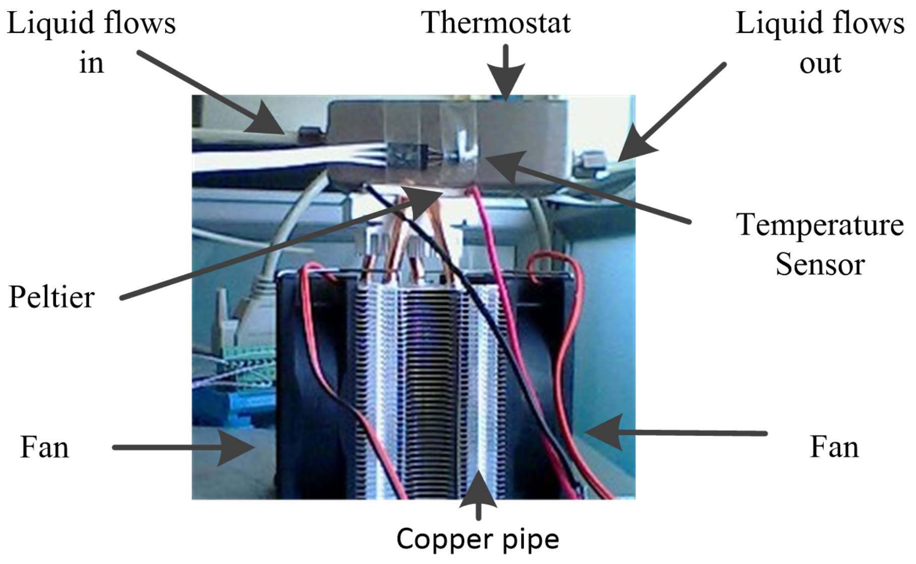
Thermostat: It is a container that ensures the temperature of the liquid flowing out is always the same as desired. While flowing from one side to another side, the liquid will be cooled by the Peltier device.
(2)
Temperature Sensor: LM35 Precision Centigrade Temperature Sensor is used to collect the temperature of the thermostat, whose voltage output increases linearly with the temperature. It is equipped at the side where liquid flows out. Its voltage output range 0–1 V corresponds to the temperature range 0–100 C, and the measurement error is ± 1 4 C.
(3)
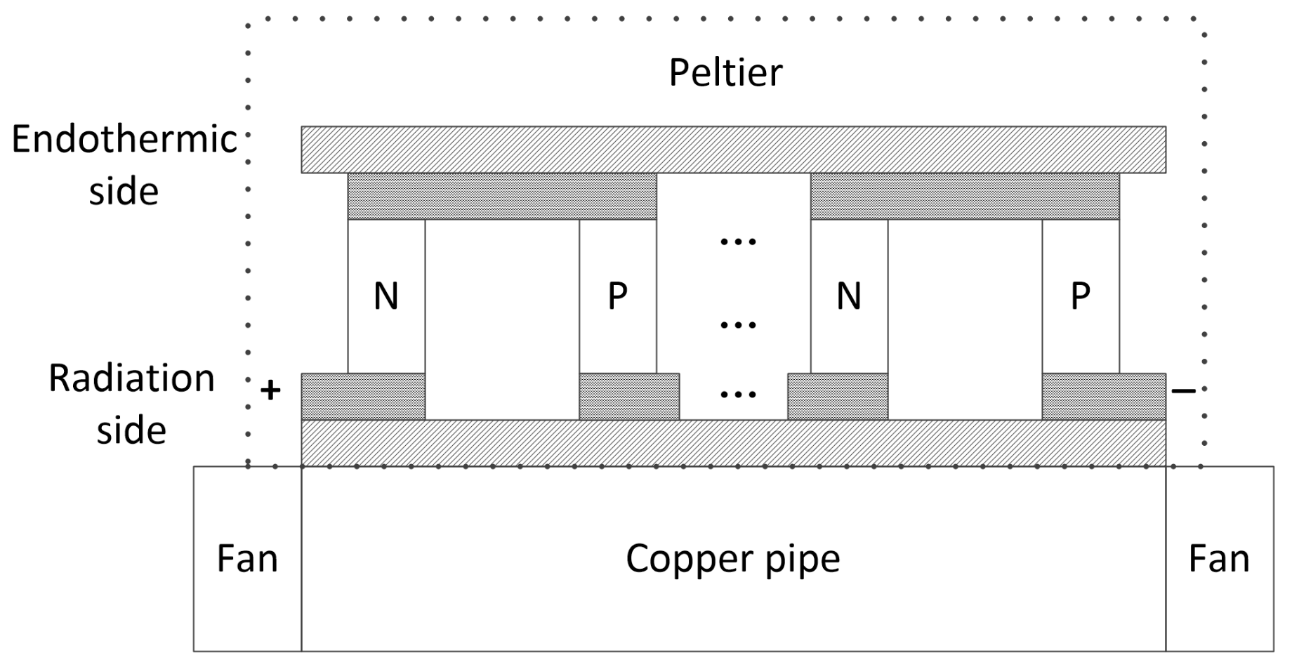
Peltier device: As shown in Figure 3, the Peltier device consists of a Peltier, a copper pipe, and two fans. The working voltage of the Peltier is 12 V. When current flows through the Peltier, the temperature at the endothermic side will decrease, and the other side radiates energy into the air. Its endothermic side is close to the thermostat. To improve the cooling ability, the fans and copper pipe is used to decrease the temperature on the radiation side. In this paper, the Peltier is controlled by pulse width modulation (PWM) produced by the PCI-1760U board.
(4)
PC1: It is used to receive the temperature of the thermostat through the network, run the proposed algorithm, and then return the result through the network.
(5)
PC2: This PC receives data sent by the remote computer PC1 over the network, and outputs the PWM wave to control the PCI-1760U board based on the proposed method. Further, it commands the PCL-812PG board to sample the voltage amplified by the signal conditioning board and send it over the network to the remote computer, PC1.
(6)
Signal conditioning board: In order to improve the precision of temperature, the voltage output of the temperature sensor is amplified from 0–1 to 0–5 V. Because the power provided by the PCI-1760U board is not enough for the Peltier, the PWM amplitude is converted from 5 to 12 V by the signal conditioning board.
(7)
PCL-812PG board: It is inserted in PC2 and used to collect the temperature information from the signal conditioning board by a 12-bit analog-to-digital converter. Its voltage input range is 0–5 V.
(8)
PCI-1760U board: It can produce PWM used to control the thermostat temperature. Its voltage is 5 V and the period is set to 10 ms.
(9)
Network system: It is designed based on a network platform HORB based on the Java programming language. On this platform, a server is designed to manage tasks from local and remote terminals. This platform packets all the communication protocols, primary data processing, and remote function call. The only thing for the two PCs is to provide their IP addresses and tasks to the server at the beginning of the experiments.

3. Modelling

3.1. Peltier Model

In this experiment platform, the Peltier is controlled by PWM. Assuming the PWM duty cycle is denoted by u p , and the current is I c , the electro-thermal amount by the Peltier effect is given by
Q e = S p T e I c u p ,
where S p is the Seebeck coefficient, and T e is the temperature at the endothermic side of the Peltier device. The thermal conduction by the temperature difference between the radiation and endothermic sides is
Q k = K ( T r T e ) ,
where K is the Peltier’s thermal conductivity. The temperature difference ( T r T e ) can be approximated by [33]
T r T e = k 1 I c u p + k 2 e k 3 t k 4 e k 5 t ,
where k 1 k 5 are constant. The Joule heat by the current is written as
Q j = 1 2 R p I c 2 u p ,
where R p is Peltier’s resistance. The endothermic heat Q p consists of the above three parts [34]:
Q p = Q e Q k Q j = ( S p T 1 I c 1 2 R p I c 2 ) u p K ( k 1 I c u p + k 2 e k 3 t k 4 e k 5 t ) = ( S p T 1 I c 1 2 R p I c 2 + K k 1 I c ) u p + K ( k 2 e k 3 t k 4 e k 5 t ) .

3.2. Thermostat Model

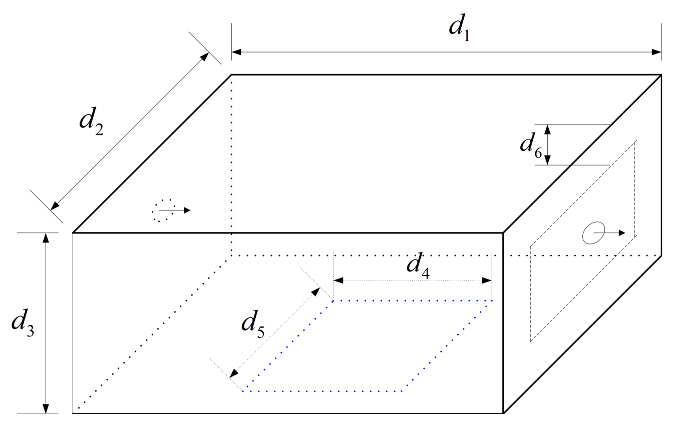
The configuration of the thermostat process is shown in Figure 4 and Table 1. Liquid flows from one side to the other side. Assume heat is conducted from top to bottom, the heat conduction Q c , based on Fourier’s law of heat conduction, is computed as
Q c = λ ( T 0 T ( t ) ) d 6 ( d 2 d 1 d 4 + 2 d 3 + d 1 d 3 + 2 d 2 ) ,
where T 0 and T ( t ) are the initial temperature and current temperature, respectively. The constant λ is the thermal conductivity of the thermostat. As the temperature of the thermostat drops, the released heat is given by
Q d = d ( T 0 T ( x ) ) m a c a d t ,
where m a is the quality of the thermostat and c a is its specific heat coefficient. Based on Newton’s law of cooling, the convective heat from the thermostat to the air is
Q c = α ( T 0 T ( x ) ) d 4 ( d 2 d 5 ) .
The released heat of the temperature drop from the liquid is given by
Q l = d ( T 0 T ( x ) ) m l c l d t ,
where m l is the quality of liquid and c l is its specific heat coefficient. The heat released by the temperature drop from the air temperature in the thermostat is
Q a = d ( T 0 T ( x ) ) V a c v d t ,
where V a is the volume of the air in the thermostat and c v is the specific heat coefficient of air. According to the conservation of energy, the thermostat can be modeled as
( m a c a m l c l V a c v ) d ( T 0 T ( x ) ) d t = λ ( T 0 T ( x ) ) d 6 ( d 2 d 1 d 4 + 2 d 3 + d 1 d 3 + 2 d 2 ) α ( T 0 T ( x ) ) d 4 ( d 2 d 5 ) + Q p .
Define y ( t ) = T 0 T ( x ) , and Equation (11) can be rewritten as
a 0 d y ( t ) d t + a 1 y ( t ) = ( S p T 1 I c 1 2 R p I c 2 + K k 1 I c ) u p + K ( k 2 e k 3 t k 4 e k 5 t ) ,
where
a 0 = m a c a m l c l V a c v ,
a 1 = λ d 6 ( d 2 d 1 d 4 + 2 d 3 + d 1 d 3 + 2 d 2 ) + α d 4 ( d 2 d 5 ) .
Because the mass of liquid m a and the volume of air in the thermostat are not constant, a 0 varies with time. Define one time-varying variable β , which satisfies
β u p = K ( k 2 e k 3 t k 4 e k 5 t ) .
Then the model becomes
a 0 d y ( t ) d t + a 1 y ( t ) = b 1 u p ,
where b 1 is also time-varying and given by
b 1 = S p T 1 I c 1 2 R p I c 2 + K k 1 I c + β .
According to Laplace transform, the transfer function of the equation above can be represented by
G ( s ) = b 1 a 0 s + a 1 .

3.3. Networked System Model

The total time delay in both the forward and feedback network channels of the closeloop networked system is shown in Figure 5. It is shown that the delays are about 19 s in this network system. In our program, the time delay T d is set to 19 by setting a data buffer. As a result, the networked system model with deterministic delay can be modeled by
G p ( s ) = G ( s ) * e T d S .

4. Adaptive Model Output Following Control

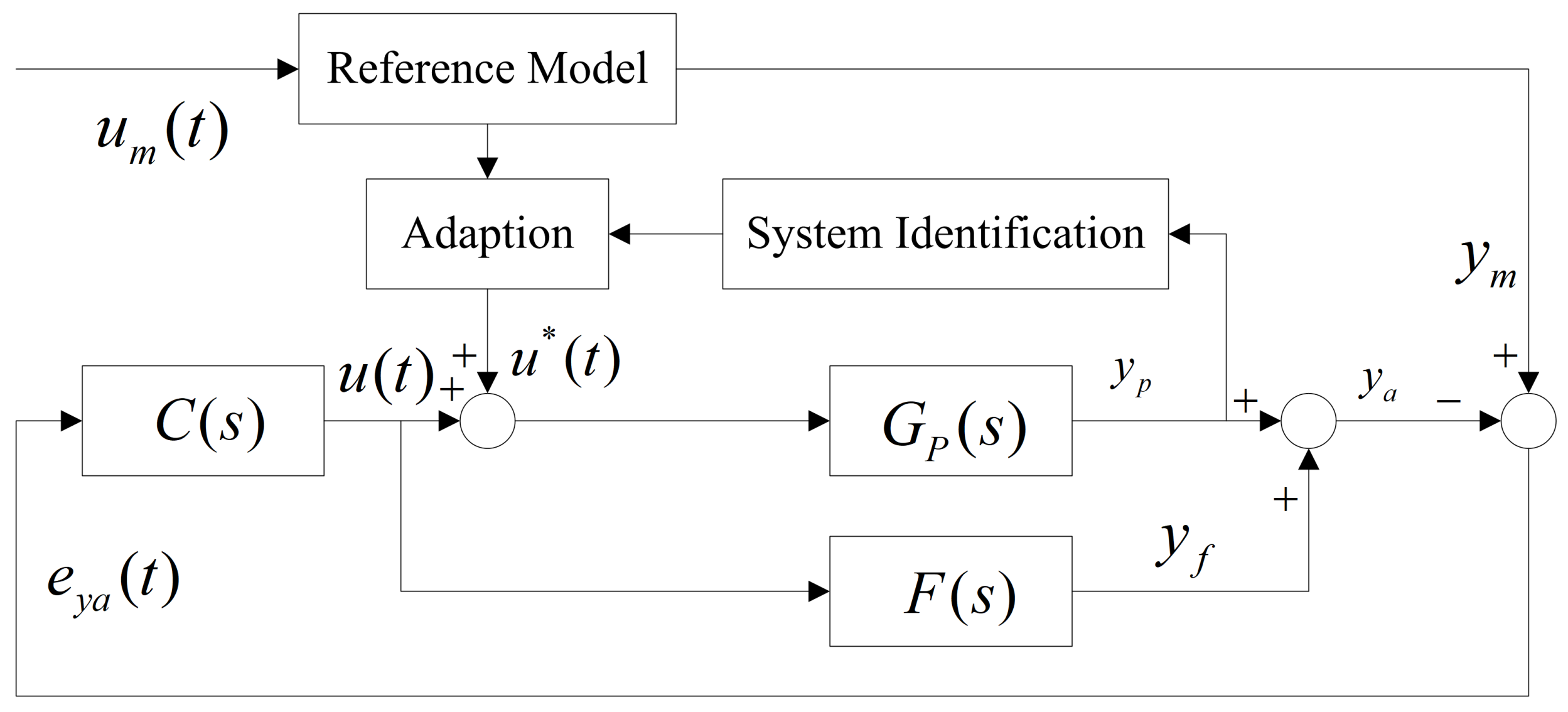
Figure 6 shows the proposed adaptive model output following control for the networked thermostat system, where u ( t ) and u * ( t ) are the feedback and forward inputs, respectively. The compensator F ( s ) is designed to transform an augmented plant into an almost strictly positive real (ASPR). The feedback controller C ( s ) is to ensure system stability. The adaption part is based on CGT and adjusted u ( t ) based on system identification.

4.1. Compensator

Because of time delay, the networked system model G p ( s ) is non-ASPR, and a compensator can be designed to augment G p ( s ) such that the augmented plant can satisfy ASPR [35]. When the time delay is described by the first, second, or higher-order lag term, the NCS model G p ( s ) can be approximated by:
G p ( s ) G p * ( s ) = G ( s ) * 1 ( 1 + T d n s ) n , n = 1 , .
It can also be written as
G p ( s ) = e 0 s n + e 1 s n 1 + e n f 0 s n + f 1 s n 1 + + f n .
The compensator F ( s ) can be designed as following [35]:
F ( s ) = s G ( s ) s + n T d i = 1 n F 1 i ( s ) + j = 1 m 2 m 1 1 δ j F 2 j ( s ) ,
F 1 i ( s ) = ( T d s + n T d ) i 1 , i = 1 , , n ,
F 2 j ( s ) = β j n j ( s ) d j ( s ) , j = 1 , , m 2 m 1 1 ,
where δ is a small positive constant, d j ( s ) is a monic stable polynomial of any order n d j ( m 2 m 1 j ) , and n j ( s ) is a monic stable polynomial of any order m n j ( = n d j ( m 2 m 1 j ) ) . The parameter β is chosen such that the following polynomial is the Hurwitz polynomial
r ( s ) = β m 2 m 1 1 s m 2 m 1 1 + + β 1 s + β 0 .

4.2. Robust Feedback Controller

Given the compensator, the plant is augmented as
G a ( s ) = G p ( s ) + F ( s ) .
The feedback controller C ( s ) is designed as a constant k e . Define the following functions:
G ^ ( s ) = G p * ( s ) + F ( s ) ,
G ( s ) = G p ( s ) G p * ( s ) ,
G a ( s ) = G ( s ) + G ^ ( s ) ,
and a sufficient condition for the stability of closed-loop control is given by
G ( j ω ) < 1 k e + G ( j ω ) + i = 1 m 2 m 1 1 δ i F 2 i ( j ω ) , ω [ 0 , ) .

4.3. System Identification

Normally, system parameters are identified in discrete space. Assume the discrete model of G ( s ) is described by
y ( k ) + a 0 y ( k 1 ) = b 1 u p ( k ) ,
where the time interval is T d . Because of the deterministic time delay, the discrete model of G p ( s ) is given by
y p ( k + 1 ) + a 0 y p ( k ) = b 1 u p ( k ) ,
and y ( k 1 ) = y p ( k ) . Even though the temperature data are received with a time delay, the above two equations show that the parameters of G ( s ) in discrete space can be estimated directly. There are various identification methods for linear or nonlinear systems. Because of the simplicity of the above system model, LMS is applied to estimate the parameters a 0 and b 1 online in this paper. Based on the Runge–Kutta method, the parameters in continuous state space can be obtained by
a 0 = T d a 0 ,
a 1 = 1 + a 0 ,
b 1 = b 1 .

4.4. Adaptation

The adaptive controller is based on CGT theory. Assume that the reference model is denoted by G m ( s ) and expressed as:
G m ( s ) = K m T m s + 1 ,
and the state-space representation of G m ( s ) is described as follows:
x ˙ m ( t ) = A m x m ( t ) + B m u m ( t ) = y m ( t ) T m + K m T m u m ( t ) y m ( t ) = C m x m ( t ) + D m u m ( t ) = y m ( t ) ,
where x m ( t ) can be represented by
x m ( t ) = y m ( t ) = K m u m ( t ) T m y m ( t ) .
Assuming the state space of G p ( s ) is represented by
x ˙ p ( t ) = A x p ( t ) + B u p ( t ) y p ( t ) = C x p ( t ) + D u p ( t ) ,
the tracking controller is given by [30]
u * ( t ) = S 21 x m ( t ) + S 22 u m ( t ) + S 3 ( t ) ,
where
S 11 = Ω 11 S 11 A m + Ω 12 C m T , S 12 = Ω 11 S 11 B m , S 21 = Ω 11 S 11 A m + Ω 22 C m T , S 22 = Ω 11 S 11 B m , Ω 11 v ˙ ( t ) = v ( t ) S 12 u ˙ m ,
S 3 = Ω 21 v ( t )
A B C T D Ω 11 Ω 12 Ω 21 Ω 22 = I .
Theorem 1.
When the NCS model and the first-order reference model are represented by Equations (21) and (36), respectively, the tracking performance can be ensured by the following forward controller:
u * ( t ) = S 1 x m ( t ) + S 2 y ˙ m ( t ) + S 3 ( t ) ,
where S 1 and S 2 are computed by
S 1 = K m f n e n , S 2 = ( Ω 21 S 11 T m f n e n ) T m .
The first term, S 1 x m ( t ) in Equation (44), guarantees the steady steady-state error, and the other two ensure the tracking performance.
Proof of Theorem 1.
Based on Equation (21), the state-space function of the NCS model G p ( s ) can be given by
x ˙ p ( t ) = 0 1 0 0 0 0 1 0 0 0 0 0 1 f n f n 1 f n 2 f 1 x p ( t ) + γ 1 γ 2 γ n 1 γ n u p ( t )
y p ( t ) = [ 1 , 0 , , 0 , 0 ] x p ( t ) + γ 0 u p ( t ) ,
where [ γ 0 , γ 1 , γ 2 , , γ n ] T is the solution of the following matrix equation
1 0 0 0 f 1 1 0 0 f 2 f 1 1 0 f n f n 1 f n 2 1 γ 0 γ 1 γ 2 γ n = e 0 e 1 e 2 e n .
Based on the equation above, the following equation can be obtained:
γ n + f 1 γ n 1 + + f n γ 0 = e n .
Then A B C T D can be written as
A B C T D = 0 1 0 0 γ 1 0 0 1 0 γ 2 0 0 0 1 γ n 1 f n f n 1 f n 2 f 1 γ n 1 0 0 0 γ 0 .
Its value can be computed by
A B C T D = ( 1 ) n ( γ n + f 1 γ n 1 + + f n γ 0 ) = ( 1 ) n e n .
The algebraic complement M ( n + 1 ) ( n + 1 ) of the element at n + 1 row and n + 1 column in A B C T D is shown as following
M ( n + 1 ) ( n + 1 ) = 0 1 0 0 0 0 1 0 0 0 0 1 f n f n 1 f n 2 f 1 = ( 1 ) n f n .
The variable Ω 22 can be given by
Ω 22 = M ( n + 1 ) ( n + 1 ) A B C T D = f n e n .
Combining Equations (42), (43), and (45), Equation (44) can be obtained. □

5. Simulation and Experimental Results

5.1. Simulation Results

As stated in Section 2, the system parameters are time-varying. In order to illustrate how the designed controller works when system parameters change, the model G ( s ) is assumed to change as follows:
G ( s ) = 0.13 160 s + 1 , 0   s < t < 2622   s 0.15 162 s + 1 , 2622   s t < 4370   s .
The above two functions are two possible models for G ( S ) , which will be illustrated in the experimental parameter estimation. The parameters a 0 , a 1 , and b 1 of model G ( s ) are identified by LSM, as described in Section 4.3. The time-varying delay becomes deterministic by setting a data buffer in the experimental platform, while T d is set to 19 directly in the simulation for convenience. Let n = 3 , the NCS model can be approximated by
G p * ( s ) e 4 f 0 s 4 + f 1 s 3 + f 2 s 2 + f 3 s 1 + f 4 .
where
f 0 = 1 27 a 0 T d 3 , f 1 = 1 3 a 0 T d 2 + 1 27 a 1 T d 3 f 2 = a 0 T d + 1 3 a 1 T d 2 , f 3 = a 0 + a 1 T d f 4 = a 1 , e 4 = b 1 .
The compensator terms F 2 i ( s ) can be constructed as follows:
F 21 ( s ) = β 1 n 1 ( s ) d 1 ( s ) F 22 ( s ) = β 2 n 2 ( s ) d 2 ( s ) n 1 ( s ) = n 2 ( s ) = s 2 d 1 ( s ) = ( s + 2 ) 4 , d 2 ( s ) = ( s + 2 ) 3
where β 2 = 1 , β 1 = 0.6 , and β 0 = 0.09 . The compensator is given by
F ( s ) = s G ( s ) s + 3 T d i = 1 3 ( T d s + 3 T d ) i 1 + 0.6 s 2 ( s + 2 ) 4 + s 2 ( s + 2 ) 3
where G ( s ) are time-varying with identified parameters rather than Equation (54). The reference model is given by
G m ( s ) = 1 60 s + 1 .
The forward control input u * is computed by
u * ( t ) = f 4 e 4 u m ( t ) + ( f 0 e 4 T m 3 + f 1 e 4 T m 2 f 2 e 4 T m + f 3 e 4 f 4 T m e 4 ) y ˙ m ( t ) .
The reference input u m ( t ) is set to 2.5 and K e = 1 .
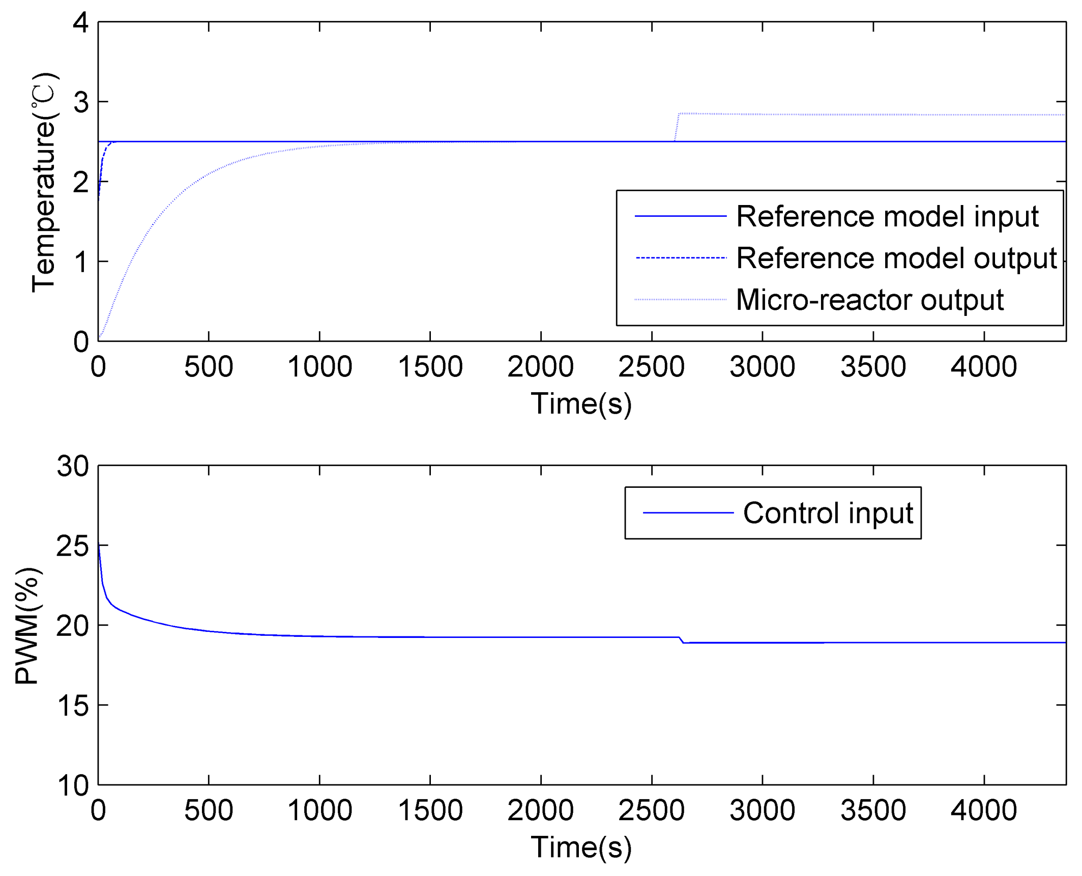
The simulation result of the CGT-based method [20] is shown in Figure 7. The settling time is about 1000 s. Before system parameters change, the system output follows the reference output, and the steady-state error is 0. After the system model changes, the control output also changes. However, the steady-state error does not decrease.
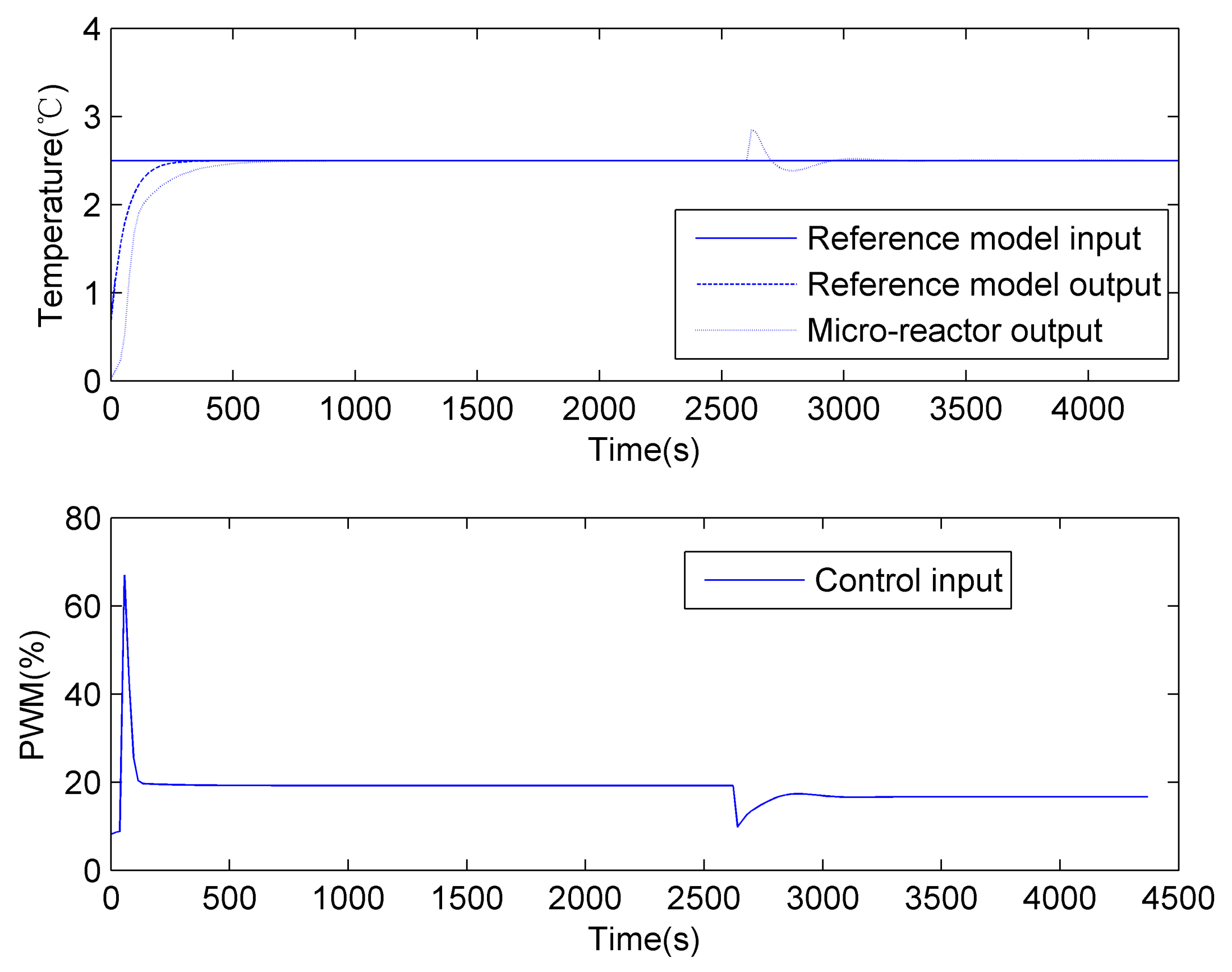
The results of the proposed method are shown in Figure 8 and Figure 9. The settling time is about 500 s, and the steady-state error is 0. The parameter estimation converges after several time intervals. After system parameters change, the maximum error is 0.3 C, and the system parameters are estimated correctly by the LMS method in 400 s. Meanwhile, the steady-state error becomes 0.
When parameters a 0 and b 1 change as follows
a 0 = 162 + 5 cos ( π t 1520 ) ,
b 1 = 0.15 + 0.05 sin ( π t 1900 ) ,
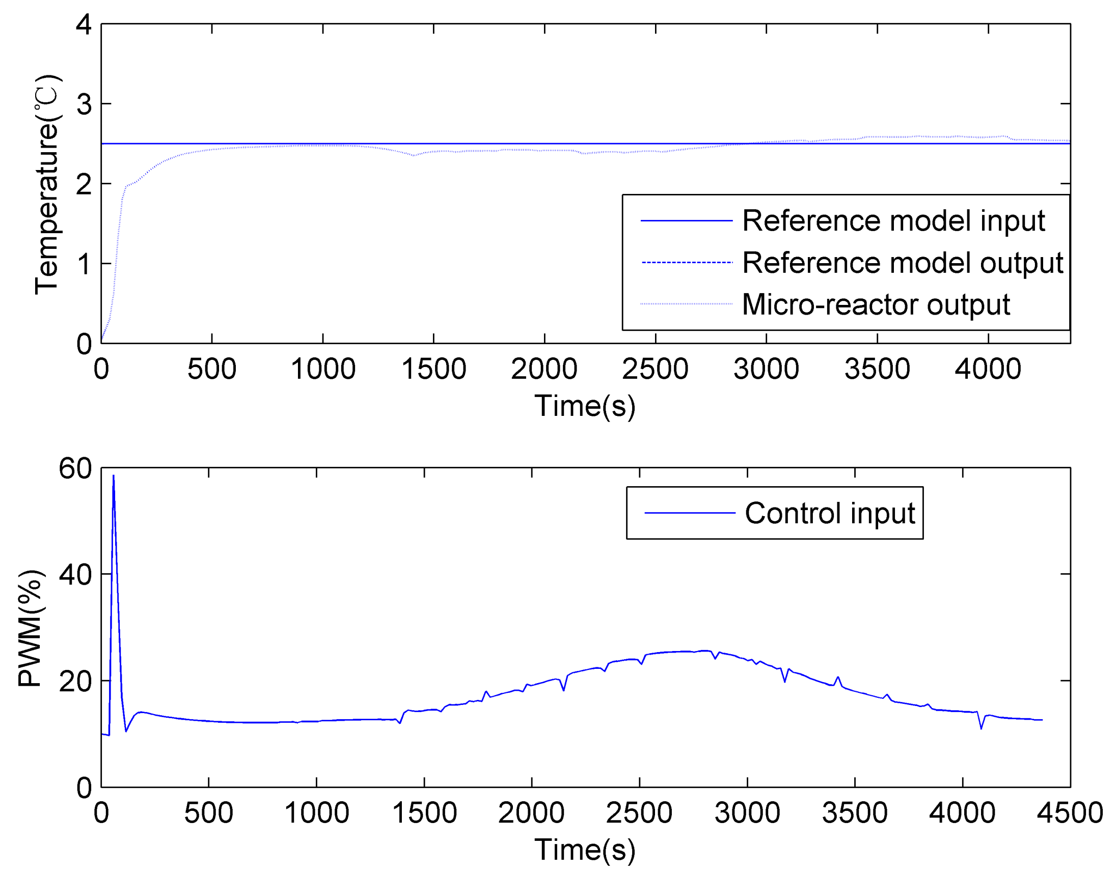
the simulation results and parameter estimation are shown in Figure 10 and Figure 11. At 500 s, the abstract temperature error is 0.08 C, and the steady-state error is 0.15 C. These results show that the proposed method ensures system stability for NCSs with time-varying parameters.

5.2. Experimental Results

In experiments, the feedback gain k e is set to 0.1, and the reference model does not change. The reference input varies as follows:
u m ( t ) = 4 , 0 s < t < 1520 s 4 + 2 sin ( π t 1520 π 1140 ) , 1520 s t < 3800 s 3 , 3800 s t < 6650 s .
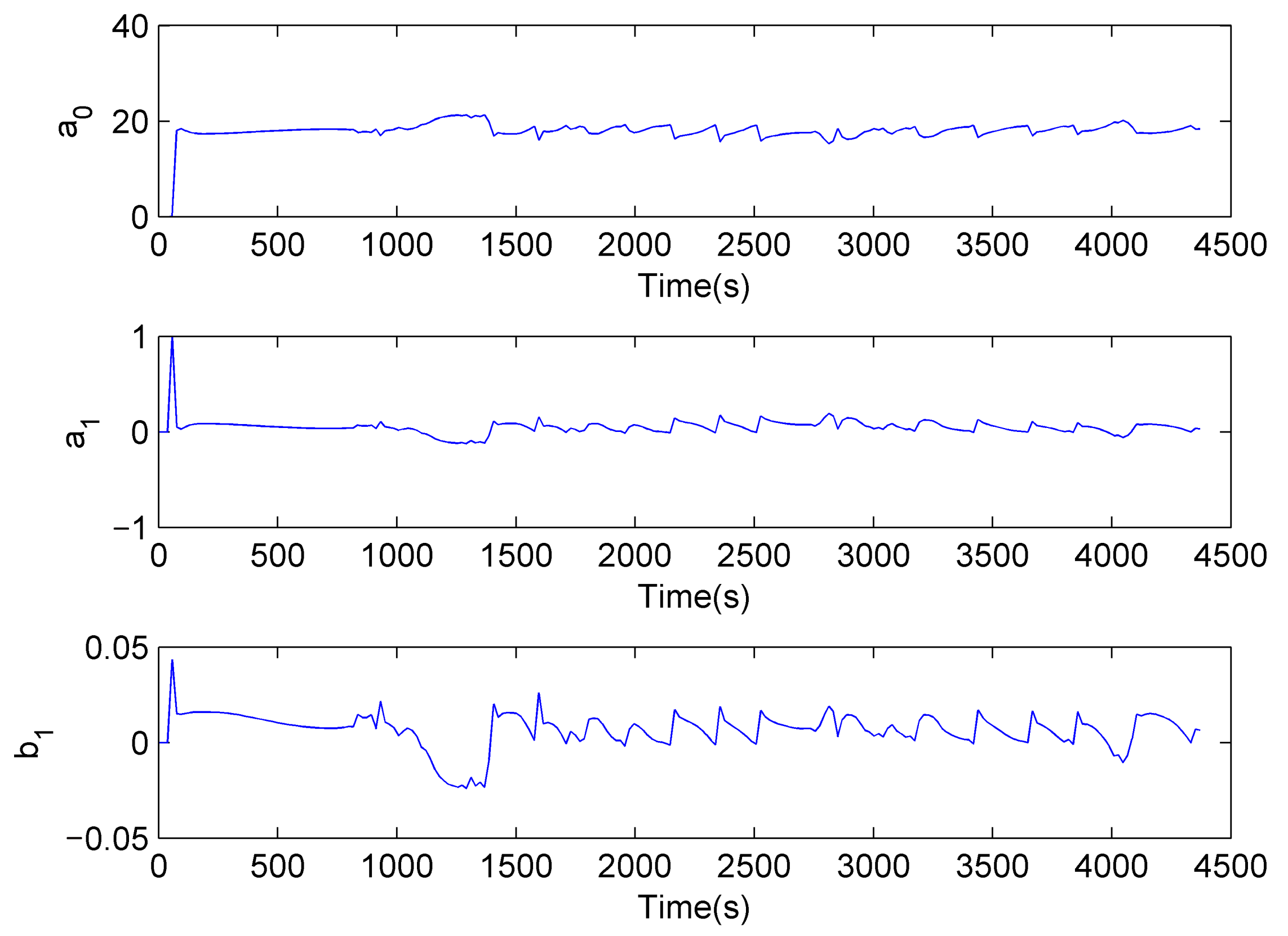
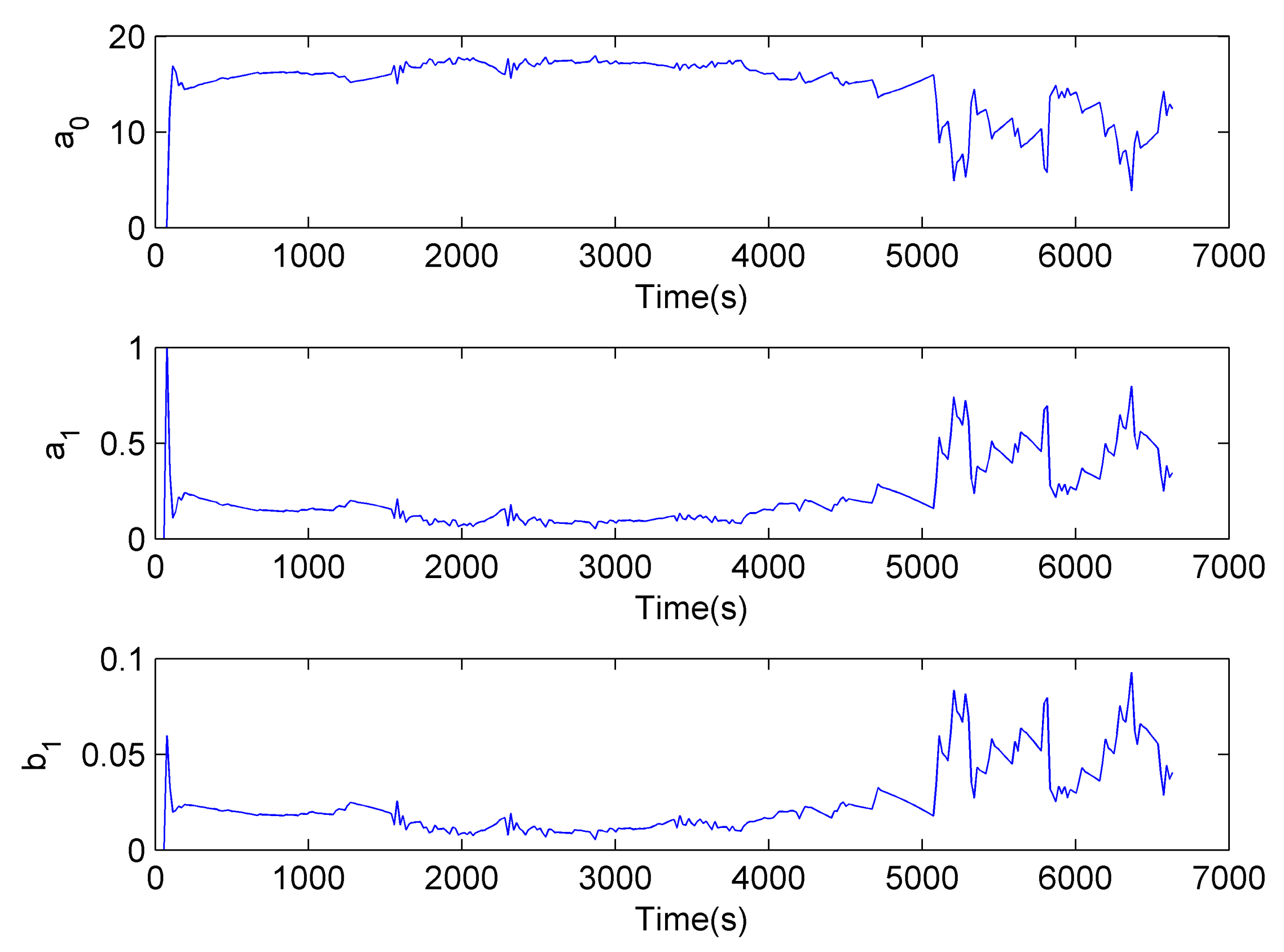
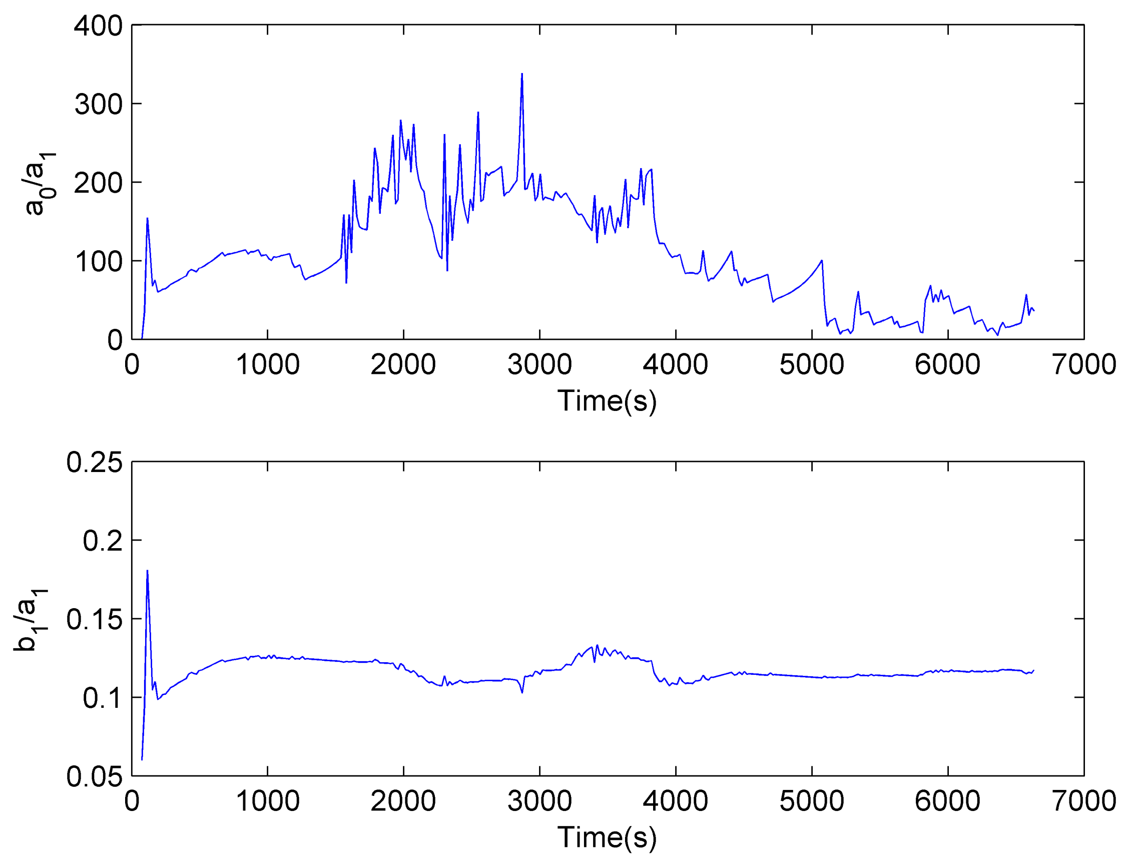
Figure 12 shows the parameter estimation results. Let a 1 = 1 ; the other two parameters are shown in Figure 13. They certify that the NCS model is time-varying. When the reference input does not change, the estimated parameters change slowly. While u m ( t ) changes as the sine function, the parameter estimation process can not converge.
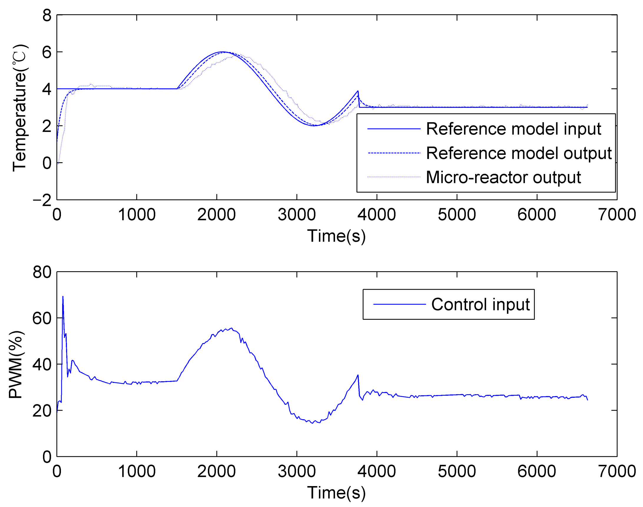
The tracking performance is shown in Figure 14. In the beginning, parameter estimation does not converge, and the maximum abstract error is 1.88 C. From 300 to 1520 s, the system output becomes steady, and the steady-state error is 0.2 C. When the reference input changes as the sine function from 1520 to 3800 s, the maximum tracking error is 0.8 C. In the last period, the steady-state error is 0.16 C. The experimental results show that the proposed methods can ensure the tracking performance for time-varying NCSs.
When the reference input changes as follows:
u m ( t ) = 5 , 0 s < t < 1140 s 4 + 2 sin ( π t 1140 π 1140 ) , 1140 s t < 3420 s 2 , 3420 s t < 4408 s ,
the tracking performance is shown in Figure 15. Compared with the previous experiment results, the system performance is similar to that. The maximum abstract error is 3.08 C in the beginning, while the steady-state error is 0.23 C from 400 to 1140 s. When the reference input varies from 1140 to 3420 s, the maximum tracking error is 0.83 C. In the last period, the steady-state error is 0.08 C.

6. Conclusions

In this paper, an adaptive model output following the control method is proposed for a networked temperature control system with time-varying parameters. The time delay is set to 19 s by the data buffer. To apply CGT theory, a compensator is designed. The feedback controller is used to ensure system stability. The adaptive model output following control is designed to adjust the control output according to system parameter estimation. The experimental results show that the maximum steady-state error is 0.16 C. The maximum tracking error for time-varying reference input is 0.8 C. The effectiveness of the proposed method is confirmed by the simulation and experimental results.

Author Contributions

Conceptualization, H.L. and S.W.; Data curation, Y.J. and P.L.; Formal analysis, R.Z. and X.Y.; Funding acquisition, H.L., P.L. and J.Y.; Investigation, Y.J. and X.Y.; Methodology, H.L. and S.W.; Project administration, J.Y.; Resources, Y.J.; Software, Y.J.; Validation, H.L., Y.J. and P.L.; Writing—original draft, H.L.; Writing—review and editing, J.Y., R.Z. and S.W. All authors have read and agreed to the published version of the manuscript.

Funding

This work was supported by the Scientific and Technological Project in Henan Province (grant numbers 222102210019, 222102520024 and 212102210080).

Conflicts of Interest

The authors declare no conflict of interest.

References

  1. Zhang, X.M.; Han, Q.L.; Ge, X.; Ding, L. Resilient control design based on a sampled-data model for a class of networked control systems under denial-of-service attacks. IEEE Trans. Cybern. 2019, 50, 3616–3626. [Google Scholar] [CrossRef] [PubMed]
  2. Peng, C.; Sun, H. Switching-like event-triggered control for networked control systems under malicious denial of service attacks. IEEE Trans. Autom. Control 2020, 65, 3943–3949. [Google Scholar] [CrossRef]
  3. Zhang, X.M.; Han, Q.L.; Ge, X.; Ding, D.; Ding, L.; Yue, D.; Peng, C. Networked control systems: A survey of trends and techniques. IEEE/CAA J. Autom. Sin. 2020, 7, 1–17. [Google Scholar] [CrossRef]
  4. Lin, H.; Su, H.; Chen, M.Z.; Shu, Z.; Lu, R.; Wu, Z.G. On stability and convergence of optimal estimation for networked control systems with dual packet losses without acknowledgment. Automatica 2018, 90, 81–90. [Google Scholar] [CrossRef] [Green Version]
  5. Feng, S.; Cetinkaya, A.; Ishii, H.; Tesi, P.; De Persis, C. Networked control under DoS attacks: Tradeoffs between resilience and data rate. IEEE Trans. Autom. Control 2020, 66, 460–467. [Google Scholar] [CrossRef]
  6. Ferrari, P.; Sisinni, E.; Bellagente, P.; Rinaldi, S.; Pasetti, M.; de Sá, A.O.; Machado, R.C.; Carmo, L.F.d.C.; Casimiro, A. Model-based stealth attack to networked control system based on real-time Ethernet. IEEE Trans. Ind. Electron. 2020, 68, 7672–7683. [Google Scholar] [CrossRef]
  7. Cao, J.; Ding, D.; Liu, J.; Tian, E.; Hu, S.; Xie, X. Hybrid-triggered-based security controller design for networked control system under multiple cyber attacks. Inf. Sci. 2021, 548, 69–84. [Google Scholar] [CrossRef]
  8. Mahmoud, M.S.; Hamdan, M.M. Fundamental issues in networked control systems. IEEE/CAA J. Autom. Sin. 2018, 5, 902–922. [Google Scholar] [CrossRef]
  9. Li, M.; Chen, Y. Challenging research for networked control systems: A survey. Trans. Inst. Meas. Control 2019, 41, 2400–2418. [Google Scholar] [CrossRef]
  10. Hu, J.; Zhang, H.; Liu, H.; Yu, X. A survey on sliding mode control for networked control systems. Int. J. Syst. Sci. 2021, 52, 1129–1147. [Google Scholar] [CrossRef]
  11. Tian, E.; Wang, K.; Zhao, X.; Shen, S.; Liu, J. An improved memory-event-triggered control for networked control systems. J. Frankl. Inst. 2019, 356, 7210–7223. [Google Scholar] [CrossRef]
  12. Precup, R.E.; Preitl, S.; Petriu, E.; Bojan-Dragos, C.A.; Szedlak-Stinean, A.I.; Roman, R.C.; Hedrea, E.L. Model-based fuzzy control results for networked control systems. Rep. Mech. Eng. 2020, 1, 10–25. [Google Scholar] [CrossRef]
  13. Song, J.S.; Chang, X.H. H controller design of networked control systems with a new quantization structure. Appl. Math. Comput. 2020, 376, 125070. [Google Scholar] [CrossRef]
  14. Li, J.; Er, M.J.; Yu, H. Sampling and control strategy: Networked control systems subject to packet disordering. IET Control Theory Appl. 2016, 10, 674–683. [Google Scholar] [CrossRef]
  15. Li, M.; Chen, Y. Sliding mode predictive tracking control for DC permanent magnet motor in NCSs with random delay and packet dropouts. Int. J. Control. Autom. Syst. 2017, 15, 2723–2732. [Google Scholar] [CrossRef]
  16. Cuenca, A.; Alcaina, J.; Salt, J.; Casanova, V.; Pizá, R. A packet-based dual-rate PID control strategy for a slow-rate sensing Networked Control System. ISA Trans. 2018, 76, 155–166. [Google Scholar] [CrossRef] [PubMed] [Green Version]
  17. Peng, C.; Wu, M.; Xie, X.; Wang, Y.L. Event-triggered predictive control for networked nonlinear systems with imperfect premise matching. IEEE Trans. Fuzzy Syst. 2018, 26, 2797–2806. [Google Scholar] [CrossRef]
  18. Wang, K.; Tian, E.; Liu, J.; Wei, L.; Yue, D. Resilient control of networked control systems under deception attacks: A memory-event-triggered communication scheme. Int. J. Robust Nonlinear Control 2020, 30, 1534–1548. [Google Scholar] [CrossRef]
  19. Yue, D.; Han, Q.L.; Lam, J. Network-based robust H control of systems with uncertainty. Automatica 2005, 41, 999–1007. [Google Scholar] [CrossRef]
  20. Deng, M.; Inoue, A.; Morimoto, A.; Wen, S. Model output following control of a networked thermal process. In Proceedings of the International Conference on Networking, Sensing and Control, Okayama, Japan, 26–29 March 2009; pp. 81–86. [Google Scholar]
  21. Wang, H.; Liu, P.X.; Shi, P. Observer-based fuzzy adaptive output-feedback control of stochastic nonlinear multiple time-delay systems. IEEE Trans. Cybern. 2017, 47, 2568–2578. [Google Scholar] [CrossRef]
  22. Li, M.; Chen, Y. Robust tracking control of networked control systems with communication constraints and external disturbance. IEEE Trans. Ind. Electron. 2017, 64, 4037–4047. [Google Scholar] [CrossRef]
  23. Steinberger, M.; Horn, M.; Ferrara, A. Adaptive control of multivariable networked systems with uncertain time delays. IEEE Trans. Autom. Control 2021, 67, 489–496. [Google Scholar] [CrossRef]
  24. Wu, C.; Liu, J.; Jing, X.; Li, H.; Wu, L. Adaptive fuzzy control for nonlinear networked control systems. IEEE Trans. Syst. Man Cybern. Syst. 2017, 47, 2420–2430. [Google Scholar] [CrossRef]
  25. Liu, Y.A.; Tang, S.; Liu, Y.; Kong, Q.; Wang, J. Extended dissipative sliding mode control for nonlinear networked control systems via event-triggered mechanism with random uncertain measurement. Appl. Math. Comput. 2021, 396, 125901. [Google Scholar] [CrossRef]
  26. Liang, X.; Xu, J. Control for networked control systems with remote and local controllers over unreliable communication channel. Automatica 2018, 98, 86–94. [Google Scholar] [CrossRef] [Green Version]
  27. Yuan, Y.; Yuan, H.; Wang, Z.; Guo, L.; Yang, H. Optimal control for networked control systems with disturbances: A delta operator approach. IET Control Theory Appl. 2017, 11, 1325–1332. [Google Scholar] [CrossRef]
  28. Deng, M.; Iwai, Z.; Mizumoto, I. Simple adaptive control systems design for processes with uncertainty. Trans. Soc. Instrum. Control Eng. 1999, 35, 852–860. [Google Scholar] [CrossRef]
  29. Shah, S.; Iwai, Z.; Mizumoto, I.; Deng, M. Simple adaptive control of processes with time-delay. J. Process Control 1997, 7, 439–449. [Google Scholar] [CrossRef]
  30. Broussard, J.; O’Brien, M. Feedforward control to track the output of a forced model. IEEE Trans. Autom. Control 1980, 25, 851–853. [Google Scholar] [CrossRef]
  31. Vlaswinkel, M. Adaptive Network and System Identification for Wireless Networked Control Systems. Master’s Thesis, Eindhoven University of Technology, Eindhoven, The Netherlands, 2019. [Google Scholar]
  32. Jakowluk, W.; Godlewski, K. Robustness analysis of the estimators for the nonlinear system identification. Entropy 2020, 22, 834. [Google Scholar] [CrossRef]
  33. Deng, M.; Inoue, A.; Goto, S. Operator based thermal control of an aluminum plate with a Peltier device. In Proceedings of the Second International Conference on Innovative Computing, Informatio and Control, Kumamoto, Japan, 5–7 September 2007; p. 319. [Google Scholar]
  34. Deng, M.; Wen, S.; Inoue, A. Operator-based robust nonlinear control for a Peltier actuated process. Meas. Control 2011, 44, 116–120. [Google Scholar] [CrossRef]
  35. Deng, M. Model output following control based on CGT approach for plants with time delays. Int. J. Syst. Sci. 1999, 30, 69–75. [Google Scholar] [CrossRef]
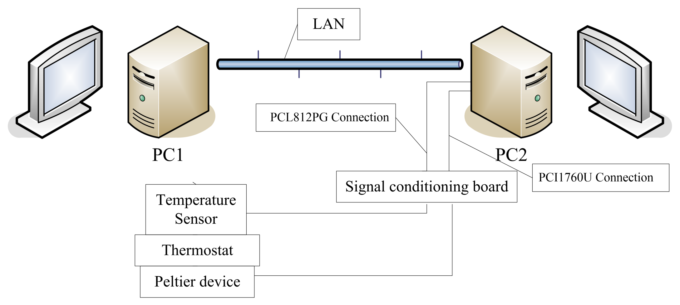
Figure 1. Experimental system.
Applsci 12 06084 g001
Figure 2. Thermostat system.
Applsci 12 06084 g002
Figure 3. The configuration of the Peltier device.
Applsci 12 06084 g003
Figure 4. The configuration of the thermostat.
Applsci 12 06084 g004
Figure 5. Network delays.
Applsci 12 06084 g005
Figure 6. Adaptive output following control based on identification model.
Applsci 12 06084 g006
Figure 7. Simulation result of the CGT-based method [20].
Applsci 12 06084 g007
Figure 8. Simulation result of the proposed method.
Applsci 12 06084 g008
Figure 9. Parameter estimation of the proposed method.
Applsci 12 06084 g009
Figure 10. Simulation results of the proposed method for time-varying NCSs.
Applsci 12 06084 g010
Figure 11. Parameter estimation of the proposed method for time-varying NCSs.
Applsci 12 06084 g011
Figure 12. Experimental parameter estimation of the proposed method.
Applsci 12 06084 g012
Figure 13. Parameter estimation when a 1 becomes 1.
Applsci 12 06084 g013
Figure 14. Experimental results of the proposed method.
Applsci 12 06084 g014
Figure 15. Experimental results with difference reference input.
Applsci 12 06084 g015
Table 1. Parameters of the thermostat.
d 1 The outer length of thermostat
d 2 The outer width of thermostat
d 3 The outer height of thermostat
d 4 The length of peltier
d 5 The width of peltier
d 6 The thickness of thermostat
Publisher’s Note: MDPI stays neutral with regard to jurisdictional claims in published maps and institutional affiliations.