Abstract
This paper reports a new medical device together with a control strategy that focuses on the following tasks: (1) a trajectory tracking problem associated with the supination–pronation motion of the wrist–forearm for purposes of rehabilitation and (2) the adjustment of the system’s stiffness associated with the applied torque guaranteeing the angular motion of the rehabilitator as well as the resistance that potential users must overcome. These two tasks are oriented to regain the range of motion (ROM) of the wrist–forearm and to improve the strength of the associated muscles. It is worth mentioning that this device has not been clinically validated. However, the performance of the closed-loop medical device is validated with preliminary experiments with a healthy subject based on movement patterns involving passive, assisted-resisted, and active phases of rehabilitation protocols.
1. Introduction
In 2019, according to the Mexican Instituto Nacional de Estadística y Geografía (INEGI), there were about 7.7 million people (over 5 years old) with disabilities difficulties in carrying out their activities of daily living (ADL); of this total, the percentage of people who are affected by the upper limb disability is 18.1% [1]. The main causes of disability are reported in [2]: diseases, injuries, and advanced age are the ones that stand out. Due to the inability to fully or partially move the upper limb, patient limitation to perform basic ADL causes a reduction in her/his quality of life.
In order to treat upper limb dysfunctions, several approaches can be considered by physical therapists. “Neurodevelopmental treatment (NDT) techniques, bilateral arm training, robot-assisted training, constraint-induced movement therapy, and neuromuscular electrical stimulation” [3] are examples of such approaches. The objective of NDT is to improve the natural function that controls motion in patients with neurological problems [4]. The simultaneous use of both upper extremities to reproduce the same exercises and characterizes the bilateral arm training approach while medical devices identified as robotic systems define the robot-assisted training approach, where this kind of systems can be used in passive, active, and strength increase rehabilitation stages [5]. Restraining the healthy upper limb, large energy training with the paretic extremity, and conductual use of the paretic limb outside the clinical environment are elements that characterize the constraint-induced movement therapy. When neuromuscular electrical stimulation is used, an electric current is applied in order to produce contractions in the affected muscles [5].
Other techniques to treat affected upper limbs can be identified as unilateral or bilateral approaches. In the unilateral context only the affected limb is involved, while, in the bilateral one, both limbs perform physical exercises [6]. Brain or spinal cord trauma, strokes, and multiple sclerosis are some of the problems that can be treated with therapeutic techniques. On the other hand, specialists could recommend well-known common exercises as stretching, resistance exercises or working with weights, depending on the patient’s medical condition.
Usually, rehabilitation protocols require the supervision of a therapist to help the patient in performing exercises and tasks. However, the shortage of therapists, the limited coverage of health systems, and the absence of trained services restrict the patient’s complete rehabilitation [7]. This scenario suggests that the introduction of robots or automatic devices might significantly contribute to improving the results of rehabilitation programs [8]. Different studies [9,10,11,12] have shown that rehabilitation robots are ideal tools to complement classical physical therapy due to standardization, repeatability, intensive training, and cost reduction, which can significantly improve motor skills.
Motor learning and motor control improve when patients practice functional tasks with stimulation, such as reaching objects or playing games, which can improve muscular strength, movement coordination, and prevent secondary complications such as muscle atrophy, osteoporosis, or spasticity [13,14]. Rehabilitation based on virtual reality have demonstrate advantages of using these technologies in motivating patients to perform exercises in a more dynamic and interactive manner [15]. Patient active participation is crucial for increasing robotic rehabilitation efficacy. For instance, impedance-admittance control techniques and patient-cooperative methods have been proposed to adapt robotic assistance according to the disability level and voluntary participation of human subjects [16]. Robot-assisted therapy proposed in [17] enables highly repetitive, intensive, and quantifiable physical training, with the purpose of restoring a loss of motor function in patients with neuromuscular conditions.
To the best of the authors’ knowledge, there is a deficit in rehabilitation robots that are compact enough, light, and powerful enough in carrying out rehabilitation exercises. Moreover, the recommendation for new developments concerning medical devices, provided by the sustainable development agenda of the United Nations, establishes that these systems must be light weight and accessible [18].
Systems with elastic joints have gained interest in the rehabilitation robotics community due to the compliant robot interaction with the patient and the therapist. Adjustable stiffness robots promise to be beneficial regarding robustness and task adaptability [19,20], and they are developed to be passively compliant, robust, and dexterous. Systems with similar characteristics are mentioned below.
Tensegrity systems are self-stressed systems defined as a set of compressed bars in a set of tensioned elements that can be either rigid or elastic cables [21]. Due to their lightness, compliance, flexibility, and architecture, tensegrity robots demonstrate structural properties that provide them with attributes similar to their biological counterparts, which make them ideal for rehabilitation [22]. In [23], a wearable and compliant robot is designed to harmonize with the human body’s upper limb where a network of tensioned lines (cables) connected with motors provides augmentative and compliance forces to perform natural arm movements.
Cable-driven systems have desirable features, including a large workspace, easy implementation, lightness, reconfiguration, and high-speed movement [24]. In [25], a cable-driven articulated system was designed to assist repetitive gait training by changing cable lengths. This adjustment generates a new configuration (geometrical form), producing a change in its stiffness. According to [26], control schemes that deal with both reconfiguration and adjustable stiffness in the cable-driven and tensegrity systems are difficult to obtain.
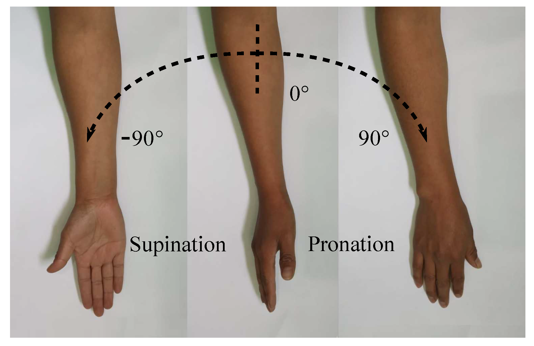
The purpose of the current study is to develop and control a supination–pronation device that is able to recreate therapy exercises with or without intervention of a physical therapist. The full wrist–forearm supination–pronation ROM is shown in Figure 1, which represents the motion of interest in this paper. It is highlighted that, depending on the medical condition of each patient, the angular displacements provided by the system can be generated with smaller values than those illustrated in Figure 1.
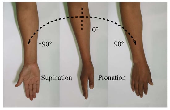
Figure 1.
Supination–pronation of the entire ROM.
Since most rehabilitation exercises result in repetitive movements, these can be performed by an appropriate rehabilitation device, but only a few rehabilitation devices are capable to perform the three phases of rehabilitation [27]. One of the main objectives in rehabilitation systems is to allow flexibility in movements, forces, and a customized training regime. Then, according to different rehabilitation phases, system reconfiguration can be achieved by using cables while springs or flexible elements allow adjusting the stiffness of the system.
Upper limb devices can be divided into prosthesis and orthosis: “A prosthesis is an artificial device that is used to replace or augment a missing or impaired part of the body. An orthosis is an orthopedic appliance or apparatus used to support, align, prevent, or correct deformities or to improve the function of movable parts of the body” [28]. Orthosis can further be divided in extension modules of the task-space arm and exoskeleton rehabilitation devices.
Some rehabilitation devices focusing on the wrist and forearm joints are briefly described in Table 1. The main disadvantage of these devices is the inability to modify torques in order to recreate different rehabilitation phases.

Table 1.
Characteristics of wrist–forearm rehabilitation devices.
The study reported in this paper focuses on the development and control of an original adjustable stiffness rehabilitation device that is lightweight and accessible. This rehabilitator meets the needs of wrist–forearm supination–pronation rehabilitation protocols that consider the tracking of a cyclic trajectory and the regulation of its stiffness, representing the torque that potential users need to overcome in order to regain strength in their muscles.
Remark 1.
No individuals with specific medical conditions (physical affectations) participated when performing the experimental tests reported in this paper. A healthy volunteer signed an informed consent document to participate in the experimental tests oriented to evaluate the performance of the device. The study is not oriented to clinical studies related to the evolution of patients’ medical conditions using the adjustable stiffness rehabilitator. This paper presents a new medical device focusing on its performance under a closed-loop control configuration in order to track specific trajectories and adjust the system’s stiffness.
Rehabilitation depends on the intensive and continuous practice of movements and exercises. Physical rehabilitation consists of three exercise phases: passive, active-assisted, and active [37,38]. In conventional therapy sessions, for passive exercises, also known as passive ROM exercises, a therapist helps in moving muscles and joints through their full ROM and the patient does not exert any effort. Active-assisted exercises are executed when the patient’s muscles are weak; i.e., the patient has difficulty in performing the exercises by himself/herself; then, a therapist assists movements. Active exercises are performed when the patient can move without assistance; in this phase, external resistance that helps in increasing power and endurance of the muscles is useful and desirable.
Supination–pronation rehab exercises help regain motion and build strength in one of the most crucial body parts: the forearm. Without the proper functioning of this part of the body, performing ADL would be difficult and is even impossible. When a patient is performing rehabilitation for the forearm, the following general guidelines are recommended in [38,39,40]:
- Phase 1. Immediate motion (Passive)
The objectives of this phase are to minimize the effects of immobilization and reestablish non-painful elbow forearm ROM. The recommended frequency of exercises is six times a day for 10 to 15 minutes each time while avoiding lifting or carrying any objects. Immediate motion decreases pain and inflammation, avoiding muscular atrophy.
- Phase 2. Intermediate (Active-assisted)
The starts six weeks after the injury, when the affected joint capsule is well healed and full ROM is recovered (as it was before the injury). In this phase, muscular strength and endurance are improved through ADL. In addition, repetitive active-assisted exercises are limited to work with weights from 0.5 to 1.0 kg.
- Phase 3. Advanced strengthening (Active)
At approximately week eight, the forearm muscles begin to gain strength through the use of free weights (1 to 2 kg) and elastic resistance (e.g., resistance bands) in order to exert a particular amount of tension on the muscles. Forearm-wrist movements such as closed chain exercises (exercises performed with the distal part of the limb under rehabilitation fixed to a stationary object) were implemented in this phase.
An original mechatronic medical device with a simple mechanical subsystem that reproduces the desired angular motions while providing desired values of stiffness, together with a theoretical-practical solution to, effectively, accomplish these tasks in a closed-loop configuration are the main contributions of this paper.
This paper is organized as follows. Section 2 identifies the methods that were used in order to develop and validates the adjustable stiffness rehabilitator reported in this paper. Section 3 presents the wrist–forearm rehabilitation system with adjustable stiffness. Section 4 provides information related with the electronic components used to control the rehabilitation device. Section 5 reports the control strategy to track the trajectory associated with the rehabilitation angular motion of the wrist–forearm and to adjust the stiffness of the device through the regulation of the system tension forces. Preliminary experimental results that validate the functionality of the reported device are presented in Section 6. Conclusions are found at the end of the paper.
2. Methodology
This section illustrates the methodology used to develop the adjustable stiffness rehabilitator and to validate its performance. The steps mentioned below constitute a well-known general method for developing medical devices
- Medical requirements identification: The characterization of the required motion is established by performing a literature review and by consulting physiotherapists. Range of motion, torques, and physical dimensions are some of the requirements that must be defined.
- Mechanical design conceptualization: In this iterative phase, several concepts of the rehabilitator are generated in order to be evaluated based on medical requirements. Different mechanical elements and materials are considered, as well as manufacturing processes. The best option is selected to be developed. Figure 2 and Figure 3 show a schematic representation of some elements of the rehabilitator.
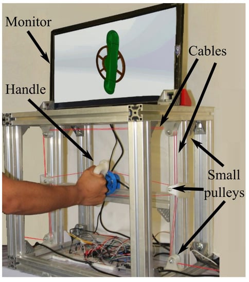 Figure 2. Experimental platform.
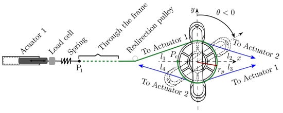 Figure 3. Handle and pulley-actuator interconnection.
 - Dynamic mathematical model synthesis: A dynamic mathematical representation of the selected option is synthesized, taking into account mechanical interactions defined by physical laws and behaviors of the respective materials. The dynamic mathematical model (DMM) can be obtained in the time domain. If the mathematical model is linear, a frequency domain representation can be obtained too. The DMM representing the adjustable stiffness rehabilitator is provided in Equation (2) in the time domain.
- Open loop numerical simulations: In order to analyze the behavior of the mathematical model under specific excitation signals, numerical simulations are performed. If needed, adjustments can be made to the mathematical model.
- Closed-loop control strategy synthesis: starting from a precise mathematical model of the rehabilitator, the synthesis of a closed-loop control strategy is generated by taking into account the angular position trajectory tracking (supination–pronation) and the cable’s tension regulation (resistance to be overcome). This is, in general, an iterative step. Section 5 shows the proposed closed-loop control strategy.
- Closed-loop numerical simulations: Several numerical simulations are performed in order to analyze the closed-loop behavior of the mathematical model (the rehabilitator) based on the established requirements. It is in this phase where the controllers are tuned. This step represents a first validation that allows one to initiate the manufacturing process.
- Experimental platform manufacturing: Based on the materials, on the mechanical elements, and on the manufacturing processes considered in the selected proposal, an experimental platform is built (see Figure 2). This platform will allow one to, experimentally, validate the mechanical design, the dynamic mathematical model, and the control strategy.
- Experimental platform instrumentation: Actuators, sensors, and other elements are incorporated to the experimental platform that will interact with an embedded system.
- Embedded system generation: Generally speaking, in this step a microcontroller is selected, programmed and connected to the manufactured and instrumented platform. At this point, the electronic interface (see Section 4) is ready for performing experiments.
- Experimental tests: Before using new medical technology in patients for clinical trials or treatment, it is necessary to validate, experimentally, its performance. The angular trajectory tracking and the stiffness (tension or torque) regulation are the two main aspects of interest to validate the performance of the rehabilitator reported in this paper (see Section 6).
3. Adjustable Stiffness Rehabilitation Device
Figure 2 is a photograph of the developed experimental platform of the adjustable stiffness medical device reported in this paper. The main element is the handle that, automatically, reproduces the required supination–pronation angular motion. In Figure 2, a right forearm-hand is driven by the handle of the system through the pulley (in blue) that receives four non-elastic cables (in red) that are connected to two linear electric actuators (not visible in the photo). The aluminum frame provides structural stability and serves as a support for the handle and for a set of redirection small pulleys (in white) that can be observed thanks to the change of direction of the cables from horizontal to vertical. This set of small pulleys serves to redirect the cables through the frame. An auxiliary monitor that is used during the active-assisted phase of the rehabilitation protocol displays the desired trajectory to be followed.
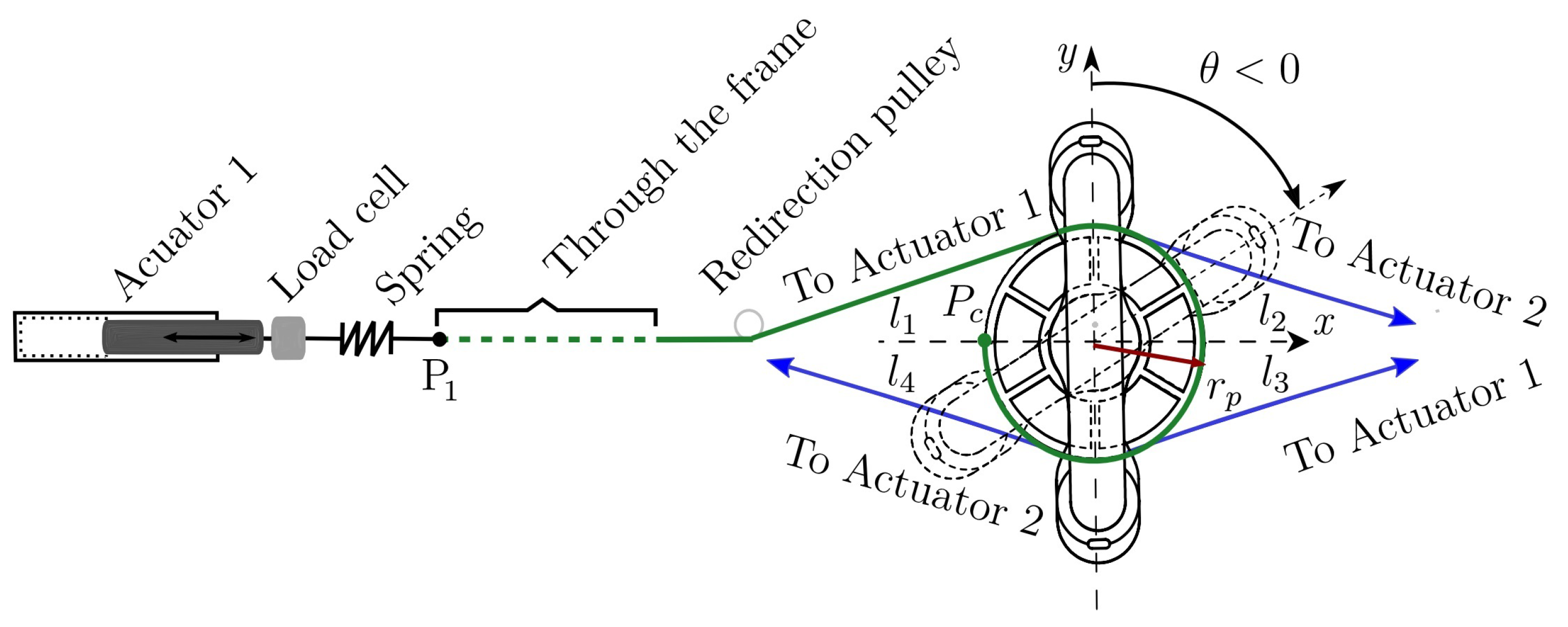
Figure 3 illustrates the way cables interact with the handle and how they are connected to the actuators. The combined actions of four forces , and acting, respectively, through four cables (in green), , , and (in blue) generate the angular motion defined by . As it is illustrated in Figure 3, cables and are driven by actuator 1 while cables and are driven by actuator 2.
In addition, Figure 3 illustrates the way each cable is attached to the handle pulley by highlighting that cable (in green) is connected to this pulley at point after winding on its surface. The four cables are tangent to the handle pulley with radius . Cable changes its direction several times thanks to the aforementioned set of small pulleys, proceeding through the aluminum frame (dotted green line) to finish at point where cable arrives too. A spring and a load cell are placed between point and the end of the rod of linear actuator 1. Cables and are connected in a similar manner to linear actuator 2. Each spring allows adjusting the stiffness of the medical device, through the control strategy described in Section 5.
The motion of the rehabilitation system is performed on the plane. Then, torque generating the desired angular motion is always parallel to the z-axis. In Figure 3, the handle is vertical at the initial (neutral) condition (solid lines). If the handle rotates clockwise, (dashed lines). Otherwise, .
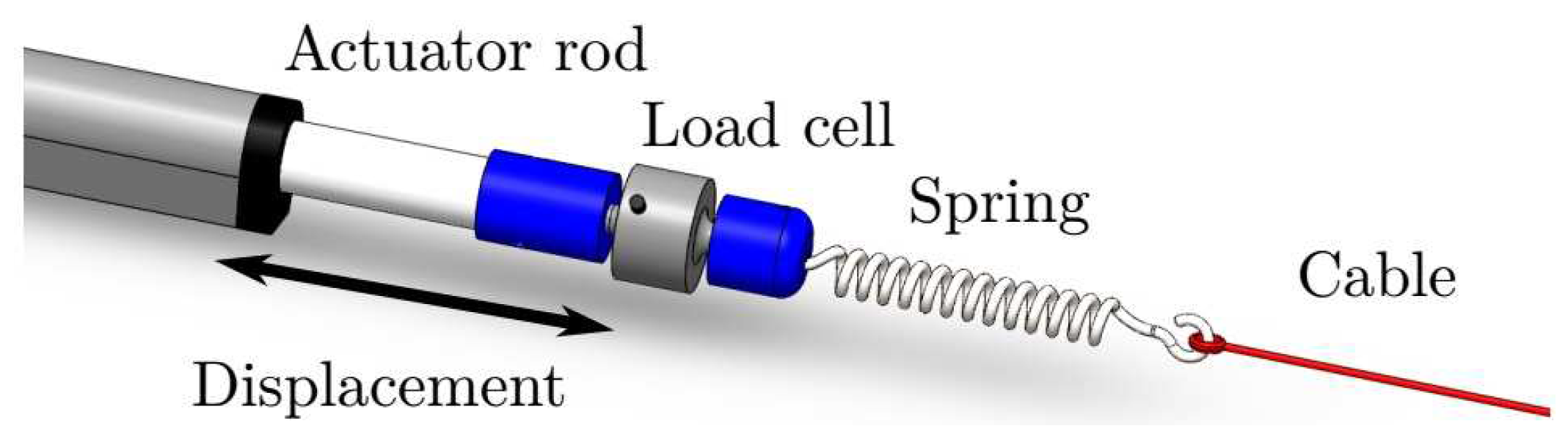
Figure 4 illustrates, in a more detailed manner, how cables are driven by actuators. A first connector (in blue) is placed between each actuator rod and a load cell. A second connector (in blue) is placed between that load cell and a spring that receives the respective pair of cables (in red). The double-headed arrow illustrates the displacement that each linear actuator can produce, resulting in a change in the tension of the respective pair of cables.

Figure 4.
Linear actuator, load cell, spring, and cable assembling.
It is highlighted that cables and are rigidly attached to a first spring in the same manner that cables and are attached to a second spring. The two springs have the same stiffness value (185.39 N/m).
According to existing wrist–forearm rehabilitation protocols for supination–pronation exercises (see [38,39,40]), the following procedures for the use of the adjustable stiffness device reported in this paper are suggested:
- •
- Grasp the patient’s wrist, supporting the hand with the handle, and stabilize the elbow and the forearm whether sitting or standing;
- •
- Supination and pronation should be performed with a 90° elbow/forearm flexion or with a 90° shoulder/arm flexion;
- •
- Supinate or pronate the forearm until a slight pain arises with previously established trajectories;
- •
- Apply resistance through stiffness control actions as the patient evolves in his/her rehabilitation.
To achieve full forearm rehabilitation, the adjustable stiffness device must be prepared for the implementation of the three aforementioned rehabilitation phases by means of an accurate trajectory tracking process and the possibility of adding or reducing loads during an exercise. Thus, three different command phases for wrist–forearm supination–pronation rehabilitation are identified as follows:
- Passive: A trajectory, previously established by a therapist as a function of the patient’s medical condition, is tracked at different angular speeds by the adjustable stiffness rehabilitator. In this therapy phase, the patient will not make any effort to perform the movement because the actuators will be in charge.
- Active-Assisted: The therapist defines a desired trajectory, and the patient is asked to move his/her wrist–forearm from the neutral position () toward a desired one. If the patient is not able to perform the desired movement, the rehabilitation device completes the task.
- Active: In this resisted phase, the desired trajectory and the tension values are previously established by the therapist. The rehabilitation device measures angular positions and tensions in the cables and provides the required forces to successfully complete the exercises. The control delivers a part of the required tension through springs deformations.
An important rehabilitation robot problem is related to the fact that the robot must fit around the respective human limb. This means that the robot must be ergonomic and provide comfort in treatment. Moreover, robotic joints and links must, physically, avoid human joints and links while performing motion in order to prevent pressure points (sores). Some exoskeletons have used ring bearings to enclose the forearm [33,34], allowing the rotation axis to lie within the forearm’s envelope.
The forearm supination–pronation movement results in a rotation axis inside the forearm. The one DOF of the adjustable stiffness rehabilitation system is associated with the rotation of the device about this axis. The device reported in this paper is adapted to the anthropomorphic measurements of the wrist–forearm, which have been analyzed in [41]. To allow proper training, the adjustable stiffness system must be able to move the patient’s wrist and forearm throughout the entire supination–pronation ROM (see Figure 1).
For wrist–forearm rehabilitation, the system configuration is as follows: The system has an initial pre-stress level such that tensions are equal () when the device is in its initial or neutral position (see in Figure 3). The linear actuators generate displacements in the aforementioned cables that produce torques, generating angular motion. The initial movement is the supination (pronation) motion when rehabilitating the right (left) hand. Once the desired ROM is achieved, the pronation (supination) motion starts, passing through the neutral position.
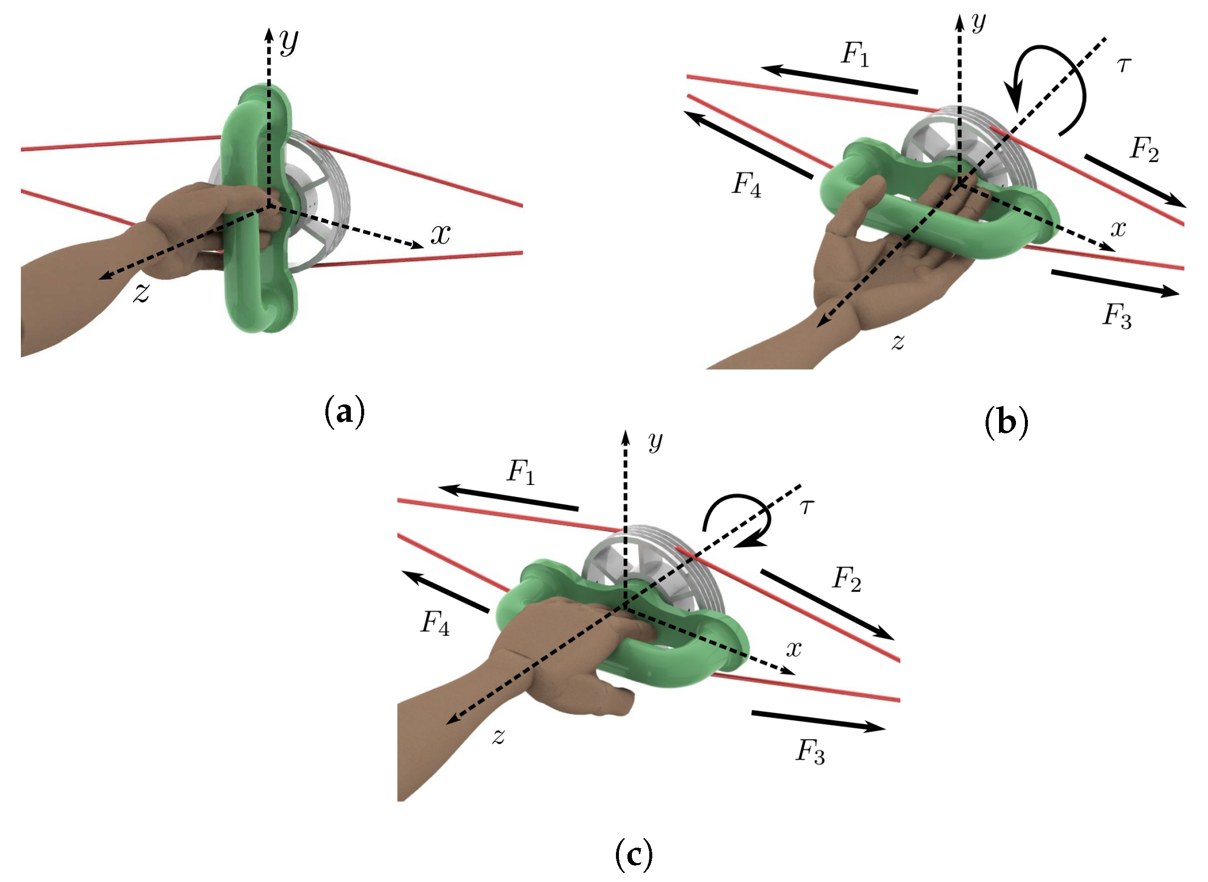
Figure 5 illustrates the movements that the reported system can generate. Starting at the neutral position (see Figure 5a) where , supination (Figure 5b) or pronation (Figure 5c) motion can follow. In neutral positions, the four tensions in the cables are equal. When performing supination, the torque produced by and is greater than the one produced by and , resulting in total torque illustrated in Figure 5b. This situation is reversed when performing pronation (see Figure 5c).

Figure 5.
Left wrist–forearm. (a) Neutral position. (b) Supination. (c) Pronation.
Since forces and are driven by actuator 1 while forces and are driven by actuator 2, it can be established that and (see Figure 3 and Figure 5). Taking into account that pulley radius is constant, the total torque generated by this device is provided in Equation (1).
It is highlighted that at all times with . Then, the total torque is always parallel to the z-axis.
The following details are aimed to provide a better understanding of the developed experimental platform:
- The springs are assumed to be linear elements working under tension at all times.
- Vibration and elongation in the cables are neglected.
- The linear actuators are mounted outside the system workspace. The standing or seated position of the patient requires that the actuators are not mounted under or above the forearm to prevent injuries.
- Safety must always be guaranteed for both the patient and the therapist by considering the following: to avoid sharp edges in the mechanical structure (aluminum and polylactic acid (PLA) parts). Several components of the experimental platform are manufactured by 3D-printing using PLA material. The design respects the anatomical ROM of human upper limbs. The chances of a severe accident are low because the maximum speed is limited by the properties of the linear actuators and by electronic-computational restrictions.
- The motion of the rehabilitation system is generated as follows (see Figure 4). Each linear actuator transmits a linear displacement to one end of the respective spring. Once the spring is deformed, the displacement is transmitted to the associated rigid cables. Each spring provides the possibility to modify the tensions in the cables according to a particular rehabilitation phase since smooth motions could be required depending on the patient’s medical condition. Moreover, tensions adjustments are required when performing assisted-active and active rehabilitation phases.
- The cables (copolymer monofilament) are used to connect the springs with the handle through a series of pulleys that modify the direction of each force in order to guarantee a constraint-free operation of the system.
- The system requires to meet and exceed the torque and the ROM requirements while recreating ADL movements (see Table 2).
Table 2. ROM and torque capabilities [33,42].
4. Electronic Interface
To operate the adjustable stiffness device with the implementation of the proposed control strategy, a Simulink model was created in order to use the rapid control prototyping method presented in [43,44], which made use of an embedded coder to translate control diagrams into a C program that can be imported as a function into the System Workbench for STM32 IDE that allows programming the microcontroller with C code that compiles and runs on an STM32F767ZI board.
Additionally, the activities performed by each of the electronic components and the control strategy are described next:
- The master board NUCLEO-F767ZI [45] is in charge to manage the control loop process at 1 kHz sample rate and the signal processing. It contains a low/high-level (general purpose input/output and trajectory/tension controllers) control strategy.
- Two linear actuators (TGA-Y-300-24-5-405) of 24 VDC and 900 N of maximum load are implemented. Additionally, it includes an internal micro switch to make the actuator’s stem stop automatically after it ends. Its displacement corresponds to 300 mm. Moreover, an external encoder (LPD3806-400BM-G5-24C) of 400 pulses per revolution (ppr) has been adapted to each actuator. Based on a quadrature method, the number of ppr has been incremented to 1600 in such a manner that the respective resolution equals 37,600 pulses per each displaced millimeter.
- To move the actuators, an L298N dual H-bridge DC motor driver module has been implemented. The speed and direction of each actuator is controlled by means of applying 12 bits pulse width modulation (PWM).
- Two load cells (JLBM-1-100) of 100 N, with mv/V of sensitivity, were implemented to convert the mechanical force of the cables-springs into analogue values to measure/calculate the system stiffness by means of two 12-bit ADC.
- In order to measure the angular position of the handle and to close the feedback trajectory loop, another incremental encoder with 1600 ppr was implemented.
Once the physical platform has been instrumented and its electronic interface has been implemented, the control strategy described in Section 5 can be experimentally validated. It is worth mentioning that the dynamic properties of both actuators are not considered in this paper.
5. Control Strategy
The dynamic model of the adjustable stiffness rehabilitation system with viscous friction is provided in Equation (2):
where , , , , and are physical parameters of the adjustable rehabilitation device for which its values are provided in Table 3. The control to be implemented is generated by the combined actions of two linear actuators, and , as .
Table 3.
Physical parameters.
Since wrist–forearm supination–pronation rehabilitation exercises produce cyclic movements, the control strategy reported in this paper focuses on a trajectory tracking problem. Then, a position-based force control strategy is synthesized with the following two main components:
- A proportional-integral-derivative (PID) controller in charge of ensuring trajectory tracking. The trajectories of interest are of the sinusoidal type , where represents the desired behavior of the handle angular position in degrees, A is the amplitude of the angular displacement in degrees, is the angular frequency in radians per second, and t is the time in seconds.Remark 2.Parameters A and ω can be adjusted according to a therapist recommendation based on the patient’s medical condition.
- A proportional-derivative (PD) controller focused on a regulation task. While the handle of the rehabilitation device changes its angular position, it is necessary to guarantee a desirable value of the tension force in the cables to ensure that the two springs always work with a minimum of elongation. It is highlighted that a desired tension value depends on the rehabilitation phase and on the patient’s medical condition.
Figure 6 depicts the general idea of the proposed control strategy, this technique combines tension and position control to satisfy the tasks related to the different rehabilitation phases.
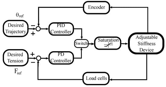
Figure 6.
Control diagram.
To execute the trajectory tracking task, the PID controller is used together with an encoder to capture the handle’s angular position. A second loop uses the PD controller together with two loads cells to obtain information about the tension in the cables. When tension regulation is required, the PD controller acts instead of the PID controller, during a pre-defined period of time. This alternate control action is performed by the switch observed in Figure 6. The saturation block refers to the system constraints such as actuator maximum speed or the admissible tension values of the cables.
Table 4 provides the values of the gains for the PID and PD controllers used in the control strategy for the adjustable stiffness rehabilitation system.
Table 4.
PID and PD gain values.
6. Experimental Results
Even when a set of numerical simulations was carried out, experimental results are priority to be reported in this paper. These results focus on the following three main aspects that define the behavior of the rehabilitation system:
- The handle angular motion with respect to a desired trajectory ;
- The tensions in the cables looking to keep a desired value;
- The total torque applied to the handle pulley that should be adjusted based on a desired value.
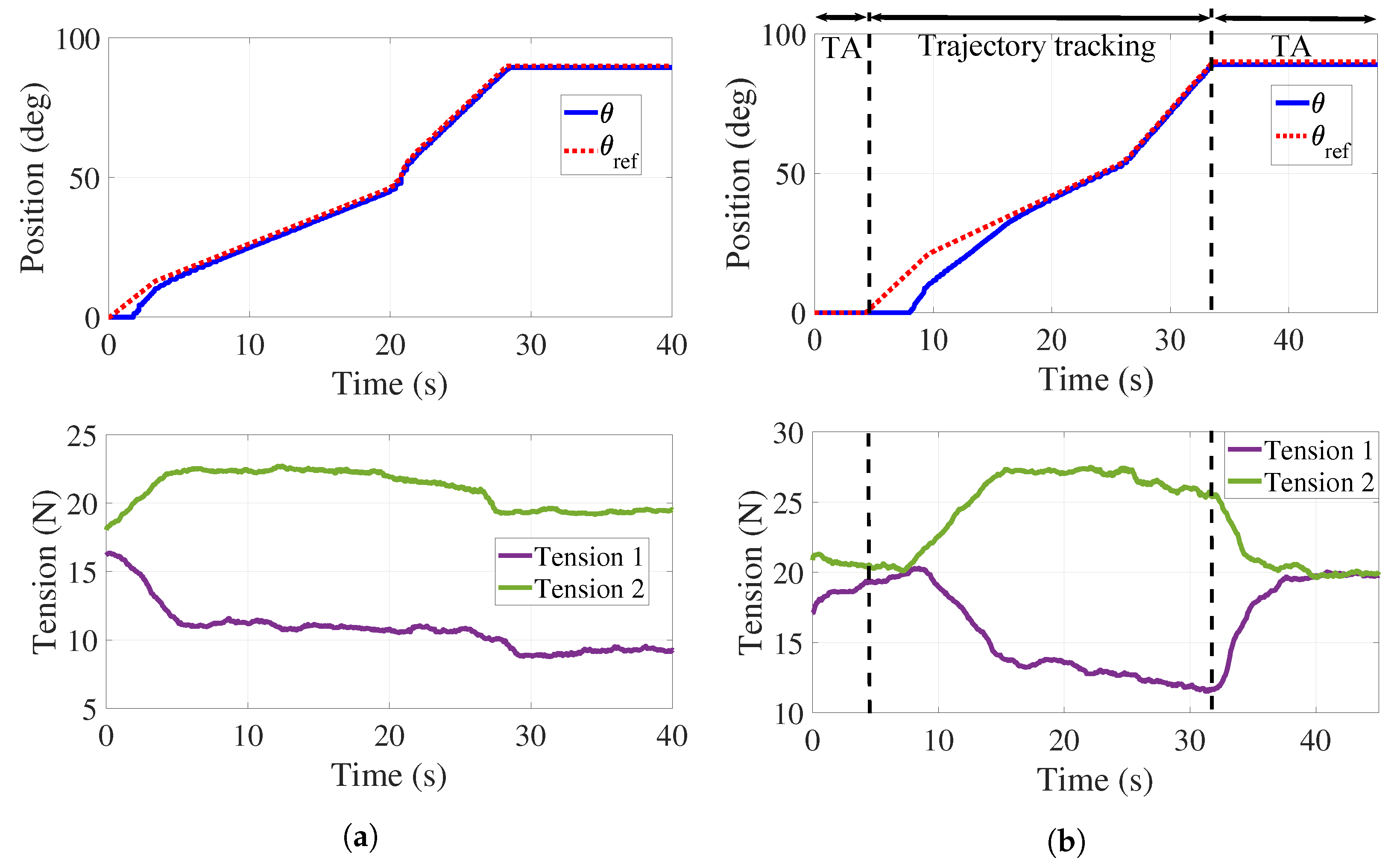
A first experiment was performed without the load associated with the hand–forearm of a person. Figure 7a shows the response of the handle when following a discrete time interpolated sequence , where the position input values are [0° 10° 45° 90°] and the time values are (in seconds) [0 4 21 28] under the PID controller. It can be observed that the handle follows the desired trajectory in an acceptable manner since the mean tracking error is . A dead zone can be observed for s due to the time required for the applied forces to overcome static friction. The bottom of Figure 7a reports the tensions behaviors when following . A decrease in the value of tensile forces in the cables is present since both springs experience different elongations and, consequently, tension variations when the handle follows the desired reference. An adjustment in the tension of the cables is then required.
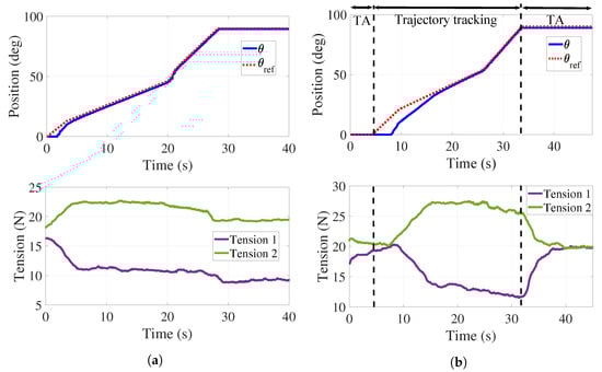
Figure 7.
Trajectory tracking and tension control. (a) Position control without tension adjustment. (b) Position control with tension adjustment.
Figure 7b reports the behavior of and those of the tensions when using both the PID and the PD controllers. Two tension adjustments (TA) are performed for N: the first one in s, and the second one in s. The mean tracking error for this test is . As it can be observed in the bottom of Figure 7b, both tensions are regulated at 20 N. It is highlighted that tension is that in cables and while is that in cables and . A more important dead zone is present at the top of Figure 7b that can be explained as the combined effect of static friction and the TA interval.
To illustrate the behavior of the system in each phase of a rehabilitation protocol (passive, active-assisted, and active), experimental trials were performed with a healthy person. Section 6.1, Section 6.2 and Section 6.3 present the outcomes of the proposed experiments.
6.1. Passive
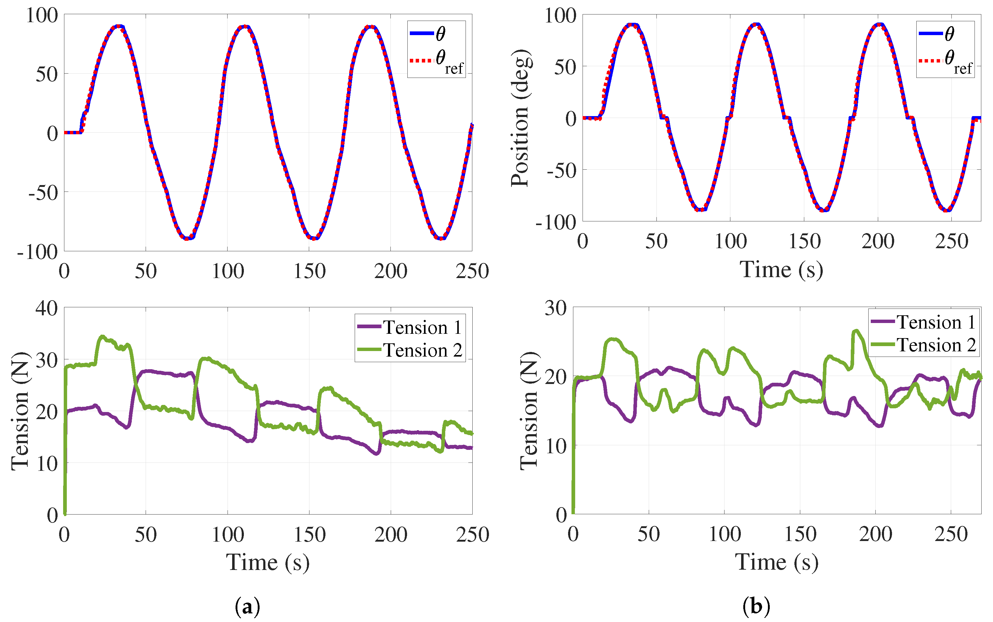
For this experiment, a reference provided by is proposed to emulate the complete supination–pronation ROM with a range of angular speeds that proceeds from 4 to 9/s. The desired tension in the cables is set to N. It is noted that the participant does not exert any effort to when the system is performing the desired movement. Figure 8 shows the obtained results.
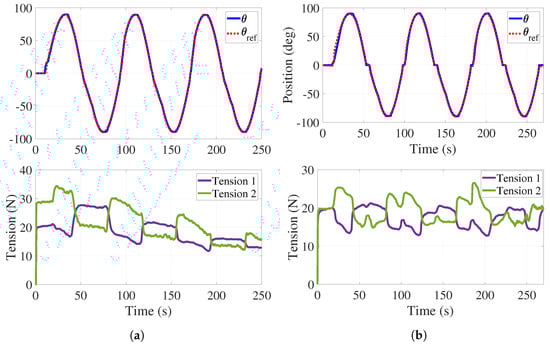
Figure 8.
Passive phase. (a) Trajectory tracking without tension control with load. (b) Trajectory tracking with tension control with load.
The top of Figure 8a illustrates the angular behavior of the handle without tension adjustment. As in Figure 7, a dead zone is observed at the beginning of the experiment and the mean tracking error is . The bottom of Figure 8a shows both tensions decreasing while the experiment is taking place.
Tension adjustments are implemented (see Figure 8b) initially in s, and then every time the handle crosses the neutral position () for a period of 3 s. The top of Figure 8b shows the handle angular behavior with some variations in the form of plateaus. These effects correspond to the tension adjustments reported at the bottom of Figure 8b where it is observed that tension in the cables is preserved. For this test, the mean tracking error is . As it can be observed in Figure 7 and Figure 8, the regulation of the tension forces is satisfactorily achieved with the control strategy previously described. It is worth mentioning that the error values obtained in these experiments are completely acceptable from the point of view of therapists.
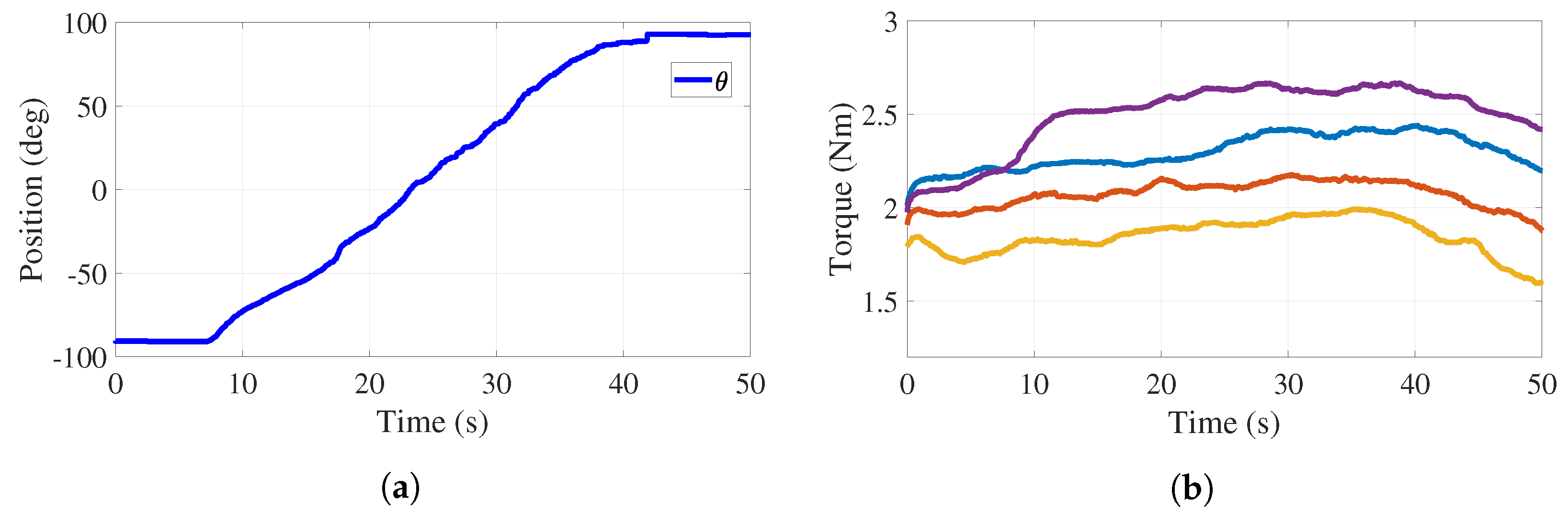
For active-assisted and active rehabilitation phases, it is necessary for the applied torque to be adjustable through tension variations in the cables. Figure 9a reports the behavior of the handle angular position when the participant is performing a pronation motion with the right hand and forearm (from to ).
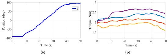
Figure 9.
Trajectory tracking and torque adjustment (cables and ) with load. (a) Handle position. (b) Torque behavior.
In this experiment, actuator 1 tracks while actuator 2 performs a tension adjustment. This experiment was carried out with an auxiliary monitor where the desired handle motion was deployed in order for the participant to emulate this trajectory. The control strategy keeps the tension constant. Figure 9b reports four behaviors of the torque applied to the handle pulley by cables and , which shows that the tension control can modify the torque depending on the patient’s strength. The values of these torques are 1.8 Nm (yellow), 2.1 Nm (orange), 2.3 Nm (blue), and 2.6 Nm (purple). The behaviors reported in Figure 9 allow one to conclude that the stiffness of the medical device, associated with the applied torque or to the resistance that a user must overcome, can be adjusted to desired values.
6.2. Active-Assisted
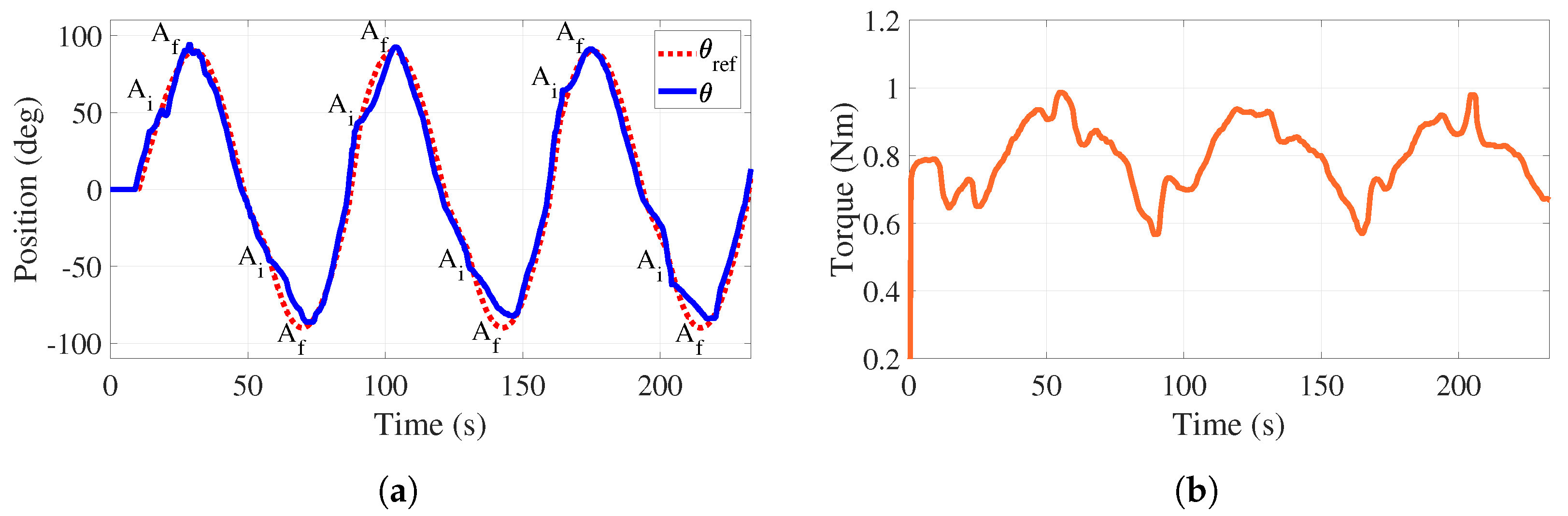
To carry out this experiment, the participant tries to recreate a desired trajectory (see red dotted line in Figure 10a) that is shown in an auxiliary monitor. The goal for the participant is to follow the path as far as possible while keeping a, relatively, small torque applied to the handle when performing the supination–pronation motion. If the participant is unable to complete the task, the system will provide help to complete it.
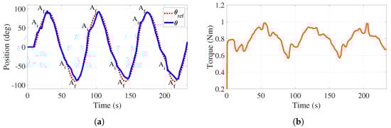
Figure 10.
Active-assisted phase. Trajectory tracking and total torque behaviors with load. (a) Handle position. (b) Torque behavior.
Figure 10a reports the motion generated by the participant (blue line) as well as the reference trajectory (red line). The time intervals where the system helps the participant in completing the task are identified by A when the assistance initiates (50° and °) and by A when it finishes (90° and °). It is highlighted that the assistance finishes when the handle is in horizontal configurations for three cycles of motion.
Figure 10b illustrates how the applied torque evolves. As it can be observed, the mean value of this torque equals 0.8 Nm, which matches well with the requirement related to the application of a small torque. In this case, there is no control action on the tensions, allowing these forces and, consequently, the applied torque to freely evolve. The torque variations (increase and decrease) observed in Figure 10b are associated with the assistance that is provided by the control strategy to complete the task.
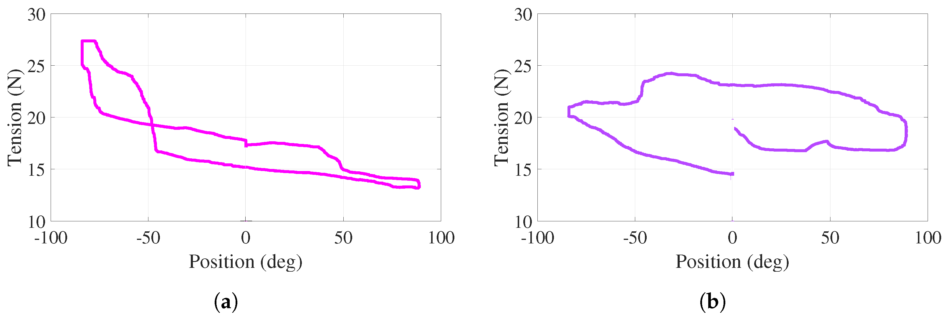
For this active-assisted experiment, the behavior of tensions in cables – (–) with respect to the angular position of the handle, for one cycle of the trajectory shown in Figure 10a, is illustrated in Figure 11a,b. Note that this cycle starts at , proceeds to (bottom of the curves), returns to (top of the curves), proceeds to , and finishes at ( s). In the vicinity of and , more significant variations, corresponding to the aforementioned assistance, are observed. For the entire experiment, both behaviors show positive tension values with variations less than 13 N. Discontinuities at 0 in Figure 11 are due to the fact that torque evolves freely (without control action), as observed in Figure 10b.
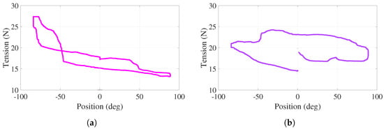
Figure 11.
Active-assisted phase. Tensions as a function of the angular position (a) . (b) .
6.3. Active
During this experiment, the participant exerts the effort necessary to perform supination–pronation movements, overcoming a predefined tension in the cables and, therefore, a predefined torque. It is highlighted that the value of this predefined torque can be adjusted depending on the patient’s medical condition.
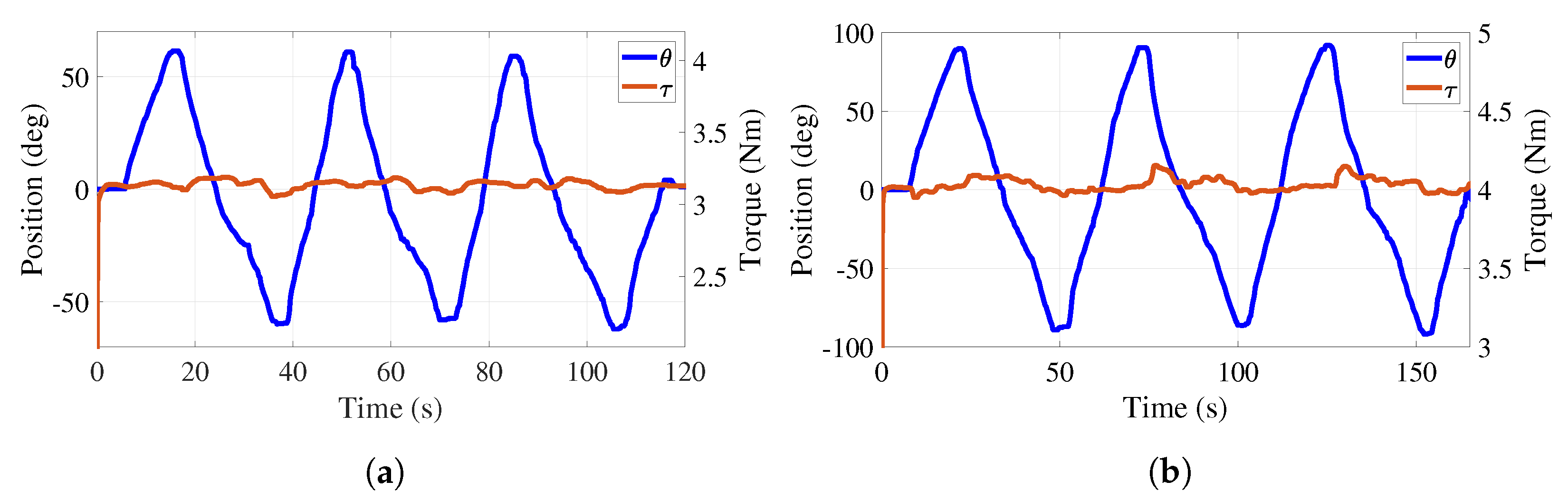
Figure 12a reports a 60° amplitude sinusoidal trajectory that the participant generates overcoming a predefined torque of 3.1 Nm. The regulation of this torque provides a mean error of 0.064 Nm. Figure 12b reports a 90° amplitude sinusoidal trajectory that the participant generates overcoming a predefined torque of 4 Nm. The regulation of this torque provides a mean error of 0.071 Nm. This illustrates that the torque adjustment is independent of the desired trajectory. The participant could interrupt the angular motion of the handle, rest a moment, and continue the exercise to complete the task. Evidently, the predefined value of the torque can be adjusted according to the therapist’s demand.
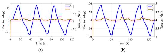
Figure 12.
Active phase. Trajectory tracking and total torque behaviors with load. (a) Torque at 3.1 Nm. (b) Torque at 4 Nm.
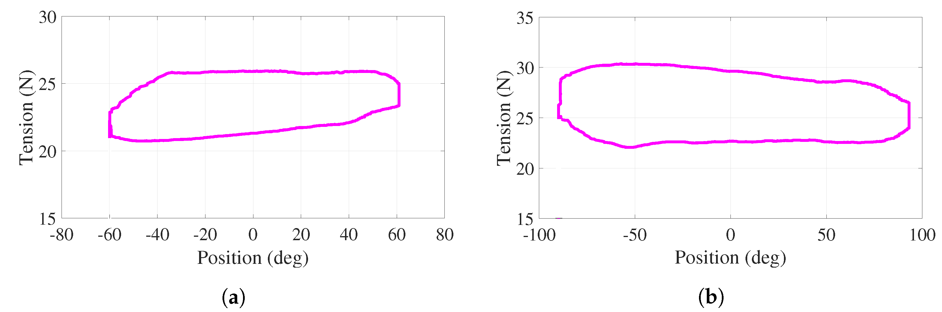
For this active experiment, the behavior of the tension in cables – with respect to the angular position of the handle, for one cycle of the trajectory shown in Figure 12a,b, is illustrated in Figure 13a,b. Note that this cycle starts at , proceeds to () following the bottom of the curve, returns to (top of the curve), proceeds to (), and finishes at when s ( s). These are the smooth behaviors under positive tension values with variations less than 8 N. Although the tension in cables – varies, the net torque is regulated to 3.1 N (4 N) by the action of the PD controller.
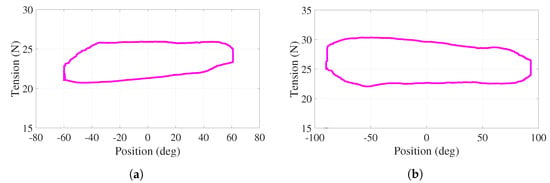
Figure 13.
Active phase. Tensions as a function of the angular position for cables (a) , (b)
.
7. Conclusions
A new rehabilitation medical device focused on wrist–forearm supination–pronation exercises, as part of rehabilitation protocols, has been reported in this paper. The reported device is based on an adjustable stiffness approach in order to adapt different torque values to the medical conditions of potential patients. Based on experimental tests, the effectiveness of the rehabilitation device has been demonstrated.
Three main aspects have been validated: the effective trajectory tracking performed by the system where small tracking error values have been obtained, its capacity to regulate tensions in the cables as a result of the proportional-derivative action of the proposed closed-loop control strategy, and its capacity to adjust and control, with small error values, the resistance torque that represents the adjustment in the system stiffness. The execution of the wrist–forearm supination–pronation task, through several cycles, has been experimentally validated by modifying the tension in the cables and, therefore, the effective torque in the handle of the device. This desired modification is guaranteed by contracting and elongating two springs when the control signals generated by two linear actuators act on the respective cables of the mechanical system.
The performance of the adjustable stiffness rehabilitator reported in this paper to be used in the passive, in the active-assisted, and in the active phases of rehabilitation protocols has been demonstrated by conducting experimental tests that provide satisfactory results.
The proposed control strategy has been experimentally assessed in terms of angular trajectory tracking and adjustable stiffness (regulation) for the three phases of rehabilitation.
Author Contributions
A.C.-R. developed the practical aspects of this research, J.C.Á.-V. provided original schematic, exhaustive work on reviewing and editing, and supervised this research, B.S., A.H.V.-G., and J.C.Á.-V. reviewed, edited, and corrected this document, and J.M.J.-V. supervised the embedded prototyping system. All authors participated in reviewing and writing this manuscript. All authors have read and agreed to the published version of the manuscript.
Funding
CONACYT Grant 373609.
Institutional Review Board Statement
Not applicable.
Informed Consent Statement
Not applicable.
Data Availability Statement
The data used to support the findings of this study are available from the corresponding author upon request.
Conflicts of Interest
The authors declare no conflict of interest.
References
- INEGI. Estadísticas a Propósito del día Internacional de las Personas con Discapacidad. 2019. Available online: https://www.inegi.org.mx/contenidos/saladeprensa/aproposito/2019/Discapacidad2019_Nal.pdf (accessed on 29 December 2021).
- Nusselder, W.J.; Looman, C.C.; Van Oyen, H.; Yokota, R.T.D.C. Attributing causes to disability. In International Handbook of Health Expectancies; Springer: Berlin/Heidelberg, Germany, 2020; Volume 9, pp. 87–105. [Google Scholar] [CrossRef]
- ATrain Education. Regaining Use of the Upper Extremity. 2022. Available online: https://www.atrainceu.com/content/13-regaining-use-upper-extremity (accessed on 18 May 2022).
- Kennedy Krieger Institute. Neurodevelopmental Treatment in Physical Therapy. 2022. Available online: https://www.kennedykrieger.org/patient-care/centers-and-programs/physical-therapy-clinic/neurodevelopmental-treatment (accessed on 17 May 2022).
- Canadian Partnership for Stroke Recovery. Upper Extremity Motor Rehabilitation Interventions. 2018. Available online: http://www.ebrsr.com/sites/default/files/ch%2010_v19.pdf (accessed on 17 May 2022).
- Narayan, J.; Kalita, B.; Dwivedy, S.K. Development of robot-based upper limb devices for rehabilitation purposes: A systematic review. Augment. Hum. Res. 2021, 6, 4. [Google Scholar] [CrossRef]
- World Health Organization. World Report on Disability; World Health Organization: Geneva, Switzerland, 2011. [Google Scholar]
- Masiero, S.; Poli, P.; Rosati, G.; Zanotto, D.; Iosa, M.; Paolucci, S.; Morone, G. The value of robotic systems in stroke rehabilitation. Expert Rev. Med. Devices 2014, 11, 187–198. [Google Scholar] [CrossRef] [PubMed]
- Nef, T.; Klamroth-Marganska, V.; Keller, U.; Riener, R. Three-dimensional multi-degree-of-freedom arm therapy robot (ARMin). In Neurorehabilitation Technology; Springer: Berlin/Heidelberg, Germany, 2016; pp. 351–374. [Google Scholar] [CrossRef]
- Sale, P.; Lombardi, V.; Franceschini, M. Hand robotics rehabilitation: Feasibility and preliminary results of a robotic treatment in patients with hemiparesis. Stroke Res. Treat. 2012, 2012, 820931. [Google Scholar] [CrossRef] [PubMed] [Green Version]
- Lo, A.C. Clinical designs of recent robot rehabilitation trials. Am. J. Phys. Med. Rehabil. 2012, 91, S204–S216. [Google Scholar] [CrossRef] [PubMed]
- Sale, P.; Franceschini, M.; Mazzoleni, S.; Palma, E.; Agosti, M.; Posteraro, F. Effects of upper limb robot-assisted therapy on motor recovery in subacute stroke patients. J. Neuroeng. Rehabil. 2014, 11, 104. [Google Scholar] [CrossRef] [PubMed] [Green Version]
- Hatem, S.M.; Saussez, G.; della Faille, M.; Prist, V.; Zhang, X.; Dispa, D.; Bleyenheuft, Y. Rehabilitation of motor function after stroke: A multiple systematic review focused on techniques to stimulate upper extremity recovery. Front. Hum. Neurosci. 2016, 10, 442. [Google Scholar] [CrossRef] [PubMed] [Green Version]
- Bertani, R.; Melegari, C.; Maria, C.; Bramanti, A.; Bramanti, P.; Calabrò, R.S. Effects of robot-assisted upper limb rehabilitation in stroke patients: A systematic review with meta-analysis. Neurol. Sci. 2017, 38, 1561–1569. [Google Scholar] [CrossRef] [PubMed]
- Padilla-Castañeda, M.A.; Sotgiu, E.; Barsotti, M.; Frisoli, A.; Orsini, P.; Martiradonna, A.; Laddaga, C.; Bergamasco, M. An orthopaedic robotic-assisted rehabilitation method of the forearm in virtual reality physiotherapy. J. Healthc. Eng. 2018, 2018, 7438609. [Google Scholar] [CrossRef] [PubMed]
- Jamwal, P.K.; Hussain, S.; Ghayesh, M.H.; Rogozina, S.V. Impedance control of an intrinsically compliant parallel ankle rehabilitation robot. IEEE Trans. Ind. Electron. 2016, 63, 3638–3647. [Google Scholar] [CrossRef]
- Duret, C.; Grosmaire, A.G.; Krebs, H.I. Robot-assisted therapy in upper extremity hemiparesis: Overview of an evidence-based approach. Front. Neurol. 2019, 10, 412. [Google Scholar] [CrossRef] [PubMed] [Green Version]
- UN. Transforming Our World: The 2030 Agenda for Sustainable Development. 2015. Available online: https://www.un.org/ga/search/viewdoc.asp?symbol=A/RES/70/1&Lang=E (accessed on 5 December 2021).
- Verl, A.; Albu-Schäffer, A.; Brock, O.; Raatz, A. Soft Robotics; Springer: Berlin/Heidelberg, Germany, 2015. [Google Scholar] [CrossRef]
- Wolf, S.; Grioli, G.; Eiberger, O.; Friedl, W.; Grebenstein, M.; Höppner, H.; Burdet, E.; Caldwell, D.G.; Carloni, R.; Catalano, M.G.; et al. Variable stiffness actuators: Review on design and components. IEEE/ASME Trans. Mechatronics 2015, 21, 2418–2430. [Google Scholar] [CrossRef]
- Motro, R. Tensegrity: Structural Systems for the Future; Elsevier: Amsterdam, The Netherlands, 2003. [Google Scholar] [CrossRef]
- Jung, E.; Ly, V.; Cessna, N.; Ngo, M.L.; Castro, D.; SunSpiral, V.; Teodorescu, M. Bio-inspired tensegrity flexural joints. In Proceedings of the 2018 IEEE International Conference on Robotics and Automation (ICRA), Brisbane, Australia, 21–25 May 2018; IEEE: Piscataway, NJ, USA, 2018; pp. 5561–5566. [Google Scholar] [CrossRef]
- Lessard, S.; Pansodtee, P.; Robbins, A.; Trombadore, J.M.; Kurniawan, S.; Teodorescu, M. A soft exosuit for flexible upper-extremity rehabilitation. IEEE Trans. Neural Syst. Rehabil. Eng. 2018, 26, 1604–1617. [Google Scholar] [CrossRef] [PubMed]
- Gosselin, C.; Cardou, P.; Bruckmann, T.; Pott, A. Cable-Driven Parallel Robots: Proceedings of the Third International Conference on Cable-Driven Parallel Robots; Springer: Berlin/Heidelberg, Germany, 2017; Volume 53. [Google Scholar] [CrossRef]
- Alamdari, A.; Krovi, V. Design and analysis of a cable-driven articulated rehabilitation system for gait training. J. Mech. Robot. 2016, 8, 051018. [Google Scholar] [CrossRef] [Green Version]
- Boehler, Q.; Abdelaziz, S.; Vedrines, M.; Poignet, P.; Renaud, P. From modeling to control of a variable stiffness device based on a cable-driven tensegrity mechanism. Mech. Mach. Theory 2017, 107, 1–12. [Google Scholar] [CrossRef] [Green Version]
- Manna, S.K.; Dubey, V.N. A Portable Elbow Exoskeleton for Three Stages of Rehabilitation. J. Mech. Robot. 2019, 11, 065002. [Google Scholar] [CrossRef] [Green Version]
- Medical Dictionary. Available online: http://medical-dictionary.thefreedictionary.com/ (accessed on 29 May 2019).
- Krebs, H.I.; Hogan, N.; Aisen, M.L.; Volpe, B.T. Robot-aided neurorehabilitation. IEEE Trans. Rehabil. Eng. 1998, 6, 75–87. [Google Scholar] [CrossRef] [Green Version]
- Charles, S.K.; Krebs, H.I.; Volpe, B.T.; Lynch, D.; Hogan, N. Wrist rehabilitation following stroke: Initial clinical results. In Proceedings of the 9th International Conference on Rehabilitation Robotics, 2005. ICORR 2005, Chicago, IL, USA, 28 June–1 July 2005; IEEE: Piscataway, NJ, USA, 2005; pp. 13–16. [Google Scholar] [CrossRef]
- Pehlivan, A.U.; Celik, O.; O’Malley, M.K. Mechanical design of a distal arm exoskeleton for stroke and spinal cord injury rehabilitation. In Proceedings of the 2011 IEEE International Conference on Rehabilitation Robotics, Zurich, Switzerland, 29 June–1 July 2011; IEEE: Piscataway, NJ, USA, 2011; pp. 1–5. [Google Scholar] [CrossRef]
- Allington, J.; Spencer, S.J.; Klein, J.; Buell, M.; Reinkensmeyer, D.J.; Bobrow, J. Supinator Extender (SUE): A pneumatically actuated robot for forearm/wrist rehabilitation after stroke. In Proceedings of the 2011 Annual International Conference of the IEEE Engineering in Medicine and Biology Society, Boston, MA, USA, 30 August–3 September 2011; IEEE: Piscataway, NJ, USA, 2011; pp. 1579–1582. [Google Scholar] [CrossRef]
- Martinez, J.A.; Ng, P.; Lu, S.; Campagna, M.S.; Celik, O. Design of wrist gimbal: A forearm and wrist exoskeleton for stroke rehabilitation. In Proceedings of the 2013 IEEE 13th International Conference on Rehabilitation Robotics (ICORR), Seattle, WA, USA, 24–26 June 2013; IEEE: Piscataway, NJ, USA, 2013; pp. 1–6. [Google Scholar] [CrossRef]
- Pehlivan, A.U.; Sergi, F.; Erwin, A.; Yozbatiran, N.; Francisco, G.E.; O’Malley, M.K. Design and validation of the RiceWrist-S exoskeleton for robotic rehabilitation after incomplete spinal cord injury. Robotica 2014, 32, 1415–1431. [Google Scholar] [CrossRef] [Green Version]
- Song, Z.; Guo, S.; Pang, M.; Zhang, S.; Xiao, N.; Gao, B.; Shi, L. Implementation of resistance training using an upper-limb exoskeleton rehabilitation device for elbow joint. J. Med. Biol. Eng. 2014, 34, 188–196. [Google Scholar] [CrossRef]
- Pezent, E.; Rose, C.G.; Deshpande, A.D.; O’Malley, M.K. Design and characterization of the openwrist: A robotic wrist exoskeleton for coordinated hand-wrist rehabilitation. In Proceedings of the 2017 International Conference on Rehabilitation Robotics (ICORR), London, UK, 17–20 July 2017; IEEE: Piscataway, NJ, USA, 2017; pp. 720–725. [Google Scholar] [CrossRef] [Green Version]
- Andrews, J.R.; Harrelson, G.L.; Wilk, K.E. Physical Rehabilitation of the Injured Athlete: Expert Consult-Online and Print; Elsevier Health Sciences: Amsterdam, The Netherlands, 2012. [Google Scholar] [CrossRef] [Green Version]
- Kisner, C.; Colby, L.A.; Borstad, J. Therapeutic Exercise: Foundations and Techniques; Fa Davis: Philadelphia, PA, USA, 2017. [Google Scholar]
- Wilk, K.E.; Ellenbecker, T.S.; Macrina, L.C. Rehabilitation of the overhead athlete’s elbow. In Elbow Ulnar Collateral Ligament Injury; Springer: Berlin/Heidelberg, Germany, 2021; pp. 327–356. [Google Scholar] [CrossRef]
- Giangarra, C.E.; Manske, R.C. Clinical Orthopaedic Rehabilitation: A Team Approach E-book; Elsevier Health Sciences: Amsterdam, The Netherlands, 2017. [Google Scholar]
- Avila-Chaurand, R.; Prado-León, L.; González-Muñoz, E. Dimensiones Antropométricas de la Población Latinoamericana: México, Cuba, Colombia, Chile / R. Avila Chaurand, L.R. Prado León, E.L. González Muñoz.; Universidad de Guadalajara: Guadalajara, Mexico, 2007. [Google Scholar]
- Tsagarakis, N.; Caldwell, D.; Medrano-Cerda, G. A 7 DOF pneumatic muscle actuator (pMA) powered exoskeleton. In Proceedings of the 8th IEEE International Workshop on Robot and Human Interaction. RO-MAN’99 (Cat. No. 99TH8483), Pisa, Italy, 27–29 September 1999; IEEE: Piscataway, NJ, USA, 1999; pp. 327–333. [Google Scholar] [CrossRef]
- Jacinto-Villegas, J.M.; Portillo-Rodríguez, O.; Martinez-Mendez, R.; Daza-Merino, C.; Vilchis-González, A.H.; Avila-Vilchis, J.C. Sistema para control de posición basado en Rapid Control Prototyping (RCP) usando Simulink y SWB32. Komput. Sapiens 2019, 3, 11–15. [Google Scholar]
- Martínez, C.C.; Ávila-Vilchis, J.C.; Jacinto-Villegas, J.M.; Saldivar, B.; Vilchis-González, A.H. Sliding Mode Control for the Regulation Problem of an Aerodynamic Angular System: Experimental Platform and Validation. Int. J. Control. Autom. Syst. 2021, 19, 2395–2405. [Google Scholar] [CrossRef]
- STMicroelectronics. NUCLEO-F767ZI. 2020. Available online: https://www.st.com/en/evaluation-tools/nucleo-f767zi.html (accessed on 18 January 2021).


Publisher’s Note: MDPI stays neutral with regard to jurisdictional claims in published maps and institutional affiliations. |
© 2022 by the authors. Licensee MDPI, Basel, Switzerland. This article is an open access article distributed under the terms and conditions of the Creative Commons Attribution (CC BY) license (https://creativecommons.org/licenses/by/4.0/).