Article

Intramode Brillouin Scattering Properties of Single-Crystal Lithium Niobate Optical Fiber

1
School of Instrument and Electronics, North University of China, Taiyuan 030051, China
2
College of Mechatronics Engineering, North University of China, Taiyuan 030051, China
*
Author to whom correspondence should be addressed.
Appl. Sci. 2022, 12(13), 6476; https://doi.org/10.3390/app12136476
Submission received: 27 May 2022 / Revised: 17 June 2022 / Accepted: 20 June 2022 / Published: 26 June 2022
(This article belongs to the Special Issue Advances and Application of Lithium Niobate)

Abstract

:
Ordinary step-type fiber usually has only one obvious Brillouin scattering gain peak with a low gain coefficient, resulting in a poor sensing performance. As a promising material for nonlinear photonics, lithium niobate can significantly improve the Brillouin gain due to its higher refractive index when replaced with the core material. Furthermore, the higher-order acoustic modes make the Brillouin gain spectrum exhibit multiple scattering peaks, which could improve the performance of sensors. In this study, we simulated the Brillouin scattering properties of different modes of intramode in step-index lithium niobate core fibers. We analyzed the intramode-stimulated Brillouin scattering properties of different pump–Stokes pairs for nine LP modes ( LP 01 , LP 11 , LP 21 , LP 02 , LP 31 , LP 12 , LP 41 , LP 22 , and LP 03 ) guided in fiber. The results show that both the effective refractive index and Brillouin scattering frequency shift are decreased with the increase in the nine mode orders, and the values of which are 2.2413 to 2.1963, and 21.17 to 20.73 GHz, respectively. The typical back-stimulated Brillouin scattering gain is obtained at 1.7525 m 1 · W 1 . These simulation results prove that the Brillouin gain of the LiNbO 3 optical fiber structure can be significantly improved, which will pave the way for better distributed Brillouin sensing and for improving the transmission capacity of communication systems.

1. Introduction

Stimulated Brillouin scattering (SBS) is one of the most important nonlinear effects in optical fibers. It is caused by the interaction between photons and phonons in the medium through the electrostrictive stress to generate a frequency-shifted Stokes wave [1,2,3]. Since the Brillouin frequency shift (BFS) and spectral width of the Brillouin gain spectrum (BGS) are very sensitive to the temperature and strain experienced by the fiber, this makes accurate measurement of BGS very useful in sensing applications. SBS is widely used in single-mode fiber (SMF). Examples include slow and fast light [4,5,6,7,8], optical filters [9,10], microwave photonics [11,12], distributed sensors [13,14], and integrated photonic devices [15,16]. Brillouin scattering experiments in single-mode fibers [17,18,19] have a single peak in BGS, which is not conducive to simultaneous temperature and strain sensing, and its sensing performance needs to be further improved. Moreover, the single-mode capacity is close to the Shannon limit [20], and its data capacity limitation has led to the exploration of multi-mode. Therefore, in recent years, some researchers have used few-mode fibers (FMFs) for distributed Brillouin sensing [13,14], and found that their BGS exhibited the characteristics of multi-peak structure. Compared with a single mode, this approach can transmit multiple modes, whose Brillouin scattering parameters change as the mode changes. Therefore, the study of the Brillouin scattering properties of the different transmission modes of multimode is extremely important, and by analyzing the mode overlap of various optical and acoustic modes, the fiber BGS of any specific fiber design can be numerically calculated.
With advances in fabrication and materials technology, many microdevices and nanomaterials have been used to enhance the SBS effect in various aspects, including optical fibers, photonic crystal fibers, and integrated photonic devices. Structural and material properties can lead to different Brillouin scattering properties, resulting in acoustic frequency shifts and gain value fluctuations, and even excitation of higher-order acoustic modes. Effectively enhanced SBS effects require strict material selection and structural design [21]. In 2013, Song et al. [22] experimentally measured the BGS peaks of four optical mode pairs in a circular-core step-index fiber. They found that intramodal SBS (coupling between the same modes) was stronger than the corresponding intermodal SBS (coupling between different modes). In the same year, Li et al. [23] conducted an experimental study on the BGS of different mode pairs in circular-core dual-mode fibers and measured the corresponding Brillouin gains. The experimental results show that the BGS is dependent on the optical mode pairs involved, which all lay the foundation for distributed sensing in FMFs. In 2015, Li et al. [24] designed a temperature and strain optical fiber sensor based on the intramode SBS characteristics of FMF, and obtained temperature and strain errors of 0.8 °C and 20.1 μ ε , respectively. In 2016, Xu et al. [25] studied temperature and strain Brillouin sensors based on SBS in the fundamental mode in an inverse parabolic FMF. The errors of temperature and strain were 0.85 °C and 17.4 μ ε , respectively. In the same year, Zhou et al. [26] studied a Brillouin sensor based on graded index distribution FMF. The error of temperature and strain were 1.8 °C and 4 μ ε , respectively. In 2019, Fang et al. [27] studied temperature and strain sensing based on intramode SBS characteristics in an elliptical core FMF, and obtained temperature and strain errors of 0.28 °C and 5.81 μ ε , respectively, but the system was complex. In 2021, Song et al. [28] published a technical review of the recent developments in distributed Brillouin sensors for FMF platforms, with the highest intra-modal gain of 0.47 m 1 · W 1 . Compared with the traditional silica optical fiber, the high refractive index difference between the core material and the cladding material of the lithium niobate optical fiber yielded the fiber waveguide with a strong binding ability to the optical field, which can enhance the SBS. Moreover, LiNbO 3 has some natural advantages, including strong electro-optic effect (largest r 33 = 27 pm/V at 1500 nm), wide transparency wavelength (from 400 nm to 5 μm) [29], and stable physical and chemical characteristics, which can significantly enhance the interaction of light and matter and excite strong photon–phonon interactions [30]. In 2013, Wang et al. [31] demonstrated a way to make single-crystal LiNbO 3 optical fibers with silica glass cladding with a one-step drawing process with the CO 2 laser-heated pedestal growth technique. The transmission loss of 0.89 dB/cm and the effective electro-optic coefficient of 23.6 pm/V was achieved in the single-crystal LiNbO 3 optical fiber with core diameter of 9 μm. These excellent characteristics make LNOI very promising for Brillouin optical communication sensing devices. In this paper, to our knowledge, for the first time, we report the coupling of optical and acoustic modes during backward Brillouin scattering in lithium niobate optical fibers. We numerically fond the BGS using elastodynamic equations by considering all the phase-matched intra-mode interactions that occur inside a 40 μm diameter lithium niobate optical fiber and analyzing in detail the optical and acoustic modes supported by this fiber. The BFS, Brillouin gain, and spectrum in each mode are characterized, and the frequency shift of Brillouin scattering in the range of 20.73–21.17 GHz can be achieved, and a large BSBS gain is shown. The simulation results provide a theoretical reference for distributed Brillouin sensing and improving the transmission capacity of optical fiber communication systems.

2. Materials and Methods

In a typical Brillouin process, the pump light field generates an acoustic wave field through electrostriction, which, in turn, periodically modulates the refractive index of the medium to form a moving grating that scatters the pump light. In the SBS process, the phase matching condition should be satisfied, that is, the conservation of energy and momentum should satisfy the following conditions:
ω p = ω s + ω a
k p = k s + k a
where k p , k s , k a are the pump wave, Stokes wave, and acoustic wave vector, respectively, and ω p , ω s , and ω a are their angular frequencies, respectively.
Brillouin scattering is divided into forward scattering and back scattering according to the direction of propagation of the pump wave and Stokes wave. In forward-stimulated Brillouin scattering (FSBS), the pump wave and Stokes wave propagate in the same direction. In this case, the acoustic wave has a zero wave vector along the waveguide axis, which means that the acoustic wave propagates perpendicular to the axis and moves back and forth between the waveguide boundaries [32,33]. For back-stimulated Brillouin scattering (BSBS), the pump and Stokes waves propagate in the opposite directions along the waveguide axis, and the associated acoustic wave propagates along the waveguide axis. The high-energy pump photons generate anti-Stokes photons and phonons through the third-order nonlinear process shown in Figure 1, to explore the contribution of longitudinal acoustic modes to backward Brillouin scattering. We considered a circular step-index fiber (SIF) with lithium niobate as the core material and silica as the cladding material. The high refractive index difference between the core and the cladding enabled strong optical field confinement to enhance the SBS. The structural and material parameters used in the simulations are listed in Table 1.
In the step-type lithium niobate optical fiber structure, the large relative refractive index difference between the core material and the cladding material is not perfectly consistent with the weakly guiding approximation. In order to simplify the analysis, we used the exact formulas of the linear polarization (LP) modes. The number of modes in multi-mode transmission is determined by its normalized frequency V, and the expression of the step-type multi-mode normalized frequency V is:
V = 2 π a λ NA
In Equation (3),   λ is the wavelength of the incident light and a is the radius of the fiber core, where NA is the numerical aperture NA = n i 2 n j 2 ; the normalized frequency V is an important parameter to characterize the mode transmission characteristics. The larger V is, the more guided modes are allowed to exist, and vice versa. When V   < 2.405, only one mode ( HE 11 ) is allowed, where the number of modes is M = V 2 2 .
For the BSBS process, we assume that the propagation directions of the pump light and the Stokes light are both along the z-axis, and the [001] symmetry direction of the waveguide coincides with the z-axis. The acoustic wave participating in BSBS is the acoustic wave transmitted along the waveguide axis along with the light wave, and its acoustic velocity is calculated as C 33 = c 33 + d 33 2 ε 33 ,   v l = C 33 ρ , where v l is the longitudinal acoustic velocity, d 33 is the piezoelectric constant, ε 33 is the dielectric constant, C 33 is the elastic constant, and ρ is the density. Each curve in BGS usually corresponds to a different acoustic mode in the fiber, and the BFS expression in FMF [28] is:
v B = ( n i λ i + n j λ j ) V a V a λ ( n i + n j )
where v B is the acoustic frequency and n i ( j ) and λ i ( j ) are the effective refractive index (ERI) and wavelength of the ith (jth) mode, respectively. At a wavelength of 1550 nm, an ERI of 2.245, and a velocity of acoustic wave of about 7318 m/s, the calculated v B is about 21 GHz.
We used the elastic dynamics equation to model the observation of backward-stimulated Brillouin scattering directly from the classical quantum mechanics of the waveguide, according to the energy conservation, through the elastic dynamics equation to study the acoustic wave in the Brillouin optical–mechanical interaction. The frequency and displacement distribution of the elastodynamic equation can be defined as:
2 u i t 2 ( c i j k l u k , l ) , j = T i j , j e s
In the formula, c i j k l is the elastic matrix, T i j e s is the electrostrictive stress tensor, and T i j e s = ε 0 χ k l i j [ E k E l * ] , where χ k l i j is a fourth-order polarization tensor and χ k l i j = ε i m ε j n p k l m n . g B is the Brillouin gain, defined as:
g B ( Ω ) = m G m ( Γ m 2 ) 2 ( Ω Ω m ) 2 ( Γ m 2 ) 2
Summing all the acoustic modes, Ω m is the eigenfrequency of the mth acoustic mode without considering the acoustic loss, Ω is the frequency difference between the pump wave and the Stokes wave, and Γ m is the loss coefficient of the mth acoustic mode. It depends on the mechanical energy quality factor Q m and follows the relationship Q m = Ω m / Γ m . The Brillouin gain of each acoustic mode is a Lorentzian-shaped function, and when the acoustic loss is considered, the Brillouin scattering gain coefficient is defined as [34]:
G m = 2 ω Q m Ω m 2 V gp V gs | f , u m | 2 E p , ε E p E s , ε E s u m , ρ u m
In Equation (7), V gp   ( V gs ) , ε , and ρ are the group velocity, conductivity, and density of the pump light (Stokes light), respectively. f is the sum of the optical forces of the pump light and the Stokes light. u m is the displacement vector of the mth acoustic mode.
Assuming that ω m ω s = ω , A , B = A * · B d s is the overlap integral between the total optical force covering the whole waveguide cross section and the single m-order acoustic mode, which represents the optomechanical coupling strength based on the fiber optic waveguides. In general, the greater the coupling strength, the better the Brillouin scattering effect.
To improve the Brillouin gain in fiber waveguides, the fiber structure should be designed to confine the acoustic waves in a special medium with a large refractive index and photoelastic constant. Therefore, the choice of materials is very important for the design of fiber optic waveguides. On the other hand, the overlap of light and acoustic waves in the fiber needs to be considered. To confine the acoustic modes in the fiber waveguide core, the refractive index of the core should be greater than that of the cladding. Another important point is that despite the large electrostrictive force and high radiation pressure in some optical waveguides, they are in opposite phases on the boundary and cancel each other’s influence. Therefore, in order to design a waveguide suitable for the intended use, all these complex processing methods should be considered.

3. Results

Based on the above theory, we measured the BSBS that can realize multiple modes when the lithium niobate crystal is used as the core. We analyzed nine intramode forms. The optical modes of the nine intramode forms were LP 01 , LP 11 , LP 21 , LP 02 , LP 31 , LP 12 , LP 41 , LP 22 , and LP 03 . The ERI parameters corresponding to the nine modes are listed in Table 2. It can be seen from Table 2 that with the increase in the optical mode order, the ERI gradually decreases. Therefore, when lithium niobate is used as the core material, the effective refractive index corresponding to each optical mode is close to that of the lithium niobate material.
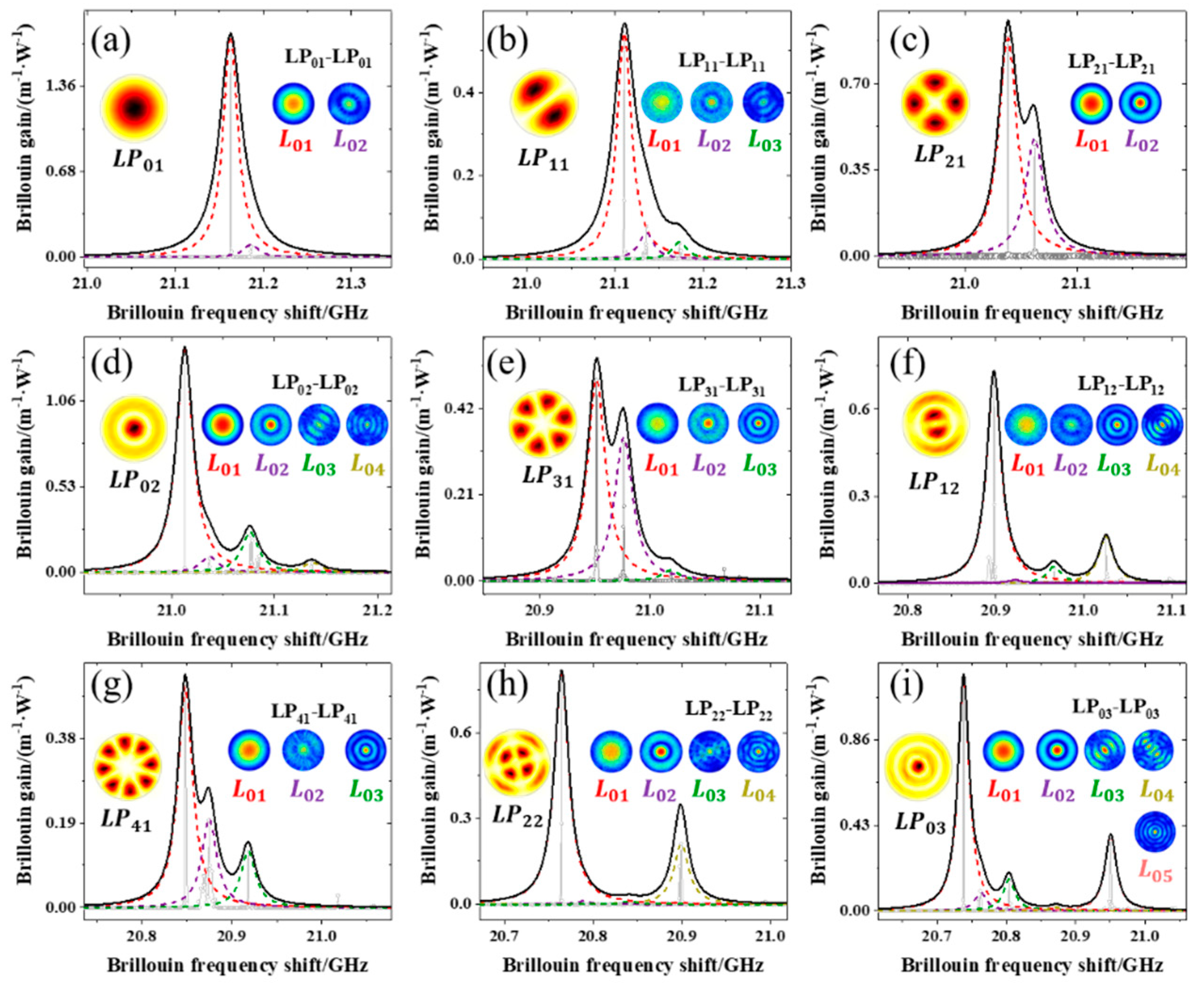
Figure 2a–i shows the simulated SBS BGS of nine LP 01 - LP 01 , LP 11 - LP 11 , LP 21 - LP 21 , LP 02 - LP 02 , LP 31 - LP 31 , LP 12 - LP 12 , LP 41 - LP 41 , LP 22 - LP 22 , and LP 03 - LP 03 pump and Stokes mode pairs. The BGS was calculated using Equation (6) and indicates the optical mode profile distribution for each mode pair and the acoustic mode profile distribution for each peak.
Figure 2 shows the BGS of the LP m n - LP m n pump and Stokes mode pairs; each curve corresponds to an acoustic mode L m n , and the spontaneous Brillouin spectrum of each acoustic mode is Lorentzian due to the exponential decay of the acoustic wave shape. We performed an appropriate Lorentzian curve fit for each peak in the BGS, and each BGS could fit a different number (1–5) of Lorentzian curves. It is worth noting that for BGS of all LP m n - LP m n pump and Stokes mode pairs, among all L m n acoustic modes corresponding to BGS, the peak value of L 0 n acoustic mode (m = 0) is dominant in all cases. This may be due to the fact that these acoustic modes are symmetric in intramodal SBS [31]. Another noteworthy point is the acoustic mode corresponding to the largest peak in all BGS, and the acoustic mode corresponding to the largest peak, is L 01 . This can be explained by the larger gain of the multimode SBS induced by the LP 01 mode.
The BFS is calculated by substituting n i and n j in Equation (4), and the acoustic mode velocity versus BFS for the intra-mode case is plotted in Figure 3.
Figure 3a shows the relationship between acoustic mode velocity and BFS for the nine interacting LP m n - LP m n pump and Stokes mode pairs. The line of each color represents an LP m n - LP m n optical mode pair, and each data point shape represents an L 0 n acoustic mode. Under the same acoustic mode ( L m n ), the lower-order optical mode corresponds to a larger BFS value. Under the optical mode pair ( LP m n - LP m n ), higher-order acoustic modes correspond to larger BFS values. Figure 3b demonstrates the intramode interaction corresponding to the pump and Stokes propagating in the LP 21 mode, showing the acoustic mode profiles of the symmetric and antisymmetric mode groups and their BFS values (data points denoted by stars sign). Obviously, higher-order acoustic modes correspond to larger BFS values.
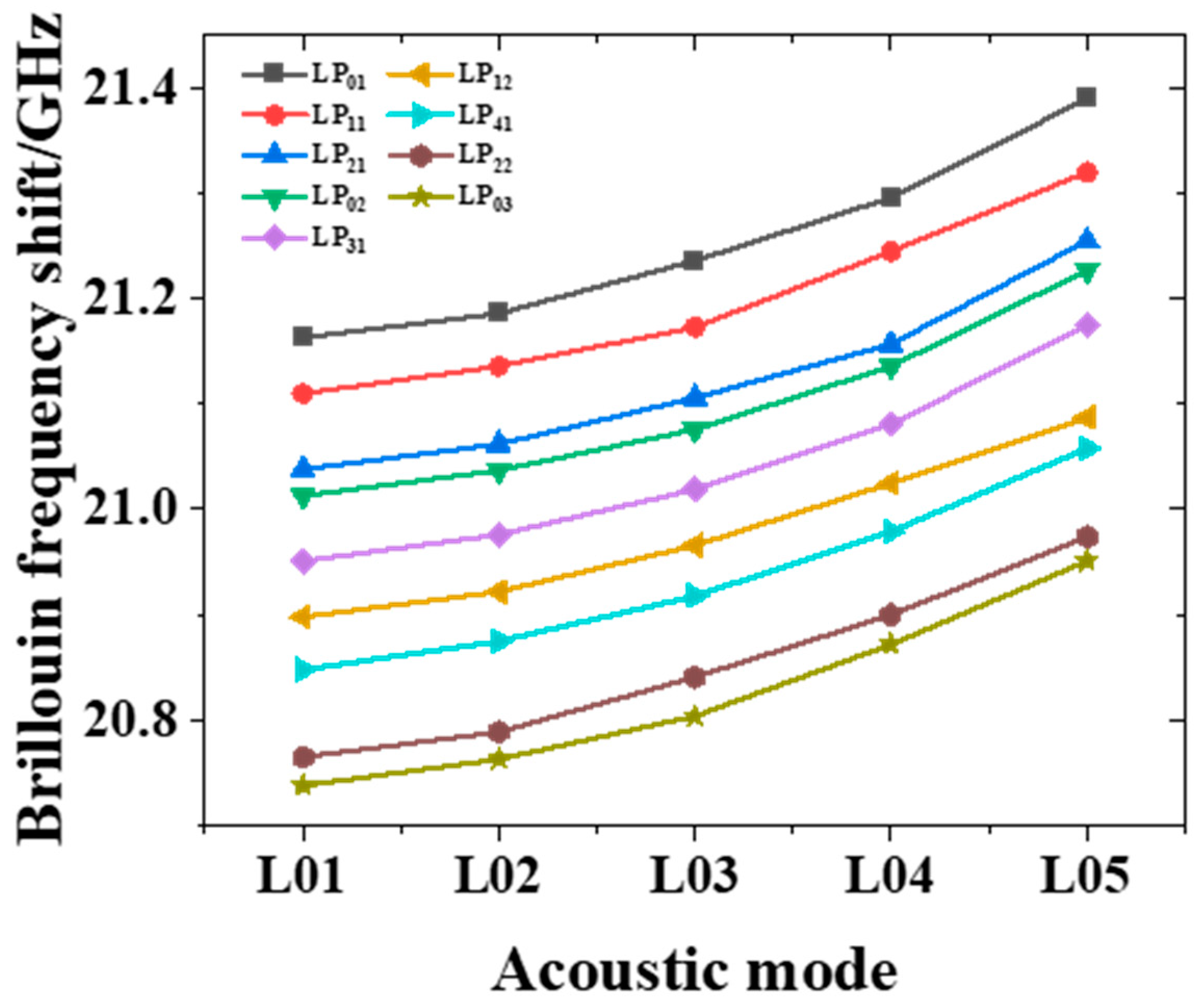
Figure 4 shows the BFS characteristics of the L 0 n acoustic mode for the nine LP m n - LP m n pump and Stokes mode pair interactions.
In Figure 4, v B varies in the range of 20.7–21.3 GHz, and the v B of the BGS peak of each mode decreases with the optical mode order and increases with the acoustic mode order. The specific variation in v B can be qualitatively explained by the smaller ERI of the higher-order optical modes and the larger acoustic velocity of the higher-order acoustic modes. Since the pump and Stokes mode interferograms are symmetric in intra-modal SBS, the BGS peaks can be attributed to symmetric acoustic modes such as L 01 , L 02 , L 03 , L 04 and L 05 [35].
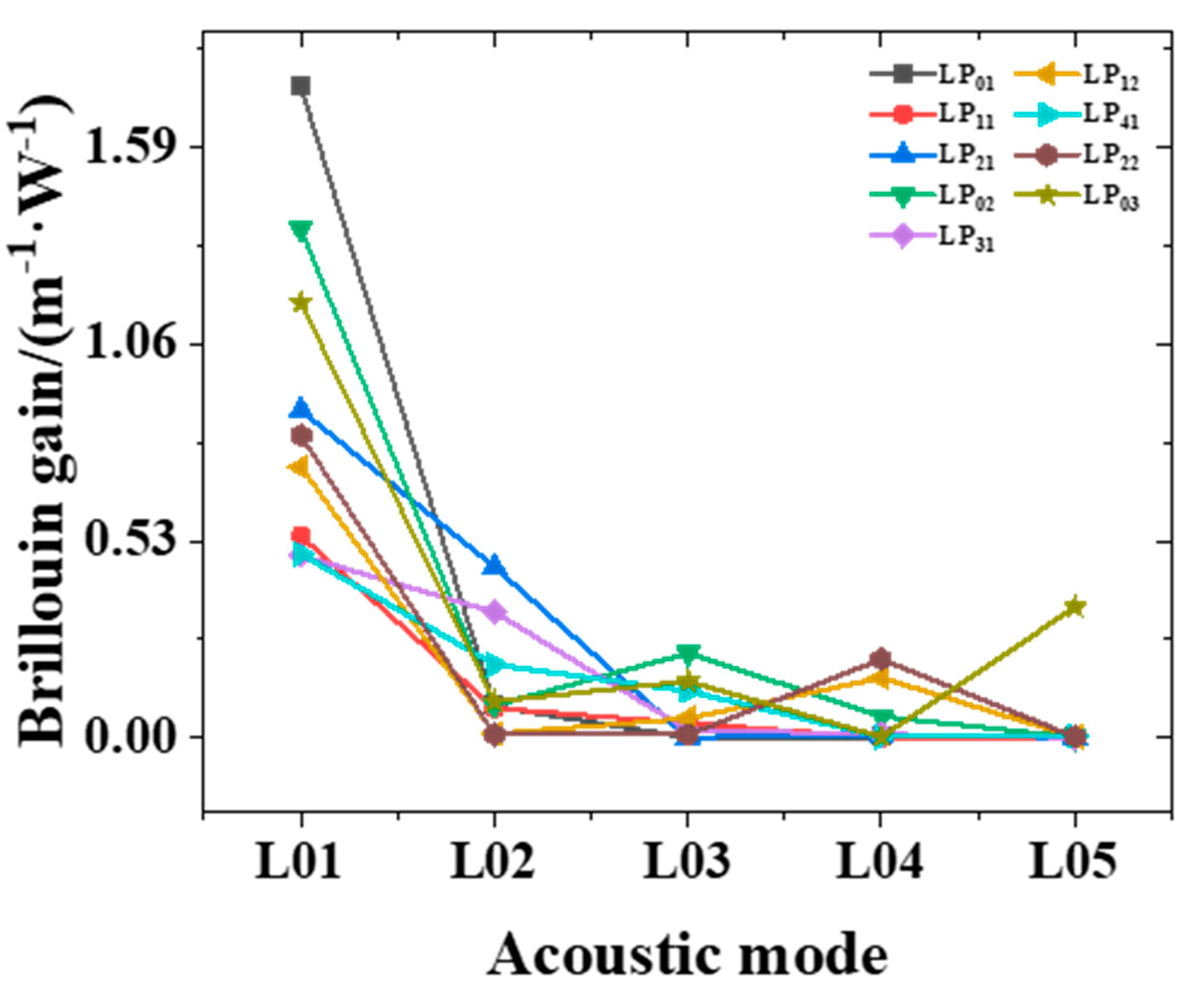
Figure 5 shows the Brillouin gain characteristics of the L 0 n acoustic mode for the nine LP m n - LP m n pump and Stokes mode pair interactions.
Figure 5 shows the relative amplitudes of the BGS peaks for each mode in multimode stimulated Brillouin scattering. In the case of each LP m n - LP m n mode pair, the Brillouin gain value of the L 01 acoustic mode under the LP 01 - LP 01 pump and Stokes mode pair is the largest, reaching 1.7525 m 1 · W 1 . The maximum peak ( L 01 acoustic mode) is several orders of magnitude larger than the other peaks, except for LP 21 , LP 31 , and LP 41 modes. The amplitude difference between the two main peaks is small, which is in the same order of magnitude.
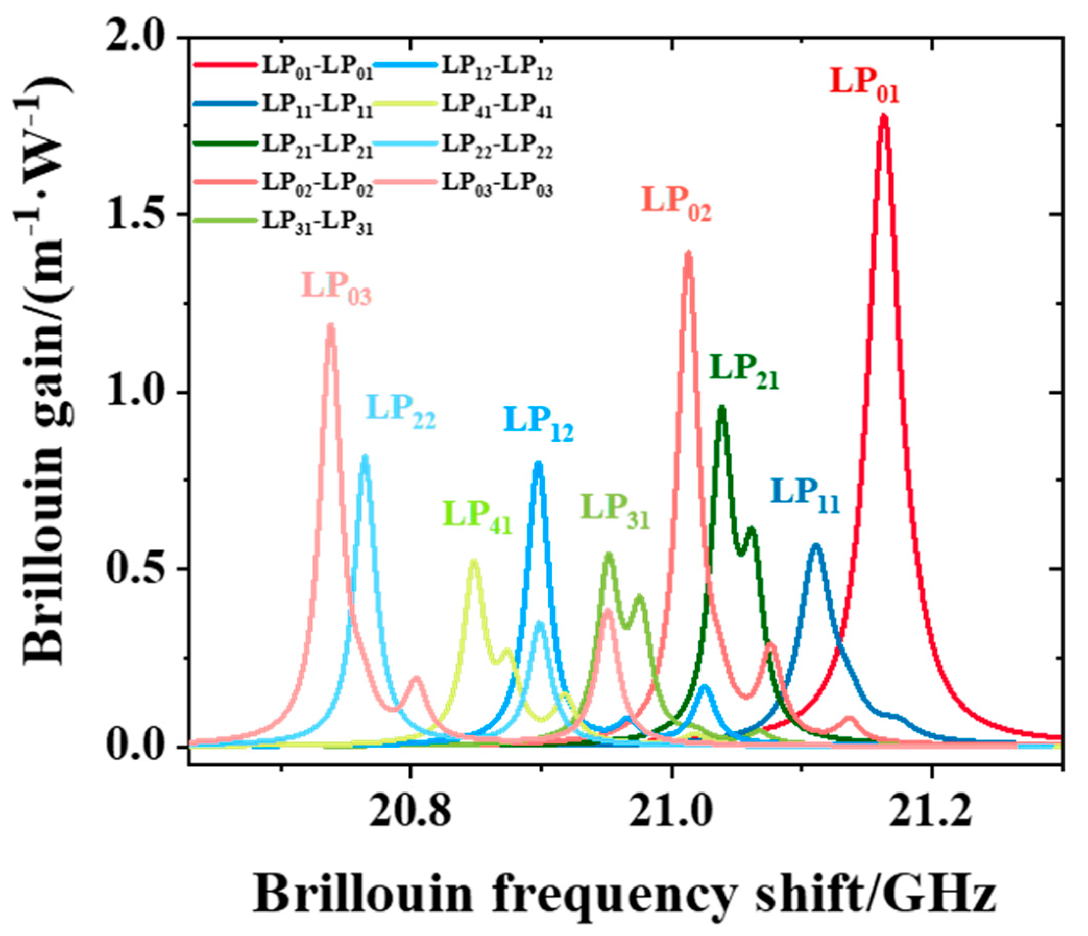
Figure 6 shows the total Lorentzian curve of each LP m n - LP m n mode pair BGS for the nine LP m n - LP m n pump and Stokes mode pair interactions.
It can be seen from Figure 6 that in the lithium niobate optical fiber, the BFS varies in the range of 20.7–21.3 GHz, and the highest Brillouin gain coefficient of each LP m n - LP m n mode pair is in the range of 4.9036E-1( LP 31 )-1.7525 ( LP 01 ) inside. The order of magnitude (GHz) of its own BFS is very high; in distributed sensing, the influence of changes in external parameters on BFS is usually mostly in the range of 100 MHz. The LP 01 , LP 02 , and LP 03 modes present a single main peak or a single main peak plus a small peak with a large difference in BFS. the LP 21 , LP 31 and LP 41 modes present two comparable peaks with a small difference in BFS, and the LP 11 , LP 12 , and LP 22 modes present a single main peak plus a small peak with a large difference in BFS. In the case of intramode SBS, the LP 01 mode provides the largest Brillouin gain, and according to the Lorentz peak distribution, we divide the nine modes into three groups: LP 01 , LP 02 , and LP 03 modes as the first group, LP 21 , LP 31 , and LP 41 modes as the second group, LP 11 , LP 12 , and LP 22 modes as the third group. The gain coefficient of the first group is generally higher, and the highest Brillouin gain coefficient of the second and third groups is about 50% of the LP 01 mode. This is attributable to the BGS cleavage observed in Figure 2.

4. Conclusions

In conclusion, this paper presents a new inorganic material lithium niobate as the transmission medium, and reports the Brillouin scattering properties of different pump–Stokes mode pairs in lithium niobate optical fibers, showing nine LP 01 - LP 01 , LP 11 - LP 11 , LP 21 - LP 21 , LP 02 - LP 02 , LP 31 - LP 31 , LP 12 - LP 12 , LP 41 - LP 41 , LP 22 - LP 22 , and LP 03 - LP 03 pump and Stokes mode pairs. We analyzed the L 0 m acoustic mode in the pump–Stokes mode pair in detail: the gain of the lithium niobate optical fiber BSBS reached 1.7525 m 1 · W 1 , and the frequency shift of Brillouin scattering in the range of 20.73–21.17 GHz was achieved, different from conventional silica. Lithium niobate is an anisotropic material. We plan to study the temperature and strain of lithium niobate optical fibers in future work, and carry out the fabrication of lithium niobate fiber and related experiments. We expect our design parameters to contribute to the optimization of Brillouin sensors and provide a new platform.

Author Contributions

Conceptualization, L.F. and Y.L.; methodology, L.F. and X.C.; software, L.F.; validation, L.F., X.C. and X.X.; writing—original draft preparation, L.F. and X.C.; writing—review and editing, L.F. and X.C.; visualization, W.H. and Y.Y.; supervision, L.W. and X.X. All authors have read and agreed to the published version of the manuscript.

Funding

This research was funded by the National Key R&D Program of China (2019YFF0301802); Key Research and Development (R&D) Projects of Shanxi Province (201903D121124); China Postdoctoral Science Foundation (2020M682113); Shanxi Scholarship Council of China (2020-112); Scientific and Technological Innovation Programs of Higher Education Institutions in Shanxi (2020L0268); Fundamental Research Program of Shanxi Province (20210302124390); Graduate Innovation Project of Shanxi Province (2021Y616); Fundamental Research Program of Shanxi (20210302124558).

Conflicts of Interest

The authors declare no conflict of interest.

References

  1. Eggleton, B.J.; Poulton, C.G.; Rakich, P.T. Brillouin integrated photonics. Nat. Photonics 2019, 13, 664–677. [Google Scholar] [CrossRef]
  2. Wolff, C.; Steel, M.J.; Eggleton, B.J. Stimulated Brillouin scattering in integrated photonic waveguides: Forces, scattering mechanisms, and coupled-mode analysis. Phys. Rev. A 2015, 92, 013836. [Google Scholar] [CrossRef] [Green Version]
  3. Zhu, Z.; Gauthier, D.J.; Boyd, R.W. Stored light in an optical fiber via stimulated Brillouin scattering. Science 2007, 318, 1748–1750. [Google Scholar] [CrossRef]
  4. Zhu, Z.; Dawes, A.M.C.; Gauthier, D.J. Broadband SBS slow light in an optical fiber. J. Lightw. Technol. 2007, 25, 201–206. [Google Scholar] [CrossRef] [Green Version]
  5. Zhang, R.; Sun, J. Design of Silicon Phoxonic Crystal Waveguides for Slow Light Enhanced Forward Stimulated Brillouin Scattering. J. Lightw. Technol. 2017, 35, 2917–2925. [Google Scholar] [CrossRef]
  6. Willner, A.E.; Zhang, B.; Zhang, L. Optical signal processing using tunable Delay elements based on slow light. IEEE J. Sel. Top. Quantum Electron. 2008, 14, 691–705. [Google Scholar] [CrossRef]
  7. Deng, D.; Gao, W.; Cheng, T. Highly Efficient Fast Light Generation in a Tellurite Fiber Embedded in Brillouin Laser Ring Cavity. IEEE Photonics Technol. Lett. 2014, 26, 1758–1761. [Google Scholar] [CrossRef]
  8. Pant, R.; Byrnes, A.; Poulton, C.G. Photonic-chip-based tunable slow and fast light via stimulated Brillouin scattering. Opt. Lett. 2012, 37, 969–971. [Google Scholar] [CrossRef]
  9. Zhang, W.; Minasian, R.A. Widely Tunable Single-Passband Microwave Photonic Filter Based on Stimulated Brillouin Scattering. IEEE Photonics Technol. Lett. 2011, 23, 1775–1777. [Google Scholar] [CrossRef]
  10. Marpaung, D.; Morrison, B.; Pagani, M. Low-power, chip-based stimulated Brillouin scattering microwave photonic filter with ultrahigh selectivity. Optica 2015, 2, 76–83. [Google Scholar] [CrossRef]
  11. Minasian, R.A.; Chan, E.H.W.; Yi, X. Microwave photonic signal processing. Opt. Express 2013, 21, 22918–22936. [Google Scholar] [CrossRef] [PubMed]
  12. Choudhary, A.; Morrison, B.; Aryanfar, I. Advanced Integrated Microwave Signal Processing With Giant On-Chip Brillouin Gain. J. Lightw. Technol. 2017, 35, 846–854. [Google Scholar] [CrossRef]
  13. Horiguchi, T.; Shimizu, K.; Kurashima, T. Development of a Distributed Sensing Technique Using Brillouin Scattering. J. Lightw. Technol. 1995, 13, 1296–1302. [Google Scholar] [CrossRef]
  14. Hotate, K.; Ong, S.S.L. Distributed dynamic strain measurement using a correlation-based Brillouin sensing system. IEEE Photonics Technol. Lett. 2003, 15, 272–274. [Google Scholar] [CrossRef]
  15. Kittlaus, E.A.; Otterstrom, N.T.; Rakich, P.T. On-chip inter-modal Brillouin scattering. Nat. Commun. 2017, 8, 15819. [Google Scholar] [CrossRef]
  16. Merklein, M.; Casas-Bedoya, A.; Marpaung, D. Stimulated Brillouin Scattering in Photonic Integrated Circuits: Novel Applications and Devices. IEEE J. Sel. Top. Quantum Electron. 2016, 22, 336–346. [Google Scholar] [CrossRef]
  17. Ippen, E.P.; Stolen, R.H. Stimulated Brillouin scattering in optical fibers. Appl. Phys. Lett. 1972, 21, 539–541. [Google Scholar] [CrossRef]
  18. Kobyakov, A.; Sauer, M.; Chowdhury, D. Stimulated Brillouin Scattering in Optical Fibers. Adv. Opt. Photonics 2009, 2, 1–59. [Google Scholar] [CrossRef]
  19. Hill, K.O.; Kawasaki, B.S.; Johnson, D.C. cw Brillouin laser. Appl. Phys. Lett. 1976, 28, 608–609. [Google Scholar] [CrossRef]
  20. Essiambre, R.J.; Kramer, G.; Winzer, P.J. Capacity Limits of Optical Fiber Networks. J. Lightw. Technol. 2010, 28, 662–701. [Google Scholar] [CrossRef]
  21. Eggleton, B.J.; Poulton, C.G.; Pant, R. Inducing and harnessing stimulated Brillouin scattering in photonic integrated circuits. Adv. Opt. Photonics 2013, 5, 536. [Google Scholar] [CrossRef]
  22. Song, K.Y.; Kim, Y.H. Characterization of stimulated Brillouin scattering in a few-mode fiber. Opt. Lett. 2013, 38, 4841–4844. [Google Scholar] [CrossRef]
  23. Li, A.; Hu, Q.; Shieh, W. Characterization of stimulated Brillouin scattering in a circular-core two-mode fiber using optical time-domain analysis. Opt. Express 2013, 21, 31894–31906. [Google Scholar] [CrossRef] [PubMed]
  24. Li, A.; Wang, Y.; Hu, Q. Few-mode fiber based optical sensors. Opt. Express 2015, 23, 1139–1150. [Google Scholar] [CrossRef] [PubMed]
  25. Xu, Y.; Ren, M.; Lu, Y. Multi-parameter sensor based on stimulated Brillouin scattering in inverse-parabolic graded-index fiber. Opt. Lett. 2016, 41, 1138. [Google Scholar] [CrossRef] [PubMed]
  26. Zhou, X.; Guo, Z.; Ke, C. Simultaneous temperature and strain sensing utilizing Brillouin frequency shifts contributed by multiple acoustic modes. In Proceedings of the IEEE 2016 IEEE Photonics Conference (IPC), Waikoloa, HI, USA, 2–6 October 2016; pp. 817–818. [Google Scholar]
  27. Fang, J.; Milione, G.; Stone, J. Multi-parameter distributed fiber sensing with higher-order optical and acoustic modes. Opt. Lett. 2019, 44, 1096. [Google Scholar] [CrossRef] [PubMed]
  28. Kim, Y.H.; Song, K.Y. Recent Progress in Distributed Brillouin Sensors Based on Few-Mode Optical Fibers. Sensors 2021, 21, 2168. [Google Scholar] [CrossRef]
  29. Qi, Y.; Li, Y. Integrated lithium niobate photonics. Nanophotonics 2020, 9, 1287–1320. [Google Scholar] [CrossRef]
  30. Lin, J.; Bo, F.; Cheng, Y. Advances in on-chip photonic devices based on lithium niobate on insulator. Photonics Res. 2020, 8, 1910–1936. [Google Scholar] [CrossRef]
  31. Wang, J.-S.; Tseng, Y.-H. ITO electrode-embedded double-cladding single-crystal LiNbO3 optical fiber. Opt. Lett. 2013, 38, 452–454. [Google Scholar] [CrossRef]
  32. Russell, P.S.J.; Culverhouse, D. Experimental observation of forward stimulated Brillouin scattering in dual-mode single-core fibre. Electron. Lett. 1990, 26, 1195–1196. [Google Scholar] [CrossRef]
  33. Beugnot, J.C.; Sylvestre, T.; Maillotte, H.; Melin, G.; Laude, V. Guided acoustic wave Brillouin scattering in photonic crystal fibers. Opt. Lett. 2007, 32, 17–19. [Google Scholar] [CrossRef] [PubMed] [Green Version]
  34. Qiu, W.; Rakich, P.T.; Shin, H. Stimulated Brillouin scattering in nanoscale silicon step-index waveguides: A general framework of selection rules and calculating SBS gain. Opt. Express 2013, 21, 31402–31419. [Google Scholar] [CrossRef] [PubMed] [Green Version]
  35. Jen, C.K.; Safaai-Jazi, A.; Farnell, G.W. Leaky Modes in Weakly Guiding Fiber Acoustic Waveguides. IEEE Trans. Ultrason. Ferroelectr. Freq. Control 1986, 33, 634–643. [Google Scholar]
Figure 1. Schematic diagram of Brillouin scattering in lithium niobate optical fiber, the distribution of LP 01 , LP 11 , and LP 21 optical modes in the core region, and the distribution of L 01 , L 11 , and L 21 acoustic modes in the core and cladding regions.
Applsci 12 06476 g001
Figure 2. BGS of different pairs of pump-probe modes in the FMF: (a) LP 01 - LP 01 ; (b) LP 11 - LP 11 ; (c) LP 21 - LP 21 ; (d) LP 02 - LP 02 ; (e) LP 31 - LP 31 ; (f) LP 12 - LP 12 ; (g) LP 41 - LP 41 ; (h) LP 22 - LP 22 ; and (i) LP 03 - LP 03 modes.
Applsci 12 06476 g002
Figure 3. (a) The relationship between the BFS of the mode and the velocity of acoustic for the nine intramodes. (b) The acoustic mode profile under the LP 21 - LP 21 mode pair is shown as an inset, corresponding to the relationship between the velocity of acoustic and the BFS of the ten acoustic modes.
Applsci 12 06476 g003
Figure 4. BFS characteristics of L 0 n acoustic mode in the case of nine LP m n - LP m n mode pairs.
Applsci 12 06476 g004
Figure 5. Brillouin gain characteristics of the L 0 n acoustic mode in the case of nine LP m n - LP m n mode pairs.
Applsci 12 06476 g005
Figure 6. In the case of nine LP m n - LP m n mode pairs, the total Lorenz curve of each LP m n - LP m n mode pair to BGS.
Applsci 12 06476 g006
Table 1. Structure and material parameters for the SIF.
Values
ParametersCoreCladding
Radius (μm) r core = 4.5 r clad = 20
Refractive index n core = 2.245 n clad = 1.45
Mass   density   ( kg / m 3 ) ρ core = 4700 ρ clad = 2203
Longitudinal acoustic velocity (m/s) V l core = 7318 V lclad = 5950
Photo-elastic coefficients p 11 = 0.02 , p 12 = 0.08 , p 44 = 0.12
Transmission loss at 1550 nm (dB/cm) a0.89
a Ref. [31].
Table 2. Optical mode parameters.
Mode L P 01 L P 11 L P 21 L P 02 L P 31 L P 12 L P 41 L P 22 L P 03
Effective refractive index 2.2413 2.2358 2.2281 2.2254 2.2189 2.2132 2.208 2.1991 2.1963
Publisher’s Note: MDPI stays neutral with regard to jurisdictional claims in published maps and institutional affiliations.