Article

A MIG Welding Clamping Scheme for Power Battery Enclosure’s Deformation Restrain

School of Mechanical and Electrical Engineering, Wuhan University of Technology, Luoshi Road 122, Wuhan 430070, China
*
Author to whom correspondence should be addressed.
Appl. Sci. 2022, 12(13), 6598; https://doi.org/10.3390/app12136598
Submission received: 1 June 2022 / Revised: 22 June 2022 / Accepted: 25 June 2022 / Published: 29 June 2022
(This article belongs to the Section Mechanical Engineering)

Abstract

:
Aiming at the inward shrinkage between the frame and the bottom plate of the power battery enclosure after MIG (melt inert-gas) welding, a welding clamping scheme with hook-pull devices was designed. By adjusting the clamping force of the hook-pull device, the MIG welding deformation force was counteracted, so the inward shrinkage deformation of the frame after welding was restrained. To obtain the deformation force during the MIG welding, the welding simulation model of power battery enclosure was established. Gaussian heat source model was selected as temperature load. Through the numerical simulation and experimental analysis of the temperature field, the numerical simulation results are in good agreement with the measured thermal cycle curve in terms of temperature value and change trend. The error between numerical simulation result curve and measured thermal cycle curve at the measurement point is no more than 10%, which can meet the simulation requirements. Based on the simulation model and the load of the temperature field, deformation force curves were obtained by simulating the welding process. To counteract the MIG welding deformation force, a pneumatic servo control system of the welding clamp was designed, which can generate equal and reversed welding deformation force. The experiments show that the actual output force of the system has a tiny time delay and fluctuates with the varies of the pneumatic servo control system. The maximum fluctuation error is 6.96 N, which is within the permitted error range. The welding experiments were carried out to verify effectiveness of the control system and the welding clamp. The field results have shown that the maximum inward shrinkage deformation after welding is 0.6 mm, which is less than 1.2 mm required by the MIG welding process.

1. Introduction

To face with the problems of environmental pollution and energy shortage, the world’s major automobile industry countries have taken the new energy automobile industry as a core strategy in strategic choice. As the core component of a new energy vehicle, the power battery system mainly consists of power battery cooling module, battery management module, and power battery enclosure. The power battery enclosure is specially designed for accommodating more batteries to increase the cruising range, so its structure size is large. To fulfill the requirement of lightweight design, it is usually made of aluminum alloy. In its welding manufacture process, due to the large thermal expansion coefficient, good thermal conductivity and fast heat dissipation rate of the aluminum alloy, the long fillet weld between the enclosure bottom plate and the frame is prone to large welding deformation during MIG welding. Excessive welding deformation will have a great impact on the welding between the lifting lug and the side of the frame. In serious cases, it would lead to failure of welding.
In terms of the numerical simulation of welding, Yamakawa et al. [1] proposed a method to analyze the thermal stress and residual stress in the welding process based on the finite element method and the thermal elastoplastic model, which makes it possible to quantify the stress and deformation in the welding process. Okumoto et al. [2] proposed an intrinsic strain method to improve computing efficiency of the thermoelastic-plastic finite element method for large components and complex structures. Bachorski et al. [3] proposed a shrinkage volume method for large and complex structural welded members, which can quickly predict the welding deformation by linear elastic finite element method. Spina [4] adopted the finite element method to simulate the laser welding process of aluminum alloy sheets and predict the welding deformation. Piekarska et al. [5] used ABAQUS software to simulate the welding thermal process of two butted stainless-steel plates. The results showed that the largest deformation after welding appeared in the weld area, which was in good agreement with the actual measured welding deformation. Based on theory of thermoelastic finite element, Lu et al. [6] established a series of key techniques for the accuracy and computational efficiency of the numerical simulation of the welding stress-strain field. Li et al. [7] applied numerical simulation technique to simulate and predict the welding deformation of the aluminum alloy car body sheet manufactured by MIG welding. Compared with the measured deformation results, the error was within 20%. Cai et al. [8] proposed a thermo-elastic-plastic finite element calculation method to simulate multi-layer multi-pass welding. The stress-strain fields of butt joints with various grooves were simulated. Accuracy of calculation method was verified by the test results. Chen et al. [9] conducted sensitivity analysis on MIG welding parameters using response surface method. The calculation shows that the welding current and the welding speed have the most significant effect during the MIG welding of SUS301L-HT stainless steel, while the arc voltage has a relatively weak effect on the welding. Z Samad [10] investigated the effect of heat input and welding speed on the weld pool shape and temperature distribution. The finite element code, ANSYS along with APDL command subroutines was employed to obtain the numerical results. The result shows that the predicted temperature distribution and the size of heat-affected zone are in good agreement. Lei et al. [11] found out the effect of different welding methods on the residual stress distribution by means of neutron diffraction measurements and FE model simulation. Results show that residual stresses of MIG welding process are higher than those of friction stir welding process.
This paper focuses on solving the deformation problem during MIG welding between the bottom plate and frame of power battery enclosure. In Section 1, by analyzing the product structure and processing requirements on power battery enclosure, a pneumatic clamp scheme with hook-pull devices was designed to restrain the welding deformation. In Section 2, the clamping force curves required to restrain the welding deformation were obtained by simulating the power battery enclosure’s welding process. In Section 3, a pneumatic servo control system of MIG welding clamp was designed. The pneumatic circuit simulation model of the control system was built by using AMESim software, and it was co-simulated with the clamping force controller model, which was modeled by MATLAB. In Section 4, a test scheme for dynamic adjustment of clamping force was designed to verify whether the pneumatic servo control system can generate the clamping force to suppress the deformation force or not. Furthermore, effectiveness of the clamping scheme was verified by field welding experiment.
The main innovations of this paper are as follows. To restrain the welding deformation between the bottom plate and the frame of the power battery enclosure, a clamping scheme with hook-pull devices is proposed. The scheme uses the clamping force generated by the welding fixture to offset the welding deformation force, realizes the clamping function and suppresses the welding deformation at the same time. To realize the clamping scheme, the numerical simulation analysis of MIG welding process is carried out to obtain the reaction force required to restrain welding deformation. Finally, to restrain welding deformation, a pneumatic servo control system is designed. In the process of MIG welding, the servo system controls the hook-pull device to generate clamping forces to restrain welding deformation.

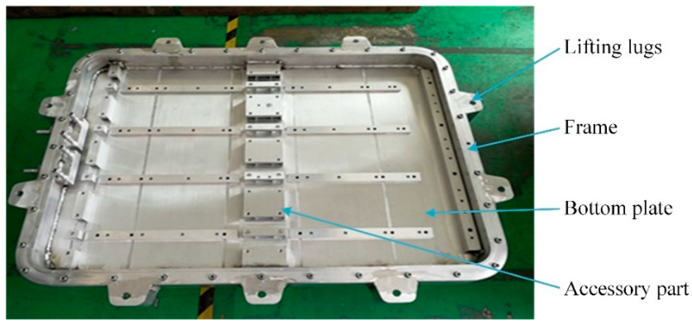
2. The MIG Welding Clamping Scheme of Power Battery Enclosure

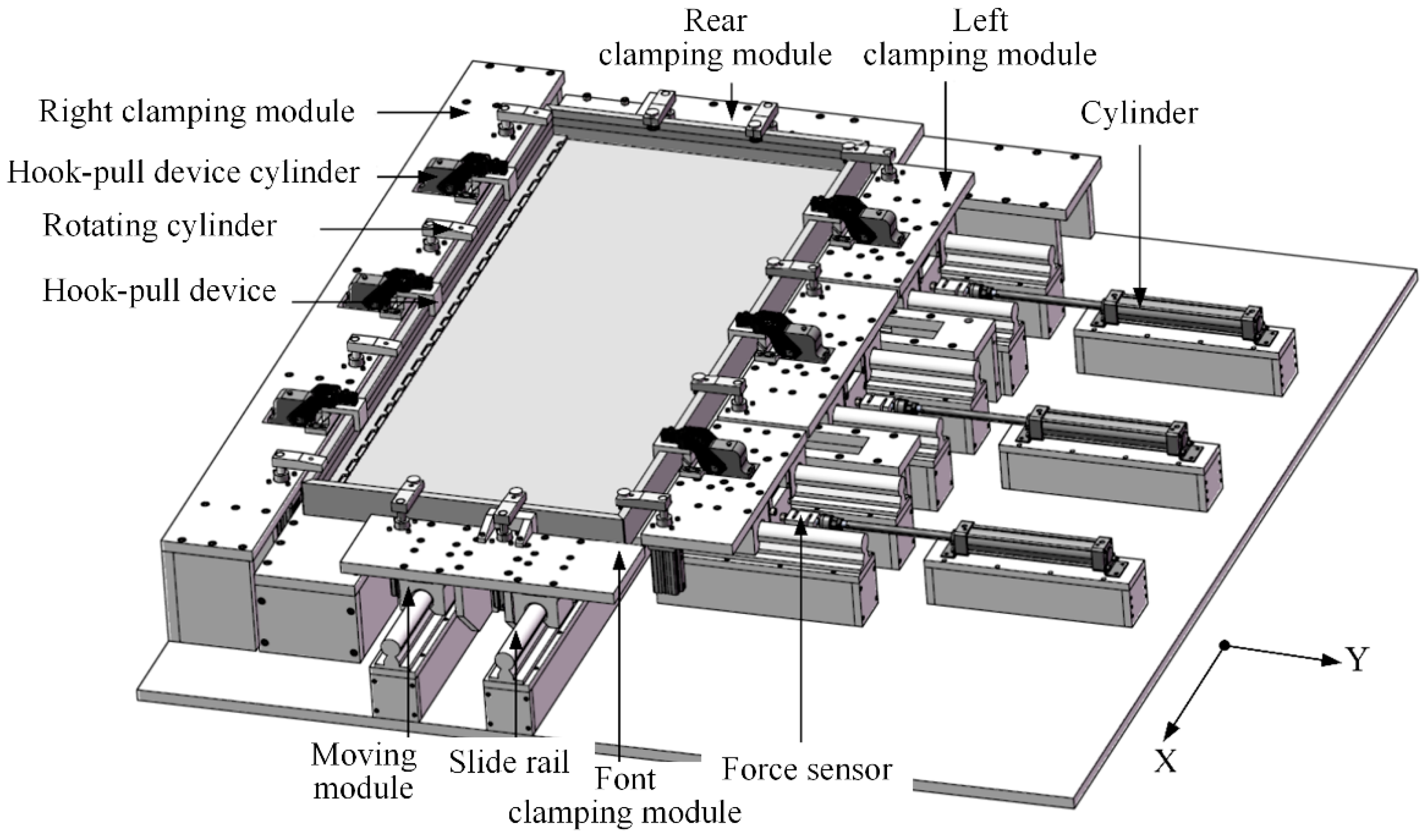
2.1. Design of Positioning and Clamping Scheme

The power battery enclosure is made of aluminum alloy by welding. It is mainly composed of the bottom plate, frame, lifting lugs, and other accessories, as shown in Figure 1. After fixing the bottom plate and the frame through spot welding, MIG welding is carried out to make the frame and the bottom plate become a whole.
According to the processing requirements on power battery enclosure, the inward shrinkage of crossbeams on each side will severely affect installation of the lifting ears if the value exceed 1.2 mm. Therefore, the welding deformation of the crossbeams on both sides of the power battery enclosure need to be restrained by adjusting clamping force of the welding clamp to meet the processing requirements. The overall structural size of the power battery enclosure investigated in this paper is 1900 mm × 850 mm × 92 mm, and the frame height is 20 mm. As shown in Figure 2, the whole clamping scheme was divided into four modules to facilitate analysis, which is shown in Figure 2.
In order to meet the requirements on clamping, a rotating clamping cylinder and a clamping module driven by cylinder was adopted to realize the clamping in Z and X direction respectively. In Y direction, cylinders were used to drive the hook-pull devices on clamping modules of the crossbeams to move reversely, forming a reverse hook tension to realize the clamping effect. After the enclosure was clamped, the output clamping force of the driving cylinder can be dynamically adjusted according to the welding deformation force, so as to counteract the welding force to effectively restrain the welding deformation without damaging the workpiece.

2.2. Design of Positioning and Clamping Scheme

Bottom plate of the power battery enclosure has the characteristics of a large-area plane in the bottom and long straight planes on surrounding sides. Therefore, the surface of the bottom plate was selected as the main positioning reference plane, the inner surface of the right crossbeam was used as the guiding positioning reference plane. Moreover, outer surface of the rear crossbeam was selected as the thrust reference plane. Three positioners were used to locate the main positioning reference positioning plane according to six-point positioning principle. The welding deformation on both side crossbeams of the power battery enclosure should be restrained. The guide-localization datum surface was positioned with three positioners to improve clamping stability. The thrust reference plane was positioned by one positioner.
Comprehensively considering the positioning reference and the direction of external force, action direction of clamping force of the power battery enclosure was determined as follows. The clamping force in the X-direction acts on the positioning reference pointing to the X-direction (i.e., rear crossbeam of the power battery enclosure), the clamping mode of the hook-pull was adopted in the Y-direction, and the clamping force was directed to left crossbeam of the power battery enclosure, so as to realize clamping in the Y direction and restrain welding deformation, clamping force in the Z-direction points to the main positioning datum, namely the bottom plate of the power battery enclosure. The clamping force is consistent with the gravity direction, which can ensure that the required clamping force can be reduced on the premise of reliable clamping.

3. Simulation Analysis of Clamping Scheme

3.1. Simulation Preprocess

In order to obtain the clamping force required to restrain welding deformation, the thermal coupling analysis of MIG welding process of power battery enclosure was carried out by adopting the multi field-physical analysis method of ANSYS. The mesh module in ANSYS was adopted to mesh the simplified geometric model of power battery enclosure. Number of the grids is 296,611, and the average grid quality is 0.88. Processing base material of the power battery enclosure is 6005A aluminum alloy, and its thermophysical performance parameters were shown in Figure 3.
In the process of numerical simulation, the thermal mechanical coupling analysis of welding belongs to a complex and nonlinear problem, and the nonlinear change of material parameters with temperature makes the numerical simulation solution difficult to converge. Therefore, the following assumptions for the simulation process of MIG welding are made. The heat conduction between the power battery enclosure and the clamping elements is not considered. The heat conduction between the power battery enclosure and the clamp is ignored and assumed that all outer boundaries of the power battery enclosure only conduct convective heat transfer and radiation heat transfer with the surrounding environment. The inconsistency between the welding base metal and welding wire material of the power battery enclosure is ignored and unified as the thermophysical performance parameters of the base metal.

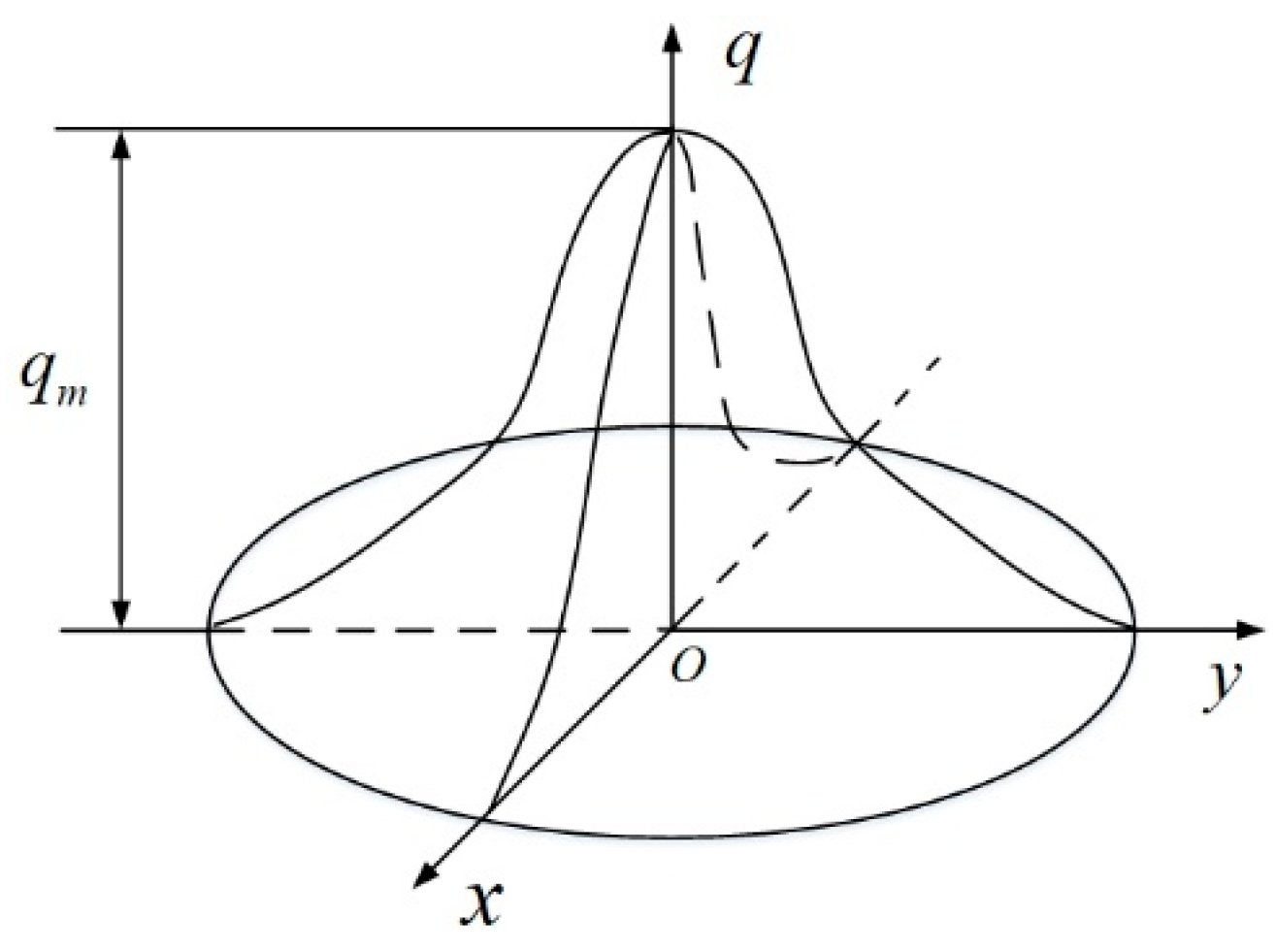
3.2. Heat Source Model Selection and Verification

3.2.1. Heat Source Model Selection

Welding profile of the power battery enclosure is aluminum alloy sheet, and its thickness is between 2 mm and 3 mm, which has led to a shallow molten pool during welding. Therefore, the use of Gaussian heat source in welding can not only obtain more accurate numerical simulation results but also have the advantages of high calculation efficiency and short calculation time [12], compared with the double ellipsoid heat source. The selected Gaussian heat source model is shown in Figure 4.
Gaussian heat source model is a typical distributed heat source model. During welding process, the arc heat source transfers heat to welding components through heating spots with a certain action area, and its heat flux can be described by Gaussian normal distribution function, as shown in Formula (1).
q ( r ) = Q 2 π σ q 2 e ( r 2 2 σ q 2 )
where, q ( r ) is the heat flux density at position r from the center of the heating spot, J / ( mm 2 s ) ; Q is the effective thermal power of the arc, Q = η U I , W ; η is the welding thermal efficiency; σ q is the Gaussian heat source distribution parameter; r is the distance from the center of the heating spot, mm .

3.2.2. Verification of Heat Source Model

During thermodynamic coupling simulation process, the numerical simulation result of temperature field acted as the input load of subsequent thermal elastic-plastic analysis. In order to ensure that the simulation results are closer to reality, the temperature field simulation analysis is needed to verify the correctness of the temperature field load. To get the temperature of specific points during temperature field analyzing, the measurement points were arranged at the center of the short side weld and the long side weld of the power battery enclosure. The thermal cycle curves of the specified points were extracted using the thermocouple temperature measurement system. The curves were used to correct the heat source model, Figure 5 depicts heat cycle curves for the experimental and the modified numerical simulation result. The error between numerical simulation result curve and measured thermal cycle curve at the measurement point is no more than 10%, which can meet the simulation requirements.

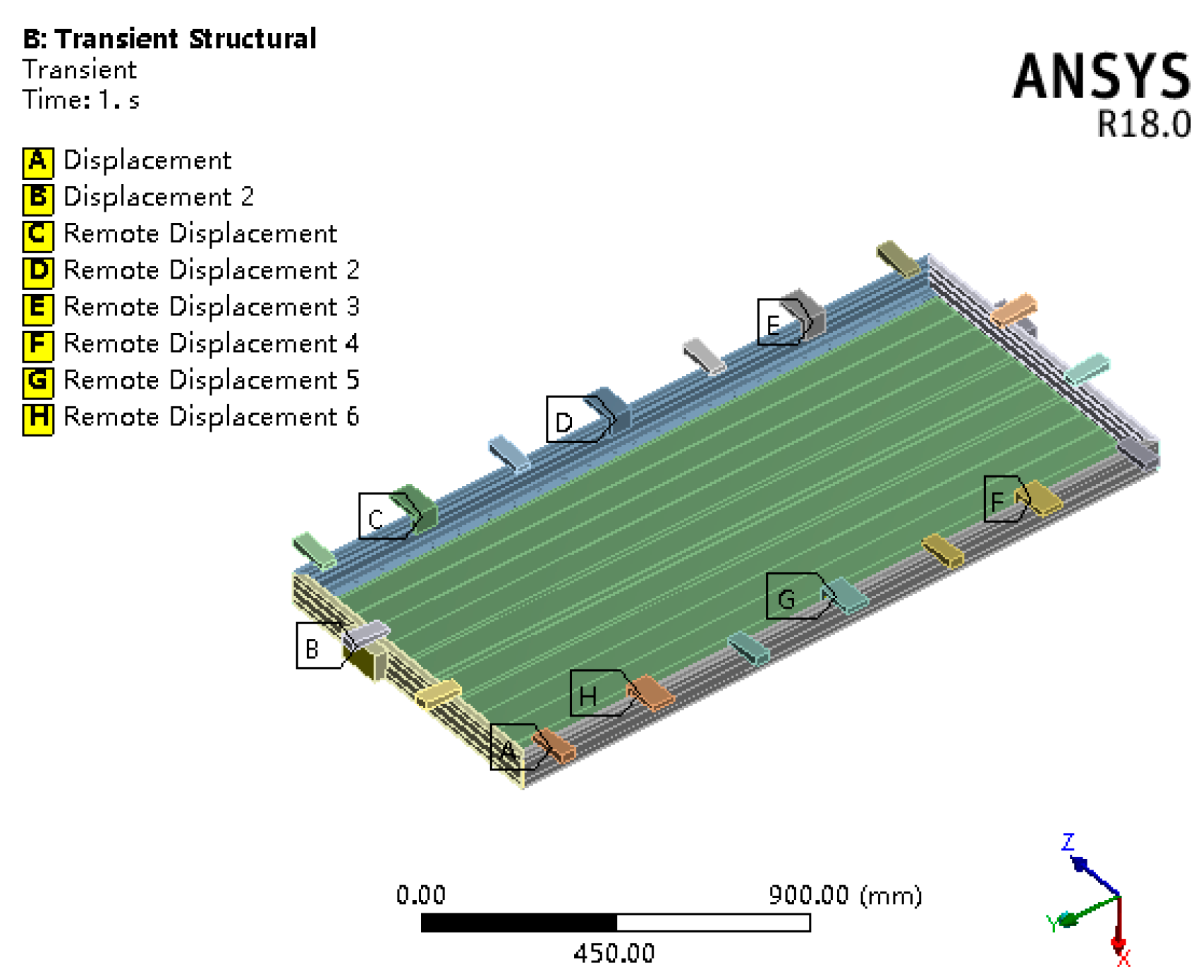
3.3. Boundary Conditions and Simulation Results

3.3.1. Boundary Conditions

The power battery enclosure is usually welded in a well-ventilated normal temperature environment. Therefore, in the thermal coupling numerical simulation, the initial conditions were set as follows: workpiece temperature T = 20 °C, welding environment temperature T0 = 20 °C. In the welding process, with the uniform movement of the welding gun, there are convective heat transfer and radiation heat transfer processes between the workpiece and the surrounding environment [13], resulting in a gradual reduction of the heat source intensity at the original position. Therefore, an accurate heat transfer boundary condition is essential for numerical simulation of the whole welding process. After many experiments, it is finally determined that the convective heat transfer coefficient h is 20 W/(m2·K) and the radiation blackness ε is 0.6, the other welding parameters are shown in Table 1.
In order to obtain the welding deformation force curve, the constraint mode at the clamping position of the crossbeams on both sides of the power battery enclosure was set as the distal displacement constraint, and the displacement in the deformation direction of the crossbeams on both sides of the power battery enclosure was limited, as shown in Figure 6.

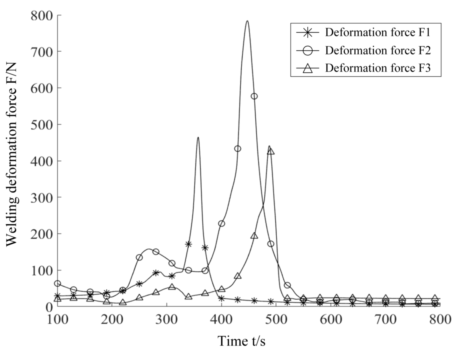
3.3.2. Simulation Results

Through simulation analysis of the model, the welding deformation force curve of the crossbeam on both sides of the power battery enclosure was obtained, as shown in Figure 7, in which the deformation forces on the left and right sides are similar. With the progress of MIG welding, deformation force at the three restrain positions on the crossbeam reaches the maximum in turn and then gradually decreases.
The main reason for the change of welding deformation force is the movement of welding heat source. The welding heat source approaches the constraint position, resulting in the gradual increase of deformation force, which reaches the maximum value at the constraint position. When the welding heat source approaches the constraint position, deformation force gradually increases and reaches the maximum value at the constraint position. Then, the deformation force decreases with the distance of the welding heat source gradually increasing. Since the restrain positions are evenly distributed on the crossbeams on both sides, the peak values of the deformation force F1 and F3 at the restrain positions at both ends are similar and less than the deformation force F2 at the middle restrain position. It is consistent with the result that the deformation of the crossbeam near both ends is small, and the deformation of the middle part is large in actual production.

4. Servo Control System Design and Simulation Analysis

4.1. Servo Control System

In order to restrain welding deformation, it is necessary to control clamping force of the hook-and-pull device. Therefore, ITV3050 electric proportional valve was adopted to build a clamping force servo control system, as shown in Figure 8. In the control system, the actuator is a single rod double acting cylinder, and the measuring element is a force sensor. The control system adjusts the pressure of the rod cavity and rodless cavity of the driving cylinder respectively through two electric proportional valves to accurately adjust the clamping force of the hook-and-pull device. Since the pneumatic servo system is a nonlinear time-varying system, the fuzzy adaptive PID control algorithm was applied to accurately and stably adjust clamping force of the crossbeam on both sides during the welding process.

4.2. Servo Control System

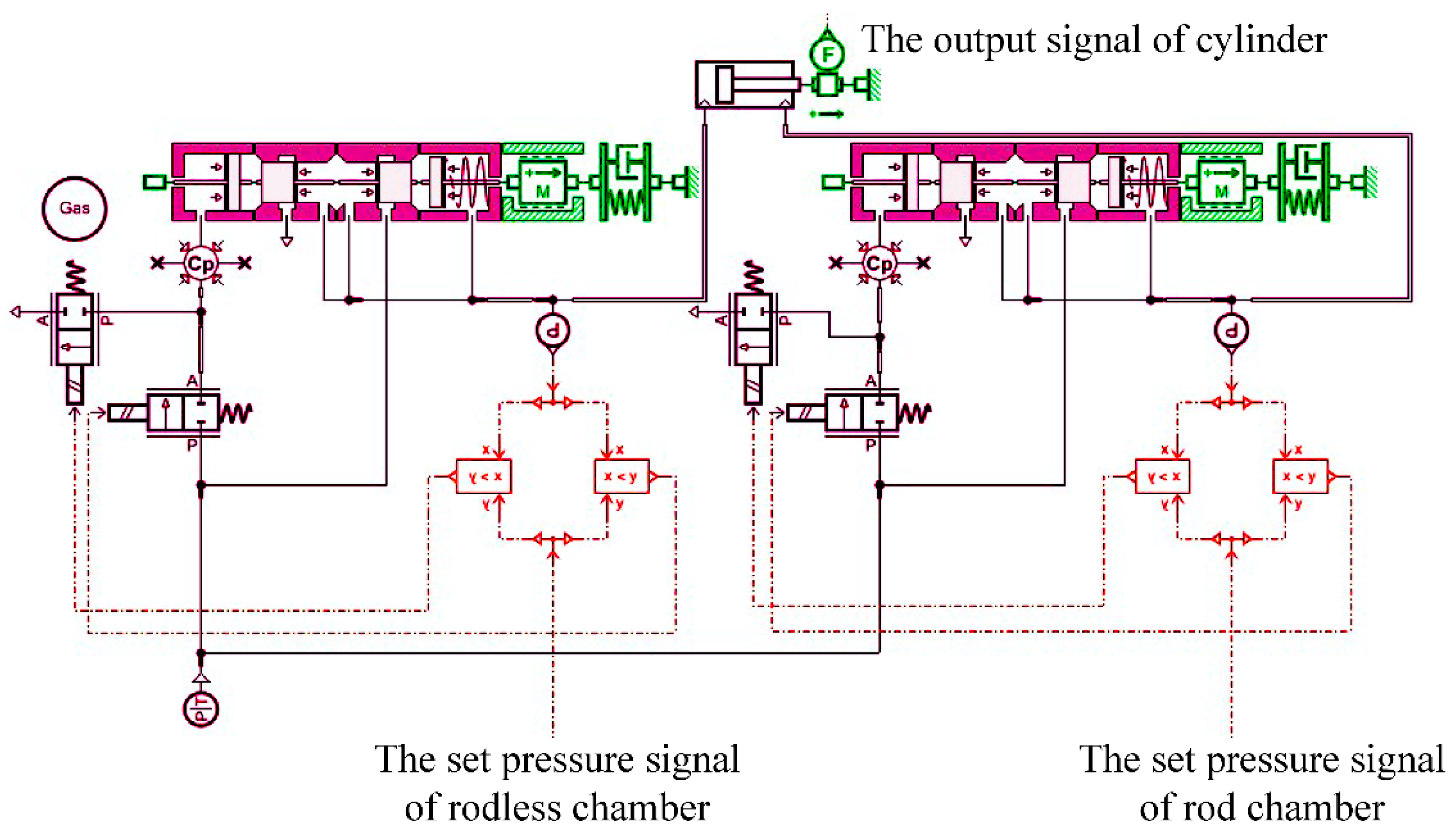
4.2.1. Pneumatic Circuit Modeling

In order to verify feasibility of the pneumatic servo control system, an AMESim simulation model of the control system was established according to the working principle of the pneumatic servo control system, as shown in Figure 9. The AMESim simulation model consists of two electric proportional valve models and a single rod double acting cylinder model. In the simulation model, the pressure of the rod and the rodless cavity is controlled by two electric proportional valves. Output force of the cylinder was taken as the feedback signal. Simulation parameters of electric proportional valve are shown in Table 2.

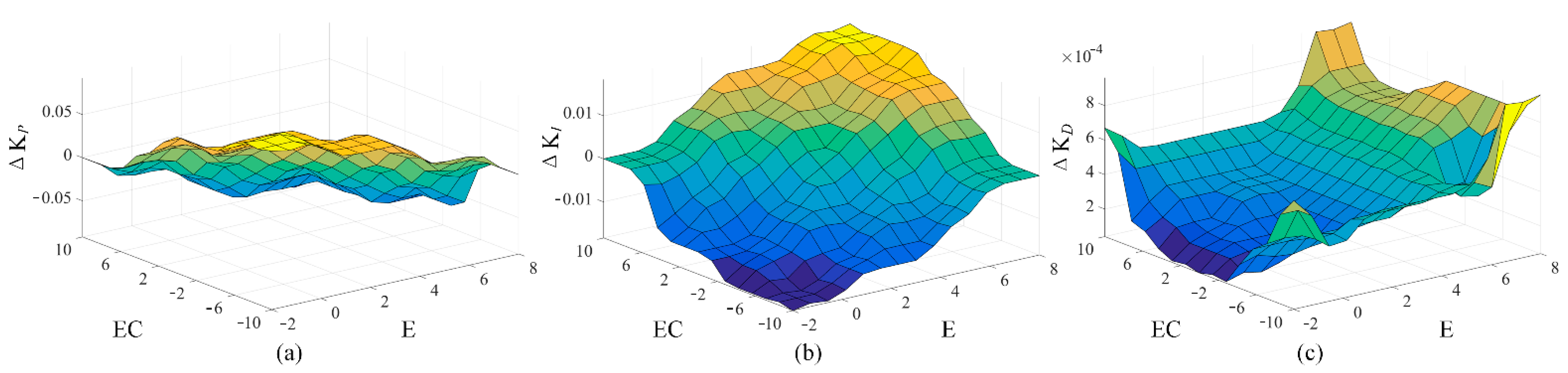
4.2.2. Fuzzy Adaptive PID Controller
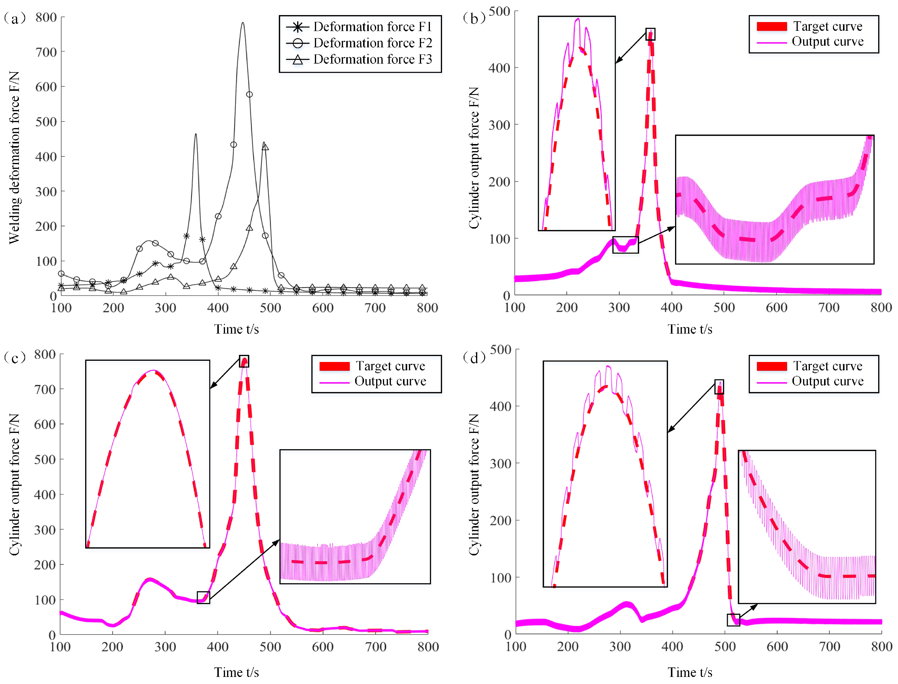
The clamping force servo control system controls output force of the driving cylinder of the hook-pull device by adopting fuzzy adaptive PID control algorithm. The control algorithm model was established in MATLAB/Simulink, as shown in Figure 10.
E is the deviation between the setting clamping force value and the feedback value, EC is the rate of change E. They are the input variables of the system. Universe of the deviation E and its change rate EC is [−2, 8], [−10, 10], respectively, and their corresponding fuzzy subset is [Nb, NM, NS, ZO, PS, PM, PB]. Output of the controller is the increment of three parameters of PID control algorithm (i.e., increment of proportional coefficient ΔKP, increment of integral coefficient ΔKI, and differential coefficient increment ΔKD). The basic universe of scale factor increment ΔKP, ΔKI, and ΔKD is [−0.1, 0.1], [−0.02, 0.02] and [0, 0.001] respectively. Their fuzzy subset is [NB, NM, NS, ZO, PS, PM, PB].
The triangular membership function was adopted to deal with the fuzzy subset transformed from input variables and output ones. The fuzzy rule table is established by Mamdani’s [14] reasoning method. In order to obtain the accurate incremental value of PID parameters, the centroid method [15] was selected as the defuzzification method after fuzzy reasoning. The fuzzy output under different deviation E and deviation change rate EC is shown in Figure 11.

4.3. Co-Simulation

In this paper, a co-simulation model of the pneumatic circuit model and fuzzy adaptive PID control algorithm model of control system was established using the interface between AMESim and MATLAB, and then the whole system was simulated and analyzed. The output signal of AMESim model is clamping force single, and the input signal of AMESim model is the electrical proportional valve control voltage signal. The co-simulation model consists of the MATLAB and AMESim models through data interfaces.
Based on the co-simulation model, the clamping force dynamic servo control system was simulated, and the welding deformation force was taken as the target curve signal. The cylinder output forces at three constraint positions obtained through the joint simulation are shown in Figure 12. The simulation results show that the control algorithm adopted in this paper can realize dynamic adjustment function of the output signal following the target curve and owns fast response speed and good following performance. Therefore, the established servo control system can dynamically adjust the output force of the cylinder by following the MIG welding deformation force.

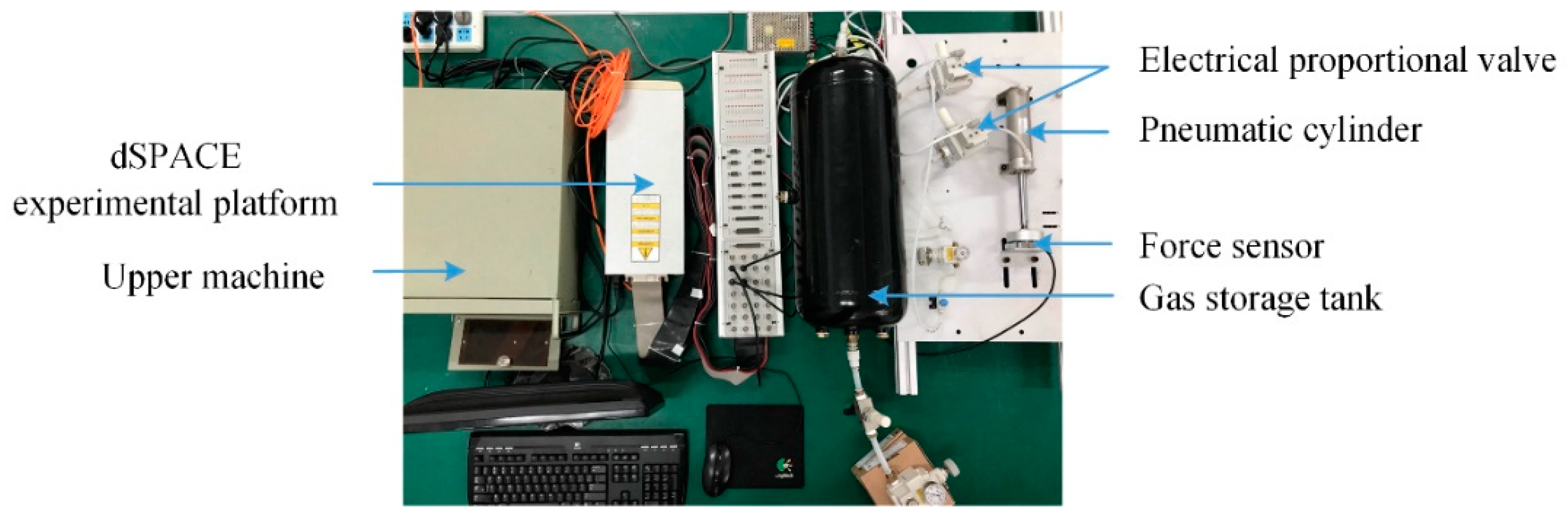
5. Experimental Verification

5.1. Experimental Verification of Dynamic Adjustment of Clamping Force

The off-line simulation verified the correctness of the control algorithm in the clamping force servo control system. Considering the gap between off-line simulation and actual system, further experimental verification was needed. Therefore, an experimental platform for clamping force servo control system was built based on dSPACE, as shown in Figure 13.
Then, dynamic adjustment function of clamping force in the clamping scheme was verified by using the experimental platform. In the experiment, the target curve is MIG welding deformation force curve, and the dynamic experimental adjustment results of clamping force are shown in Figure 14.
Under the action of the clamping force servo control system, there is a tiny time delay in the actual output force of the cylinder, resulting in fluctuation of output force. The maximum fluctuation errors for F1, F2, and F3 target curves are 5.97 N, 5.59 N, and 6.96 N respectively. They are within the allowable range of error, which is defined as no more than 7 N. Therefore, the clamping force servo control system established in this paper can make the driving cylinder adjust the output force with the change of the target curve.

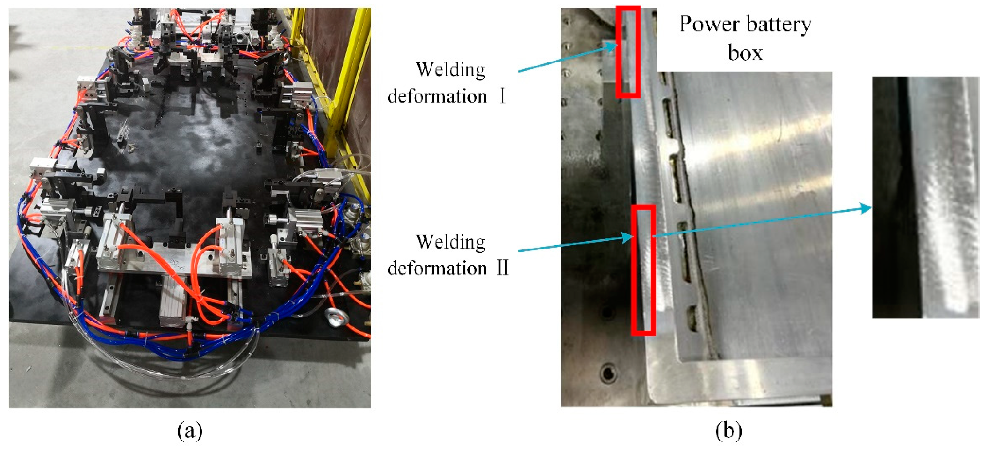
5.2. Experimental Verification of MIG Welding Deformation Inhibition of Power Battery Enclosure

In order to verify the correctness of the MIG welding clamping scheme of the power battery enclosure proposed in this paper, the MIG welding clamp for the bottom plate and frame of the power battery enclosure was manufactured as shown in Figure 15a. The welding experiment was carried out on the clamp, and the experimental welding deformation results are shown in Figure 15b. It can be found that there are two areas with large residual deformation after welding. After measurement, the residual deformation I after welding shrinks inward by 0.3 mm, and the residual deformation II after welding shrinks inward by 0.6 mm, both of which are less than 1.2 mm specified in the requirements. Thus, the correctness of this scheme was verified.

6. Summary

Aiming at restraining welding deformation, this paper proposed and verified the MIG welding clamping scheme of power battery enclosure by combining simulation and experiment. Based on the MIG welding process of power battery enclosure, a MIG welding simulation model was established. By adopting the finite element theory of welding thermal process, the clamping force curve required to restrain welding deformation was calculated. In order to accurately control the clamping force of the clamp, a dynamic servo control system and control algorithm of the clamping force was designed. Correctness of the control system was verified by simulation analysis with MATLAB and AMESim. Then, an experimental platform based on dSPACE was built to verify the dynamic adjustment function of clamping force in the clamping scheme. Finally, correctness of the scheme proposed in this paper was verified by field experiments. The research work has provided a good reference for solving welding problems of other kinds of power battery enclosures.

Author Contributions

Conceptualization, J.X.; data curation, J.Z.; methodology, J.X.; project administration, G.L.; writing—review and editing, J.X. and G.L. All authors have read and agreed to the published version of the manuscript.

Funding

This research received no external funding.

Conflicts of Interest

The authors declare no conflict of interest.

References

  1. Ueda, Y.; Yamakawa, T. Analysis of thermal elastic-plastic stress and strain during welding by finite element method. Jpn. Weld. Soc. Trans. 1971, 2, 90–100. [Google Scholar]
  2. Okumoto, Y.; Yanai, H.; Tsuda, Y.; Kanazawa, I.; Kutsuwa, K.; Kasuya, T.; Engineers, O. Study on Plate Deformation due to Fillet Welding at Sub-assembly Stage. J. Jpn. Soc. Nav. Archit. Ocean. Eng. 1995, 1995, 339–346. [Google Scholar] [CrossRef]
  3. Bachorski, A.; Painter, M.J.; Smailes, A.J.; Wahab, M.A. Finite-element prediction of distortion during gas metal arc welding using the shrinkage volume approach. J. Mater. Process. Technol. 1999, 92–93, 405–409. [Google Scholar] [CrossRef]
  4. Spina, R.; Tricarico, L.; Basile, G.; Sibillano, T. Thermo-mechanical modeling of laser welding of AA5083 sheets. Journal of Materials Processing. Technol. Procedia Eng. 2007, 191, 215–219. [Google Scholar]
  5. Piekarska, W.; Rek, K. Numerical Analysis and Experimental Research on Deformation of Flat Made of TIG Welded 0H18N9 Steel. Procedia Eng. 2017, 177, 182–187. [Google Scholar] [CrossRef]
  6. Cai, Z.P.; Zhao, H.Y.; Lu, A.L.; Cai, Z.Y. Derivation and Verification of Similarity Criteria for Welding Temperature Field, Stress Field and Strain Field. Chin. Mech. Eng. 2001, 10, 85–88. [Google Scholar]
  7. Li, X.D.; Li, G.C.; Zhu, Z.M.; Xu, F.L. Engineering Application of Simulation and Prediction of Welding Deformation in MIG Welding of Aluminum Alloy Sheet. Trans. China Weld. Inst. 2014, 35, 104–108,118. [Google Scholar]
  8. Cai, J.P.; Jiang, X.H.; Zhang, Y.J.; Deng, D.A. Effect of Groove Type on Residual Stress and Deformation of SUS304 Austenitic Stainless Steel Butt Joint. Trans. China Weld. Inst. 2016, 37, 63–66,132. [Google Scholar]
  9. Chen, Z.; Li, C.; Han, X. Sensitivity analysis of the MIG welding process parameters based on response surface method. J. Adhes. Sci. Technol. 2020, 10, 1–20. [Google Scholar] [CrossRef]
  10. Samad, Z.; Nor, N.M.; Fauzi, E.R.I. Thermo-Mechanical Simulation of Temperature Distribution and Prediction of Heat-Affected Zone Size in MIG Welding Process on Aluminium Alloy EN AW 6082-T6. Mater. Sci. Eng. 2019, 530, 012016. [Google Scholar] [CrossRef]
  11. Lei, W.; Mitsuyosi, T. Comparison of Residual Stress Between MIG Welding and Friction Stir Welding. Appl. Mech. Mater. 2012, 1682, 155–156. [Google Scholar]
  12. Prisco, U. Shape of the melt pool produced by a moving Gaussian heat source. Weld. Woeld 2021, 65, 2105–2118. [Google Scholar] [CrossRef]
  13. Fu, L.; Du, S.G. Progress in Numerical Simulation of Friction Welding Process. Trans. China Weld. Inst. 2001, 5, 87–92,80. [Google Scholar]
  14. Shimakawa, M. A Study on Particle Fuzzy Reasoning Method. In Proceedings of the Innovative Computing, Information and Control, Kumamoto, Japan, 5–7 September 2007. [Google Scholar]
  15. Huang, Z.; Qiang, S. A new fuzzy interpolative reasoning method based on center of gravity. In Proceedings of the 12th IEEE International Conference on Fuzzy System, St. Louis, MO, USA, 25–28 May 2003. [Google Scholar]
Figure 1. Structure of the power battery enclosure.
Applsci 12 06598 g001
Figure 2. Clamping modules.
Applsci 12 06598 g002
Figure 3. Thermophysical property parameters of 6005A aluminum alloy material: (a) the density of 6005A aluminum alloy change curve with temperature; (b) the heat capacity of 6005A aluminum alloy change curve with temperature; (c) the thermal conductivity of 6005A aluminum alloy change curve with temperature.
Applsci 12 06598 g003
Figure 4. Gaussian heat source model.
Applsci 12 06598 g004
Figure 5. Thermal cycle curve of short-side weld and long-side weld of power battery enclosure: (a) the short side weld and the welding temperature curves of simulation and experiment; (b) the long side weld and the welding temperature curves of simulation and experiment.
Applsci 12 06598 g005
Figure 6. Constraints of the power battery enclosure.
Applsci 12 06598 g006
Figure 7. Variation curve of welding deformation reaction force of left crossbeam: F1 is the welding deformation force of the forward measurement points in the left crossbeam; F2 is the welding deformation force of the middle measurement points in the left crossbeam; F3 is the welding deformation force of the rear measurement points in the left crossbeam.
Applsci 12 06598 g007
Figure 8. Schematic diagram of clamp’s pneumatic servo control system.
Applsci 12 06598 g008
Figure 9. AMESim simulation model of clamp’s pneumatic servo control system.
Applsci 12 06598 g009
Figure 10. Simulation model of fuzzy PID controller.
Applsci 12 06598 g010
Figure 11. Defuzzification surfaces under different inputs: (a) the defuzzification surfaces of ΔKP under different inputs; (b) the defuzzification surfaces of ΔKI under different inputs; (c) the defuzzification surfaces of ΔKD under different inputs.
Applsci 12 06598 g011
Figure 12. Co-simulation results.
Applsci 12 06598 g012
Figure 13. Experimental platform of pneumatic servo control system.
Applsci 12 06598 g013
Figure 14. Experimental results:(a) the target curves of three limited locations; (b) the output curve when the input target curve is F1; (c) the output curve when the input target curve is F2; (d) the output curve when the input target curve is F3.
Applsci 12 06598 g014
Figure 15. Welding fixture and deformation diagram after welding: (a) the welding clamp; (b) welding experiment results.
Applsci 12 06598 g015
Table 1. Welding simulation parameters.
NameParameter
Welding voltage18 V
Welding current170 A
Thermal efficiency0.72
Welding speed10 mm/s
Blackbody radiation constant5.67 × 10−8 W/(m2·K4)
Table 2. Simulation parameters of ITV3050 electro-proportional valve.
NameParameter
Effective area at the top of the valve stem4.13 × 10−4 m2
Effective area at the bottom of the valve stem3.27 × 10−4 m2
Component quality of valve stem8 × 10−2 kg
Equivalent spring stiffness2.2 × 105 N/m
Value of intake spool spring pre-compression2.4 × 10−4 m
Value of outtake spool spring pre-compression1.6 × 10−4 m
Publisher’s Note: MDPI stays neutral with regard to jurisdictional claims in published maps and institutional affiliations.

