Article

Research on Adhesive Coefficient of Rubber Wheel Crawler on Wet Tilted Photovoltaic Panel

1
National Key Laboratory of Digital Control and System Engineering (DCSELab), Ho Chi Minh City University of Technology (HCMUT), 268 Ly Thuong Kiet Street, District 10, Ho Chi Minh City 700000, Vietnam
2
Faculty of Mechanical Engineering, Ho Chi Minh City University of Technology (HCMUT), 268 Ly Thuong Kiet, District 10, Ho Chi Minh City 700000, Vietnam
3
Vietnam National University Ho Chi Minh City, Linh Trung Ward, Thu Duc District, Ho Chi Minh City 700000, Vietnam
4
Faculty of Electronics and Telecommunication, Saigon University, Ho Chi Minh City 700000, Vietnam
*
Author to whom correspondence should be addressed.
Appl. Sci. 2022, 12(13), 6605; https://doi.org/10.3390/app12136605
Submission received: 2 June 2022 / Revised: 27 June 2022 / Accepted: 27 June 2022 / Published: 29 June 2022

Abstract

:
The demand for renewable energy sources is growing fast because of the negative impact of the utilization of fossil energy, nuclear energy, and hydroelectricity. One of the renewable energy sources, known as solar energy, which uses the photovoltaic panel (PV) to generate electricity from the sun, is a promising alternative that has great potential to deal with the power crisis. However, the power productivity and efficiency conversion are affected significantly by dust accumulation on PVs. Many researchers investigated PV panel dust cleaning methods to improve performance, yield, and profitability. Various dust cleaning and mitigation methods such as rainfall, labor-based, and mechanized cleaning are explored, and we demonstrated that dust removal could be automated with cleaning robots effectively. Due to the specified geographical site of PV panel installation, cleaning robots might work on the misalignment and uneven PV arrays, presenting huge challenges for an autonomous cleaning robot. Thus, a rubber wheel crawler robot with semi-autonomous handling provides a flexible motion that is a well-suited solution to clean rooftop PV arrays. Nevertheless, the rubber wheel crawler robot might suffer slippage on the wet glass of tilted PV arrays. This paper studies the anti-slip effect of the rubber wheel crawler equipped with a cleaning robot under the wet surface of tilted PV panels. First, a theoretical model consisting of several parameters is established to validate the slippage of the rubber wheel crawler on the wet tilted PV. Then, some parameters of the theoretical model are approximated through experimental tests. Finally, simulation results of the theoretical model are conducted to evaluate the accuracy of the proposed theoretical model in comparison to the experimental results under the same working conditions. The merits provide the efficient design of rubber wheel crawlers, enabling the anti-slip ability of robots.

1. Introduction

The vogue of smart home technology [1] alongside intelligent compliances and the development of industry 4.0 [2] gaining production capabilities [3] due to computerization manufacturing, cloud computing, and robotic systems [4,5] have increased the demand of energy resources. However, the fossil energy sources are quickly exhausted [6] and cause environmental pollution [7]. Meanwhile, nuclear energy might harm not only humans but also animals and plants, as it causes mutations in DNA [8,9], and the habitat takes a long time to recover [10]. This energy crisis has led to the introduction of renewable energy as a potential alternative [11]. Recently, solar energy, which generates electricity using the photovoltaic (PV) panel, has increased exponentially in many developed and developing tropical countries around the world [12,13]. The growth of solar energy is indicated by the increasing installed capacities in both rooftop PV panel arrays for small-scale applications and concentrated PV panel arrays for mainstream power [14,15,16]. Among all the other renewable energy sources, solar energy systems have many advantages in terms of flexible installation sites, cheap maintenance and installation costs, and being environmentally friendly. However, the efficient conversion of the solar energy system is decreased significantly by two merits parameters: cloudy days and accumulated dust [17]. Additionally, the longevity of PV panels is affected by heating induced on dirty PV cells.
Some researchers have studied the degradation of PV panels output [18,19,20] under the accumulated dust. In Europe and the Middle East, the efficiency of dirty PV panels decreases by 3–6% per year, while it has decreased by more than 30% in India and the Arabian Peninsula [21,22,23]. For tropical countries such as Thailand and Vietnam, this is problematic, with the efficiency of solar cells decreased by 35% [24]. The work [25] has pointed out that a clean PV panel can improve performance considerably and yield more than the dirty one. Some of the cleaning methods for PV panels, such as rainfall cleaning [26,27,28], labor-based cleaning [29], and mechanized cleaning [30,31], were introduced in the past. The rainfall cleaning method requires a large tilted angle of PV panels that are not costly to clean and mitigate loose dust on the PV surface. However, the disadvantage of this method is that it depends on the rainfall intensity at the installation site. If the rainfall is insufficient, it will cause sludge formation on the PV panel, or only large particles will be removed [32]. Thus, the rainfall cleaning method has low efficiency and is mainly adopted in areas where it is hard to reach for maintenance [33,34]. The labor-based cleaning method requires costly time, human resources, water, and cleansing facilities [35]. This cleaning method can improve the conversion efficiency and cool down the PV panel [36,37,38,39,40], but it is an expensive cleaning cost compared to the rainfall cleaning method [41]. Furthermore, cleansing facilities might scratch the dry PV panel surfaces [35]. As well, human workers cannot maintain their focus on work due to declining physical conditions under the prolonged cleaning time. Mechanized cleaning methods employ motorized cleaning brushes or portable cleaning robots [42,43,44,45,46] and water supply to clean the PV panel surface [47]. The study [48] pointed out that this cleaning method should be applied to clean the PV panels once per week or daily when the rate of dust is intense. The benefit of the mechanized cleaning method is to cool PV panels with water, use automated operation by cleaning robots, and save human resources [49]. Alternatively, the PV cleaning robot can be classified into two categories. The first is to use two motorized trolley carriers clamping on the top and bottom edge of the PV panel [15] to move throughout the PV panel arrays, which is well-suited for mainstream power with massive concentrated PV panel arrays. The other is based on the structure of rubber wheel crawler robots, which is preferred for small-scale PV systems [29]. The advantages of this type of robot are portability and the ability to work with misalignment and uneven surfaces of PV panels. The drawback is that it requires human teleoperation, and the cleaning robot might slip on a wet tilted PV panel.
In Vietnam, the rooftop PV system has grown exponentially, with the capacity installations adding 9.3 gigawatts (GW) to its national grid at the end of 2020 compared to that of 378 megawatts (MW) in 2019. This leads to the increasing demand for cleaning accumulated dust on the rooftop PV panels. As aforementioned, a rubber wheel crawler robot with the anti-slip ability on the wet large tilted angle of PV panels seems to be the well-suited solution. This paper studies the anti-slip effect of a rubber wheel crawler equipped with cleaning robots on the wet large tilted angle of the rooftop PV panel. The objective of this study is to establish the relationship between the friction coefficient of the rubber wheel crawler and the surface of the PV panel with respect to various conditions such as the tilted angle of the PV panel, rubber hardness, and dry/wet surfaces.

2. Materials and Methods

The cleaning robot which is used to clean the accumulated dust on the glass surface of the PV panel arrays consists of three modules: two rotating brushes with a water supply and a chassis module equipped with two rubber wheel crawlers that contains an electrical enclosure and battery. The rubber wheel crawler is driven by two primary timing pulleys through a timing belt coated with rubber trackpads. The PU timing belt is supported by auxiliary free wheels that can hump when moving on the misalignment/uneven surface, thanks to the spring tensioners. The rubber wheel crawlers provide the cleaning robot the ability to move on the PV panel surfaces longitudinal to its chassis as well as rotate in place. The usage of the rubber wheel crawler enables a larger area of contact between the cleaning robot and the PV panel surface than the usage of traditional wheels, leading to increased friction force. For the slightly tilted angle of the PV panel (less than 10 ° ), there is no/rarely slip on the rubber wheel crawler and the PV panel surface; the cleaning robot moves along/orthogonal to the slope of PV panels. However, when there are PV panels with a large tilted angle (over 10 ° ) in wet conditions, this is a major challenge for researchers to increase the slip resistance between the rubber track and PV panel surface. According to [27,50,51,52,53,54], the tilted angle of the PV panel varies 0 ° ÷ 60 ° due to the geographical installation site. The larger tilted angle of PV panels leads to the lower slip resistance at the rubber wheel crawler and PV panels. There are many factors that affect the slip resistance between the rubber wheel crawler and PV panel surfaces: for instance, spring forces, the area of contact, and the weight of the cleaning robot. However, this paper mainly investigates the characteristics of the rubber materials coated on the trackpad of the timing belt to improve the slip resistance by optimizing the reaction force.
Assumption:
  • There is no slip on the primary timing pulleys and the PU timing belt;
  • The tensions of the PU timing belts on both sides of the cleaning robot are the same;
  • The slip resistance is not affected by the direction of rotation of the broom
Consider the cleaning robot in the stationary state on the PV panel with a tilted angle α ( 0 ° α 60 ° ), as shown in Figure 1. The cleaning robot is applied by the cleaning robot’s gravity ( P ), the reaction force ( N ), the static friction force between the belt and the panel surface ( F f r ) [55,56,57,58,59,60], and the elastic force of the timing belts ( F E ). According to the no-slip condition, the greater the static friction, the larger the slip resistance. On the other hand, the static friction force must be larger than the cleaning robot’s gravity to ensure the no-slip condition of the cleaning robot.
F f r P
With the tilted angle α of the PV panel, the amplitude of the cleaning robot’s gravity projected into the shopfloor is calculated by the term of P sin α . The amplitude of the static friction force is a product of the coefficient of friction ( μ ) and reaction force (N) [61,62]. Equation (1) described the adhesive condition between the rubber track and PV panel surface.
μ N P sin α 0
It can be seen from Equation (2) that the adhesive condition depends on the reaction force (N). The larger the reaction force, the higher the slip resistance. It is evident that the reaction force increases as the cleaning robot’s weight increases; however, this is impossible because the weight of the cleaning robot should be minimized to avoid the overload of the PV panel.
Figure 2 describes the equivalent model of the rubber trackpad coating belt. The elastic characteristic of the rubber trackpad is denoted by springs in parallel with the spring stiffness (K) and the displacement ( Δ L ) that produce the elastic force ( F E ) in the opposite of the direction of the cleaning robot’s gravity. Applying Newton’s third law, the relationship between the reaction force, the cleaning robot’s gravity, and the elastic force can be expressed as follows:
N = P F E
where the elastic force ( F E ) is a product of the spring stiffness (K) and the displacement ( Δ L ) according to Hooke’s law that can be calculated as
F E = K Δ L
By using the projection of Equation (3) into the perpendicularity of the ground, Equations (2) and (4) can be rewritten as follows:
( ( P cos α K Δ L ) μ P sin α ) 0
Equation (5) implies that the spring stiffness (K) and the displacement ( Δ L ) of the equivalent model and the static friction coefficient ( μ ) should be known to determine the adhesive bonding of the cleaning robot and PV surfaces. These parameters strongly depend on the hardness of the rubber material coating on the rubber track belt. Similar to the material used for the tires, it is made of rubber with variable hardness, according to [63]. From the perspective of anti-slip, the key feature of each type of material is the coefficient of friction between its contact surface and the PV panel surface. According to the experimental research [64], the static friction coefficient ( μ ) is a function of shore hardness. The function μ is simplified in the linear form as follows:
μ x S + y
where x is the slope of the function u; and y is the maximum coefficient of friction that is determined by practical experiments through the utilization of zero shore harness material.
The spring stiffness (K) and the displacement ( Δ L ) of the equivalent model of a rubber track belt can be determined based on the principle of a measurement device called a durometer, which is used to measure the hardness of materials. The durometer consists of an indentor with the standard weight and a calibrated spring, as shown in Figure 3a. The equivalent model of the durometer can be described in Figure 3b. The material with a thickness ( L 0 ) and shore hardness (S) can be represented by a spring with the stiffness ( K S B ) and the displacement ( Δ L S B ).
Applying a Free Body Diagram to the equivalent model of a durometer, the sum of gravity of the indentor ( P I ), the shore above force of the calibrated spring ( F S A ) and the shore below force of the equivalent spring ( F S B ) can be calculated by:
F S A + P I + F S B = 0
It can be seen from Figure 3b that the shore below force of the equivalent spring ( F S B ) is opposite to the other two forces, thus:
F S A + P I = F S B
The gravity of the indentor with the standard mass (m) of 0.822 kg is calculated as P I = m g , where g is the gravity acceleration of 9.81 m/s2.
The shore above force ( F S A ) can be simplified as a linear function depending on the shore hardness (S) [63]:
F S A = 0.550 + 0.075 S
The shore below force of the equivalent spring is a product of the spring stiffness ( K S B ) and the displacement ( Δ L S B ):
F S B = K S B Δ L S B
According to [63], the displacement ( Δ L S B ) is inversely proportional to the shore hardness expressed in millimeters:
Δ L S B = 0.0254 100 S 100
Substituting Equation (10) into Equation (8) yields:
K S B = F S A + P I Δ L S B
Equations (7)–(12) are only used to determine the equivalent spring stiffness in the case of the small cross-section of the indentor top interacting with the effective area (a). For the case of the rubber trackpad in contact with the PV surface, the effective area (A) is much more than (a). The effective area (A) is the product of maximum length ( l m a x ) and width ( w m a x ) of the rubber wheel crawler (Figure 4).
A = l m a x w m a x
The equivalent spring stiffness of the rubber track belt is calculated by integrating the small stiffness values ( K S B ) for each effective area (a) as below:
K = 0 l m a x 0 w m a x K S B A w l d w d l
It can be seen from Equation (14) that the equivalent spring stiffness (K) depends on the efffective area (A) and the maximum length ( l m a x ), which are strongly affected by the shore hardness.
Similarly to the characteristic of the equivalent spring stiffness (K), the displacement ( Δ L ) of the rubber track belt depends on the shore hardness, the effective area, the applied force, the initial thickness of the material layer, and Young’s stress module (E).
According to the references [65,66], the correlation between Young’s stress module (E) and the shore hardness is expressed by:
E = 0.0981 ( 56 + 7.62336 S ) 0.137505 ( 254 2.54 S )
On the other hand, Young’s stress module can be derived by Hooke’s law [67]:
E = F L 0 A Δ L
where F is the gravity force reacting on the effective area A, and L 0 is the initial thickness of the specimen.
Substituting Equation (15) into Equation (16) yields
E = F L 0 A 0.137505 ( 254 2.54 S ) 0.0981 ( 56 + 7.62336 S )
Equation (17) shows that there is a correlation between the effective area (A) and the displacement ( Δ L ). The effective area A is formed by the gravity force of the cleaning robot reacting to the contact area between the timing pulley and the rubber track belt (Figure 5).
A = l m a x w m a x = 2 w m a x R 2 ( R Δ L ) 2
where R is the radius of the timing pulley.
By substituting Equation (18) into Equation (16), it can be deduced that
Δ L = F L 0 2 E w m a x 2 R Δ L Δ L 2

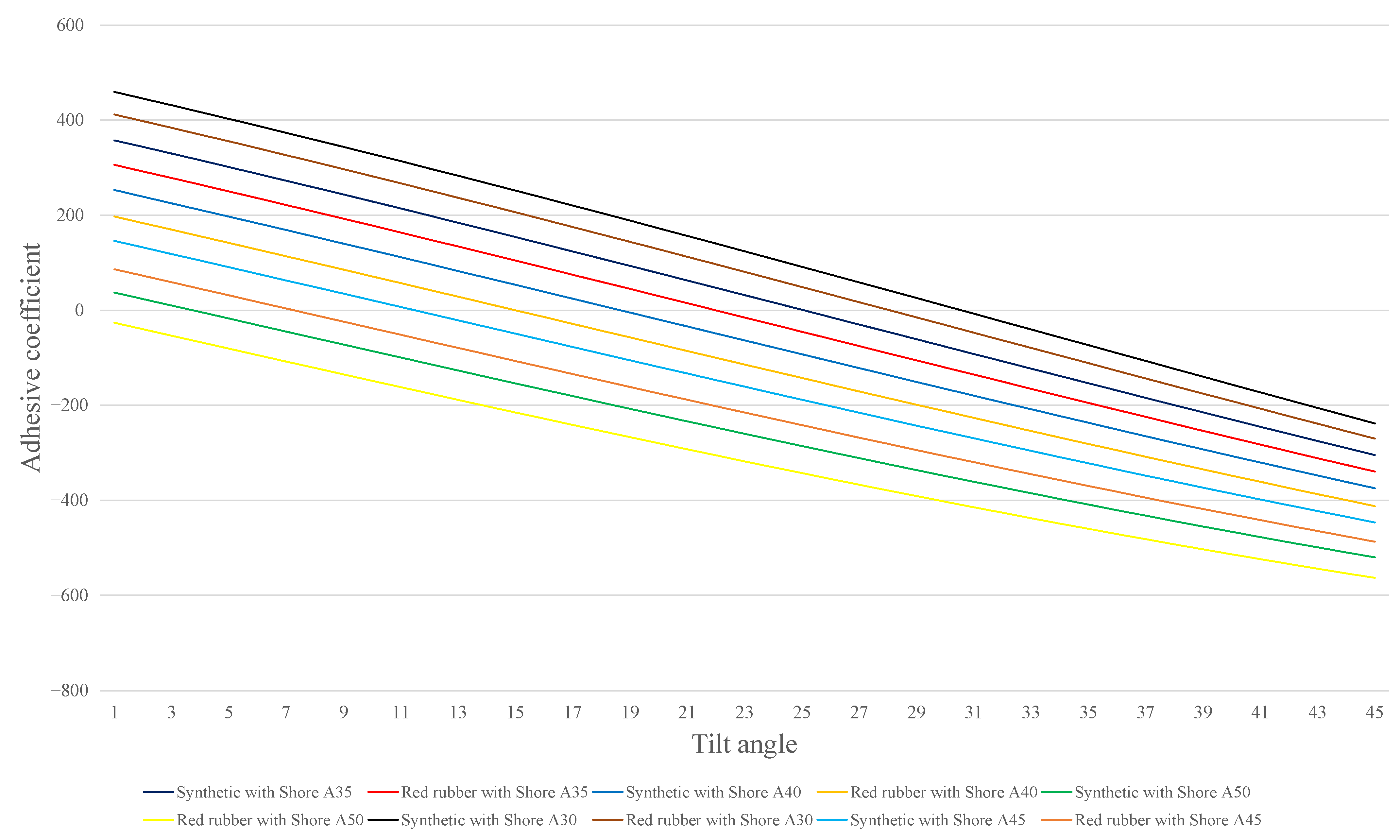
3. Experimental Study

The logic of this study has the sequence of first including the introduction of the theoretical model. Then, some parameters of this model are obtained through experiment and computational theory. Finally, the relationship between the shore hardness, adhesive coefficient, and the maximum tilted angle of PV is established by simulation studies.
A prototype of a rubber wheel crawler is made and equipped with a PV cleaning robot, as shown in Figure 6. The rubber wheel crawler comprises a seamless polyurethane (PU) timing belt with a T10 tooth profile, which runs over two-timing pulleys. The PU timing belt is 75 mm wide, of length 1690 mm, and it has a rubber coating with a cuboidal back-profile to gain the adhesive coefficient of the robot on the slippage surface of PV. The physical parameter of the rubber wheel crawler is designed as shown in Table 1. The PV cleaning robot, which is 80 kg in weight, is designed to move on the tilted angle PV of 0 ° ÷ 45 ° .
To compare the adhesive coefficient of the coating material, there are two types of rubber materials that are utilized to coat the PU timing belt, which are known as red rubber and synthetic rubber. Both types of rubber wheel crawlers are equipped with the PV cleaning robot for working on the same testing conditions. The shore hardness of both types of rubber is verified by a durometer. The tilted angle of the PV panel can vary 0 ° ÷ 45 ° , which is measured by an inclinometer, while it is moistened by the stable water flow supply. The PV cleaning robot is required to move on the PV panel transversely with a travel length of 5 m for every 5 ° increasing the tilted angle PV. The slippage state of the PV cleaning robot on the PV surface is defined as the robot being shifted longitudinally to the PV panel by at least 10 cm, which is measurable by using a laser alignment tool.
By conducting experiments on the synthetic rubber track belt with the shore hardness of A35 and the maximum tilted angle of 25 ° , the coefficient of friction for the case of using a synthetic coating is determined through Equation (5) as follows:
μ s y n P sin α P cos α K Δ L = 0.5275
By recalling Equation (6) and assimilating with Equation (20), the range of x, y of Equation (6) is determined by referring to the reference [64]:
{ 1.1431 < y < 2.0494 0.0435 < x < 0.0176
The values of x, y are approximated as follows:
μ s y n 0.0305 S + 1.5963
In the same manner, the coefficient of friction for the case of using a red rubber coating with the shore hardness of A40 and the maximum tilted angle of 15 ° is determined by
μ s y n 0.0315 S + 1.5578
For each tilted angle increment and different materials, there exists a certain shore hardness in such a way that can seek the optimal adhesion. Similarly, for each certain shore hardness, there exists a maximum tilted angle value that the cleaning robot can move without slippage.
By using Equations (5), (14), (19) and (22) and referring to Table 1, it can be easy to verify the robot slippage through the below equation:
( P cos α ( 0 l m a x 0 w m a x K L B A l w d w d l ) Δ L ) ( x S + y ) P sin α 0
The cleaning robot can move on the PV surfaces without slippage if Equation (24) is satisfied; otherwise, it might be slipped.
For a given shore hardness, there exists a maximum tilted angle in such a way that Equation (24) is satisfied. Once the shore hardness is increased, the tilted angle of the PV that the cleaning robot can move without slippage decreases. Figure 7 illustrates the adhesive coefficient with respect to the tilted angle of the PV that enables the cleaning robot to move without slippage, corresponding to synthetic/red rubber of varying shore hardness in a range of A30–A50. The maximum tilted angle that the cleaning robot can move without slippage with respect to the coating materials is briefly described in Table 2.
Figure 8 shows the characteristic of shore hardness and the adhesive coefficient for synthetic/red rubber in the case of the tilted angle increment 5 ° from 15 ° ÷ 30 ° . The maximum shore hardness that enables the cleaning robot to move without slippage corresponding to each increment step of the tilted angle is briefly described in Table 3.
It can be seen from Figure 8 and Table 3 that the harder the shore hardness, the lower the adhesive coefficient. It can be realized that the shore hardness reaches over A42 for the synthetic rubber, leading to the robot slippage in the 15 ° tilted angle case, and the best adhesive of the robot when the belt hardness is Shore A7 for both rubbers. However, the rubber track belt made of rubber with low shore hardness is easily destroyed by high pressure. Additionally, it is noted that the shore hardness is proportional to the adhesive coefficient in the transient stage for the shore hardness less than A7. This can be explained by the destruction of the bond structure of rubber material that has reached the compression limit.

4. Conclusions

This paper investigated the adhesive coefficient of the rubber wheel crawler with the coating material of synthetic and red rubber on the wet tilted PV by introducing the theoretical model to validate the slippage. The theoretical model was established by using the physical laws and deriving parameters from experiments. The accuracy of the proposed theoretical model was evaluated through the comparison between simulation and experimental results. Through the theoretical model, it can be pointed out that the shore hardness of A7 can provide the biggest adhesive coefficient; however, it is hard to manufacture the rubber track belt with a durable lifetime. The shore hardness over A40 can cause the slippage of the rubber wheel crawler. For a specified application, the anti-slippage of the rubber wheel crawler can be verified by the proposed theoretical model. For a different tilted angle of the shopfloor, robot weight, and track belt material, one can seek the optimal value for a certain case. In this paper, some assumptions are given to simplify the consideration of the adhesive coefficient. The limitation of this paper is that the adhesive coefficient is considered under some given assumptions. First, the contact area between the rubber wheel crawler and the PV surfaces is uniform at all points. Then, the drive efficiency of the rubber track belt and the timing pulley is ignored. Next, the belt tension and the contact area of the rubber wheel crawler and the PV surfaces are the same as the two sides of the cleaning robot. Finally, the affection of the rotating brush to the robot slippage is ignored.
This paper mainly focuses on the shore hardness of the coating material on the rubber wheel crawler affecting the adhesive coefficient when the cleaning robot moves on the wet PV surface. For future research, the structure of coating the trackpad with a deep-recessed pattern is an interesting topic.

Author Contributions

Data curation, M.T.N. and V.T.N.; Formal analysis, C.T.T.; Project administration, H.H.N.; Supervision, T.T.N.; Writing—original draft, M.T.N. and C.T.T.; Writing—review editing, V.T.D. and T.T.N. All authors have read and agreed to the published version of the manuscript.

Funding

This research is funded by Vietnam National University Ho Chi Minh City (VNU-HCM) under grant number C2021-20-10.

Institutional Review Board Statement

Not applicable.

Informed Consent Statement

Not applicable.

Data Availability Statement

Data sharing is not applicable to this article.

Acknowledgments

This research is funded by Vietnam National University Ho Chi Minh City (VNU-HCM) under grant number C2021-20-10. We acknowledge the support of time and facilities from the Nation Key Laboratory of Digital Control and System Engineering (DCSELab), Ho Chi Minh City University of Technology (HCMUT), VNU-HCM for this study.

Conflicts of Interest

The authors declare no conflict of interest.

References

  1. Nacer, A.; Marhic, B.; Delahoche, L. Smart Home, Smart HEMS, Smart heating: An overview of the latest products and trends. In Proceedings of the 2017 6th International Conference on Systems and Control (ICSC), Batna, Algeria, 7–9 May 2017; pp. 90–95. [Google Scholar]
  2. Contreras, J.D.; Garcia, J.I.; Pastrana, J.D.D. Developing of industry 4.0 applications. Int. J. Online Eng. 2017, 13, 30–47. [Google Scholar] [CrossRef]
  3. Thoben, K.D.; Wiesner, S.A.; Wuest, T. ‘Industrie 4.0’ and smart manufacturing-a review of research issues and application examples. Int. J. Autom. Technol. 2017, 11, 4–16. [Google Scholar] [CrossRef] [Green Version]
  4. Kumar, A. Methods and Materials for Smart Manufacturing: Additive Manufacturing, Internet of Things, Flexible Sensors and Soft Robotics. Manuf. Lett. 2018, 15, 122–125. [Google Scholar] [CrossRef]
  5. Dilberoglu, U.M.; Gharehpapagh, B.; Yaman, U.; Dolen, M. The Role of Additive Manufacturing in the Era of Industry 4.0. Procedia Manuf. 2017, 11, 545–554. [Google Scholar] [CrossRef]
  6. Withagen, C. Pollution and exhaustibility of fossil fuels. Resour. Energy Econ. 1994, 16, 235–242. [Google Scholar] [CrossRef]
  7. Balat, A.M.; Ayar, G.; Oguzhan, C.; Uluduz, H.; Faiz, U. Influence of fossil energy applications on environmental pollution. Energy Sources Part Econ. Plan. Policy 2007, 2, 213–226. [Google Scholar] [CrossRef]
  8. Claußen, A.; Rosen, A. 30 Years Living with Chernobyl 5 Years Living with Fukushima Health Effects of the Nuclear Disasters in Chernobyl and Fukushima; IPPNW: Berlin, Germany; Physicians for Social Responsibility (PSR): Washington, DC, USA; PSR/IPPNW: Lucerne, Switzerland; IPPNW Austria (OMEGA): Wien, Austria, 2016. [Google Scholar]
  9. Loganovsky, K. DO low doses of ionizing radiation affect the human brain? Data Sci. J. 2009, 8, 13–35. [Google Scholar] [CrossRef]
  10. Bourguignon, D.; Scholz, N. Chernobyl 30 Years on: Environmental and Health Effects; European Parliamentary Research Service: Brussels, Belgium, 2016. [Google Scholar]
  11. Khare, V.; Khare, C.; Nema, S.; Baredar, P. Renewable energy system paradigm change from trending technology: A review. Int. J. Sustain. Energy 2021, 40, 697–718. [Google Scholar] [CrossRef]
  12. IEA. Renewables 2021; International Energy Agency: Paris, France, 2021; p. 167. [Google Scholar]
  13. He, G.; Zhou, C.; Li, Z. Review of self-cleaning method for solar cell array. Procedia Eng. 2011, 16, 640–645. [Google Scholar] [CrossRef] [Green Version]
  14. Kusch-Brandt, S. Urban Renewable Energy on the Upswing: A Spotlight on Renewable Energy in Cities in REN21’s “Renewables 2019 Global Status Report”. Resources 2019, 8, 139. [Google Scholar] [CrossRef] [Green Version]
  15. Jaradat, M.A.; Tauseef, M.; Altaf, Y.; Saab, R.; Adel, H.; Yousuf, N.; Zurigat, Y.H. A fully portable robot system for cleaning solar panels. In Proceedings of the 2015 10th International Symposium on Mechatronics and its Applications (ISMA), Sharjah, United Arab Emirates, 8–10 December 2015. [Google Scholar]
  16. National Renewable Energy Laboratory. Q4 2018/Q1 2019 Solar Industry Update; National Renewable Energy Laboratory: Golden, CO, USA, 2019; pp. 1–83.
  17. Maghami, M.R.; Hizam, H.; Gomes, C.; Radzi, M.A.; Rezadad, M.I.; Hajighorbani, S. Power loss due to soiling on solar panel: A review. Renew. Sustain. Energy Rev. 2016, 59, 1307–1316. [Google Scholar] [CrossRef] [Green Version]
  18. Sarver, T.; Al-Qaraghuli, A.; Kazmerski, L.L. A comprehensive review of the impact of dust on the use of solar energy: History, investigations, results, literature, and mitigation approaches. Renew. Sustain. Energy Rev. 2013, 22, 698–733. [Google Scholar] [CrossRef]
  19. Costa, S.C.S.; Diniz, A.S.A.C.; Kazmerski, L.L. Dust and Soiling Issues and Impacts Relating to Solar Energy Systems: Literature Review Update for 2012–2015. Renew. Sustain. Energy Rev. 2016, 63, 33–61. [Google Scholar] [CrossRef] [Green Version]
  20. Boyle, L.; Flinchpaugh, H.; Hannigan, M. Assessment of PM dry deposition on solar energy harvesting systems: Measurement-model comparison. Aerosol Sci. Technol. 2016, 50, 380–391. [Google Scholar] [CrossRef] [Green Version]
  21. Ahmed, O.K. Effect of dust on the performance of solar water collectors in Iraq. Int. J. Renew. Energy Dev. 2016, 5, 65–72. [Google Scholar] [CrossRef] [Green Version]
  22. Adinoyi, M.J.; Said, S.A.M. Effect of dust accumulation on the power outputs of solar photovoltaic modules. Renew. Energy 2013, 60, 633–636. [Google Scholar] [CrossRef]
  23. Al-Ammri, A.S.; Ghazi, A.; Mustafa, F. Dust effects on the performance of PV street light in Baghdad city. In Proceedings of the 2013 International Renewable and Sustainable Energy Conference (IRSEC), Ouarzazate, Morocco, 7–9 March 2013. [Google Scholar]
  24. Ronnaronglit, N.; Maneerat, N. A cleaning robot for solar panels. In Proceedings of the 2019 5th International Conference on Engineering, Applied Sciences and Technology (ICEAST), Luang Prabang, Laos, 2–5 July 2019; pp. 1–4. [Google Scholar]
  25. Al-Housani, M.; Bicer, Y.; Koç, M. Assessment of various dry photovoltaic cleaning techniques and frequencies on the power output of CdTe-type modules in dusty environments. Sustainability 2019, 11, 2850. [Google Scholar] [CrossRef] [Green Version]
  26. Kaldellis, J.; Zafirakis, D. Experimental investigation of the optimum photovoltaic panels’ tilt angle during the summer period. Energy 2012, 38, 305–314. [Google Scholar] [CrossRef]
  27. Yadav, A.K.; Chandel, S.S. Tilt angle optimization to maximize incident solar radiation: A review. Renew. Sustain. Energy Rev. 2013, 23, 503–513. [Google Scholar] [CrossRef]
  28. Rowlands, I.H.; Kemery, B.P.; Beausoleil-Morrison, I. Optimal solar-PV tilt angle and azimuth: An Ontario (Canada) case-study. Energy Policy 2011, 39, 1397–1409. [Google Scholar] [CrossRef]
  29. Makmee, T.; Pengwang, E. Design and Experiment of Four-side Stretch Slingbased Solar Cleaning Robot. In Proceedings of the 2021 7th International Conference on Engineering, Applied Sciences and Technology (ICEAST), Pattaya, Thailand, 1–3 April 2021; pp. 182–189. [Google Scholar]
  30. Anderson, M.; Grandy, A.; Hastie, J.; Sweezey, A.; Ranky, R.; Mavroidis, C.; Markopoulos, Y.P. Robotic device for cleaning photovoltaic panel arrays. In Proceedings of the International Conference on Climbing and Walking Robots (CLAWAR 2009), Istanbul, Turkey, 9–11 September 2009; pp. 367–377. [Google Scholar]
  31. Sorndach, T.; Pudchuen, N.; Srisungsitthisunti, P. Rooftop Solar Panel Cleaning Robot Using Omni Wheels. In Proceedings of the 2018 2nd International Conference on Engineering Innovation (ICEI), Bangkok, Thailand, 5–6 July 2018; pp. 7–12. [Google Scholar]
  32. Appels, R.; Lefevre, B.; Herteleer, B.; Goverde, H.; Beerten, A.; Paesen, R.; Medtsa, K.D.; Driesena, J.; Poortmans, J. Effect of soiling on photovoltaic modules. Sol. Energy 2013, 96, 283–291. [Google Scholar] [CrossRef]
  33. García, M.; Marroyo, L.; Lorenzo, E.; Pérez, M. Soiling and other optical losses in solar-tracking PV plants in navarra. Prog. Photovoltaics Res. Appl. 2011, 19, 211–217. [Google Scholar] [CrossRef] [Green Version]
  34. Kalogirou, S.A.; Agathokleous, R.; Panayiotou, G. On-site PV characterization and the effect of soiling on their performance. Energy 2013, 51, 439–446. [Google Scholar] [CrossRef]
  35. Moharram, K.A.; Abd-Elhady, M.S.; Kandil, H.A.; El-Sherif, H. Influence of cleaning using water and surfactants on the performance of photovoltaic panels. Energy Convers. Manag. 2013, 68, 266–272. [Google Scholar] [CrossRef]
  36. Bahaidarah, H.; Subhan, A.; Gandhidasan, P.; Rehman, S. Performance evaluation of a PV (photovoltaic) module by back surface water cooling for hot climatic conditions. Energy 2013, 59, 445–453. [Google Scholar] [CrossRef]
  37. Smith, M.K.; Selbak, H.; Wamser, C.C.; Day, N.U.; Krieske, M.; Sailor, D.J.; Rosenstiel, T.N. Water cooling method to improve the performance of field-mounted, insulated, and concentrating photovoltaic modules. J. Sol. Energy Eng. 2014, 136, 034503. [Google Scholar] [CrossRef]
  38. Krauter, S. Increased electrical yield via water flow over the front of photovoltaic panels. Sol. Energy Mater. Sol. Cells 2004, 82, 131–137. [Google Scholar] [CrossRef]
  39. Odeh, S.; Behnia, M. Improving photovoltaic module efficiency using water cooling. Heat Transf. Eng. 2009, 30, 499–505. [Google Scholar] [CrossRef]
  40. Kim, D.J.; Hyun, D.; Bhattarai, S.; Oh, J.H. Simulation and model validation of the surface cooling system for improving the power of a photovoltaic module. J. Sol. Energy Eng. 2011, 133, 041012. [Google Scholar] [CrossRef]
  41. Al-Jawah, M. A Decision Aiding Framework for Investing in Cleaning Systems for Solar Photovoltaic (PV) Power Plants in Arid Regions. Ph.D. Thesis, George Washington University, Washington, DC, USA, 2014; p. 207. [Google Scholar]
  42. Ting, Y.-C.; Chao, C.-H. Photovoltaic Device with Debris Cleaning Assembly. U.S. Patent Application No. 14/082,361, 31 July 2014. [Google Scholar]
  43. Librandi, H.Y.G.; Narain, J. Autonomous Photovoltaic Panels Cleaning System. Auton. Photovolt. Panel Clean. Syst. 2012, 2, 6–22. [Google Scholar]
  44. Lee, H.-L. Automatic Cleaning System for Solar Panels and Method Thereof. U.S. Patent No. 8,323,421, 4 December 2012. [Google Scholar]
  45. Singh, S.C.; Ravi, T. Sun Tracking Mechanism with Automated Cleaning Arrangement for Solar Panel. U.S. Patent No. 8,650,693, 18 February 2014. [Google Scholar]
  46. Lamont, L.A.; Chaar, L.E. Enhancement of a stand-alone photovoltaic system’s performance: Reduction of soft and hard shading. Renew. Energy 2011, 36, 1306–1310. [Google Scholar] [CrossRef]
  47. Deutsche Gesellschaft für Sonnenenergie (DGS). Planning and Installing Photovoltaic Systems a Guide for Installers, Architects and Engineers; Deutsche Gesellschaft für Sonnenenergie: Berlin, Germany, 2013. [Google Scholar]
  48. Mani, M.; Pillai, R. Impact of dust on solar photovoltaic (PV) performance: Research status, challenges and recommendations. Renew. Sustain. Energy Rev. 2010, 14, 3124–3131. [Google Scholar] [CrossRef]
  49. Yuyi, Z.; Yu, Z.; Huanxin, L.; Yunjia, L.; Liang, L. Control system design for a surface cleaning robot: Regular paper. Int. J. Adv. Robot. Syst. 2013, 10, 1–5. [Google Scholar] [CrossRef]
  50. Nguyen, D.P.N.; Lauwaert, J. Calculating the energy yield of si-based solar cells for belgium and vietnam regions at arbitrary tilt and orientation under actualweather conditions. Energies 2020, 13, 3180. [Google Scholar] [CrossRef]
  51. Bakirci, K. General models for optimum tilt angles of solar panels: Turkey case study. Renew. Sustain. Energy Rev. 2012, 16, 6149–6159. [Google Scholar] [CrossRef]
  52. Breyer, C.; Schmid, J. Global Distribution of optimal Tilt Angles for fixed tilted PV Systems. In Proceedings of the 25th EU PVSEC/WCPEC-5, Valencia, Spain, 6–10 September 2010. [Google Scholar]
  53. Li, Z.; Liu, X.; Tang, R. Optical performance of inclined south-north single-axis tracked solar panels. Energy 2010, 35, 2511–2516. [Google Scholar] [CrossRef]
  54. Jacobson, M.Z.; Jadhav, V. World estimates of PV optimal tilt angles and ratios of sunlight incident upon tilted and tracked PV panels relative to horizontal panels. Sol. Energy 2018, 169, 55–66. [Google Scholar] [CrossRef]
  55. Leine, R.I. Experimental and theoretical investigation of the energy dissipation of a rolling disk during its final stage of motion. Arch. Appl. Mech. 2009, 79, 1063–1082. [Google Scholar] [CrossRef] [Green Version]
  56. Saux, C.L.; Leine, R.I.; Glocker, C. Dynamics of a rolling disk in the presence of dry friction. J. Nonlinear Sci. 2005, 15, 27–61. [Google Scholar] [CrossRef] [Green Version]
  57. Güémez, J.; Fiolhais, M. Forces on wheels and fuel consumption in cars. Eur. J. Phys. 2013, 34, 1005–1013. [Google Scholar] [CrossRef] [Green Version]
  58. Smart, J.R.; Beimfohr, S.; Leighton, D.T. Measurement of the translational and rotational velocities of a noncolloidal sphere rolling down a smooth inclined plane at low Reynolds number. Phys. Fluids A 1992, 5, 13–24. [Google Scholar] [CrossRef]
  59. Shi, B.; Xiong, L.; Yu, Z. Pressure estimation based on vehicle dynamics considering the evolution of the brake linings’ coefficient of friction. Actuators 2021, 10, 76. [Google Scholar] [CrossRef]
  60. Batista, M. Steady motion of a rigid disk of finite thickness on a horizontal plane. Int. J. Non. Linear. Mech. 2006, 41, 605–621. [Google Scholar] [CrossRef] [Green Version]
  61. Bhushan, B. Tribology and Mechanics of Magnetic Storage Devices; Springer: New York, NY, USA, 1990. [Google Scholar]
  62. Pennestrì, E.; Rossi, V.; Salvini, P.; Valentini, P.P. Review and comparison of dry friction force models. Nonlinear Dyn. 2016, 83, 1785–1801. [Google Scholar] [CrossRef]
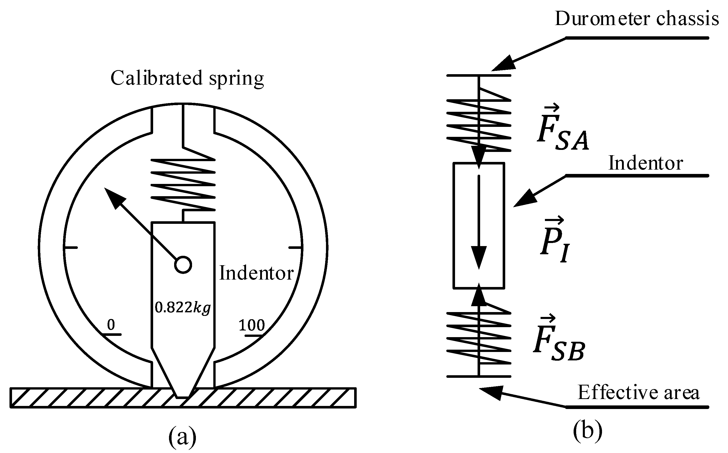
  63. ASTM D2240-15; Standard Test Method for Rubber Property—Durometer Hardness. American Society for Testing and Materials: West Conshohocken, PA, USA, 2021. [CrossRef]
  64. Mohan, R.; Das, B.N.; Sundaresan, R. Effect of hardness and surface roughness on slip resistance of rubber. J. Test. Eval. 2015, 43, 1574–1586. [Google Scholar] [CrossRef]
  65. Larson, K. Can You Estimate Modulus from Durometer Hardness for Silicones? Dow Corning: Midland, MI, USA, 2016; pp. 1–6. [Google Scholar]
  66. Heindl, R.A.; Mong, L.E. Young’s modulus of elasticity, strength, and extensibility of refractories in tension. J. Res. Natl. Bur. Stand. 1936, 17, 463. [Google Scholar] [CrossRef]
  67. Shen, C.; Rawls, H.R.; Esquivel-Upshaw, J. Phillips’ Science of Dental Materials; Elsevier: Amsterdam, The Netherlands, 2021. [Google Scholar]
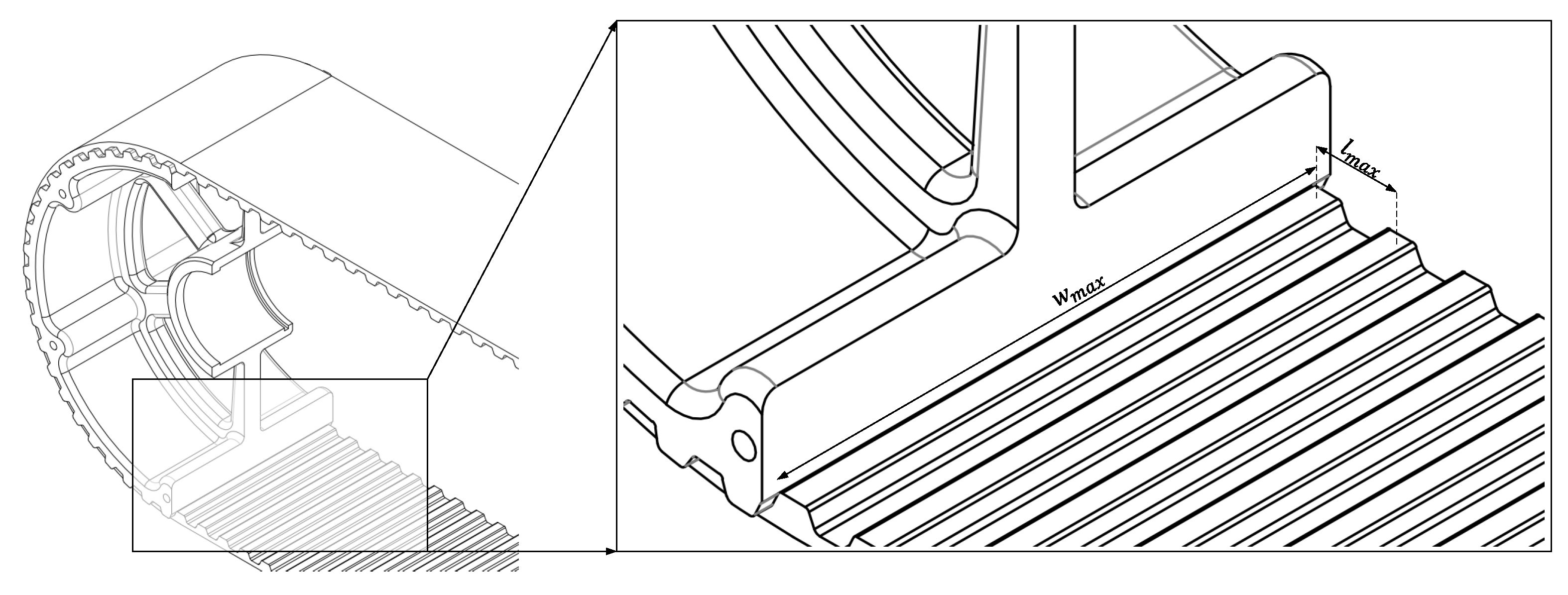
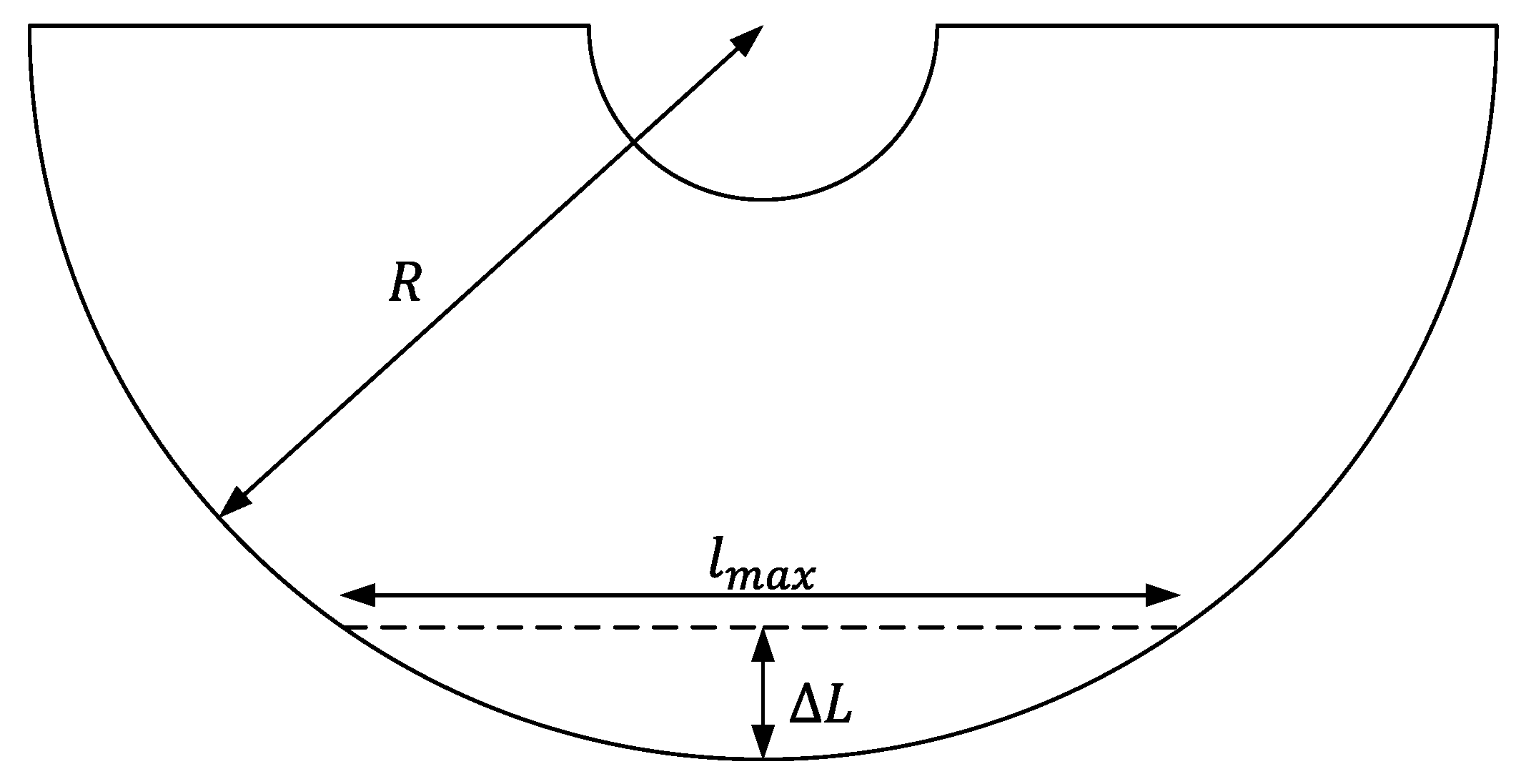
Figure 1. Force analysis in the no-slip state and zero acceleration.
Applsci 12 06605 g001
Figure 2. Equivalent model of rubber track pad coating belt.
Applsci 12 06605 g002
Figure 3. Basic scheme of a shore durometer (a) and the equivalent model of its principle (b).
Applsci 12 06605 g003
Figure 4. CAD model of rubber tracking belt and timing pulleys.
Applsci 12 06605 g004
Figure 5. The displacement ( Δ L ) of rubber track belt.
Applsci 12 06605 g005
Figure 6. Prototype of PV cleaning robot.
Applsci 12 06605 g006
Figure 7. Relationship between adhesive coefficient and tilted angle.
Applsci 12 06605 g007
Figure 8. Relationship between adhesive coefficient and shore hardness.
Applsci 12 06605 g008
Table 1. Physical parameters of rubber wheel crawler.
ParametersValueParametersValue
MaterialPolyurethane (PU)Coated materialSynthetic/Red rubber
Tooth profileT10Coated trackpadCuboidal back profile
Width75 mmShore hardnessA35/A40
Length1690 mmDeep recessedOnly block/Zigzag pattern
Thinkness20 mm
Table 2. Maximum value of tilted angle for each case of material and shore hardness.
MaterialShore HardnessMaximum Tilted Angle
Synthetic rubberShore A3030 °
Red rubber28 °
Synthetic rubberShore A3525 °
Red rubber21 °
Synthetic rubberShore A4018 °
Red rubber15 °
Synthetic rubberShore A4511 °
Red rubber7 °
Synthetic rubberShore A503 °
Red rubber0 °
Table 3. Maximum value of shore hardness for each case of material and tilted angle.
MaterialTilted AngleMaximum Shore Hardness
Synthetic rubber30 ° A30
Red rubberA28
Synthetic rubber25 ° A35
Red rubberA32
Synthetic rubber20 ° A39
Red rubberA36
Synthetic rubber15 ° A42
Red rubberA40
Publisher’s Note: MDPI stays neutral with regard to jurisdictional claims in published maps and institutional affiliations.

