Abstract
This paper focuses on the soft normally open point (SNOP) which has no transformers and connects to the 10 kV distribution network through the arc suppression coil grounding mode. A mathematical model containing positive-, negative-, and zero-sequence components under AC fault is established by the circuit analysis and the sequence component decomposition. Then the voltage fluctuation mechanism at the DC side and the non-fault AC side caused by the zero-sequence voltage on the fault side is analyzed under the case without transformers. Taking the single-phase grounding fault as an example, the fluctuation formula of the DC voltage and AC voltage is deduced in detail. Based on the theoretical analysis, the zero-sequence control strategy and the sub-module improvement strategy of the modular multilevel converter (MMC) are proposed. A back-to-back SNOP simulation model is established in PSCAD/EMTDC. The simulation results verify the accuracy of the theoretical analysis, as well as the validity of zero-sequence control and MMC topology improvement strategies.
1. Introduction
The distribution network is used for supplying electricity to power users directly, but it has some problems such as low automation level, weak grid structure, and so on. With the development of photovoltaic power generation, wind power generation, electric vehicles, etc., voltage fluctuation and imbalance become more and more serious. However, traditional measures cannot solve these problems [1,2]. The soft normally open point (SNOP) is used to replace the traditional loop switch; it can control the active and reactive power flowing through the connected feeder lines, to deal with the stochastic fluctuation caused by new energy and new loads [3,4,5]. The application of SNOP can completely change the traditional power supply mode of closed-loop design and open-loop operation, and improve the controllability and flexibility of the distribution network.
SNOP can adopt different topologies. For medium voltage, the back-to-back DC distribution system which uses the modular multilevel converter (MMC) is the most feasible one. MMC has been widely used in engineering with low loss and high reliability [6,7]; it usually connects to the AC system using the transformer to isolate the fault between the AC system and the DC system. However, the transformer will increase the footprint of SNOP, which affects the compact design of SNOP, so the transformerless design should be considered [8].
In the situation without the transformer, the zero-sequence component between the SNOP and the AC distribution system cannot be isolated naturally. The zero-sequence component is transferred through the SNOP from the fault supply area to other supply areas, and the fault influence range is expanded. The fault characteristics of transformerless SNOP are quite different from those with transformers. Scholars have carried out extensive research on AC/DC fault characteristics of flexible DC systems with transformers. Based on the two-level voltage source converter (VSC), reference [9] analyzes the response characteristics of unipolar DC grounding faults and bipolar DC short circuit faults, and reference [10] proposes the fault location strategy and system protection strategy. Reference [11] proposes three topology structures of SNOP, and comprehensively compares their advantages and disadvantages combined with the analysis of AC/DC fault characteristics. Reference [12] analyzes the fault characteristics of the bridge arm fault, and proposes a protection strategy based on closing the sub-module (SM) bypass switch to ensure the reliable action of the AC breaker. Reference [13] studies the relevant characteristics of single-phase grounding faults in AC systems and single-pole grounding faults in DC SNOP systems with a single transformer. Reference [14] analyzes the AC and DC fault characteristics of the transformerless SNOP, and derives the analytical equations of the fault current of the post-fault converter under different working modes. References [15,16] study MMC topologies with DC fault-clearing capability, and propose a DC fault-clearing strategy for fast fault recovery. However, the fault characteristics and the control and protection of the transformerless SNOP have not been studied in depth.
SNOP is usually connected to the end of feeder lines. In this paper, the ±10 kV transformerless MMC-based SNOP connected to the 10 kV AC distribution system is taken as the research object. The novelty and contribution of this paper are as follows: (1) A mathematical model containing positive, negative, and zero sequence components under AC fault is established by the circuit analysis and the sequence component decomposition. (2) The voltage fluctuation mechanism at the DC side and the non-fault AC side caused by the zero-sequence voltage at the fault side is analyzed under the case without transformers. (3) The zero-sequence control strategy and the SM improvement strategy of the modular multilevel converter (MMC) are proposed.
The structure of this paper is as follows. Section 2 describes the system connection form and the mathematical model of the SNOP. Fault response characteristics under the traditional positive and negative sequence control are analyzed in Section 3. Characteristic analysis of the single-phase grounding fault is presented in Section 4. Section 5 elaborates the corresponding optimization strategy. In Section 6, a simulation model is established to verify the theoretical analysis result and the validity of the improved strategy. Finally, the paper is concluded in Section 7.
2. System Connection Form and Mathematical Model
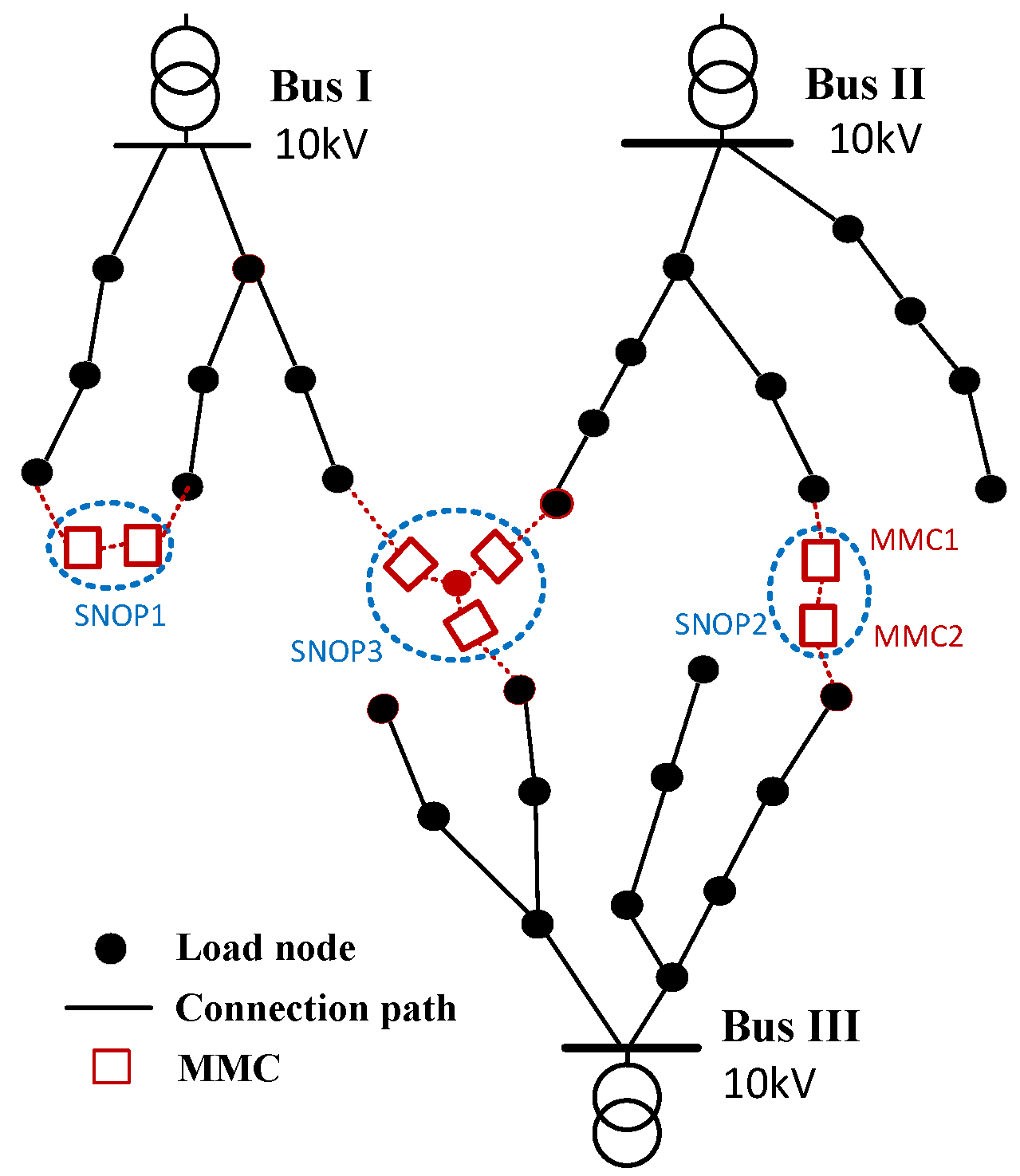
SNOP can be installed in several key locations of the distribution network. Figure 1 shows three typical ways [17]: (1) SNOP1: Connect two feeder lines in the same supply area; (2) SNOP2: Connect two feeder lines in different supply areas; (3) SNOP3: Connect multiple feed lines through multiple converters. This paper takes SNOP2 as an example.
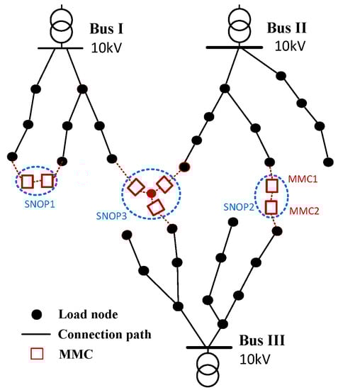
Figure 1.
System connection form of SNOP.
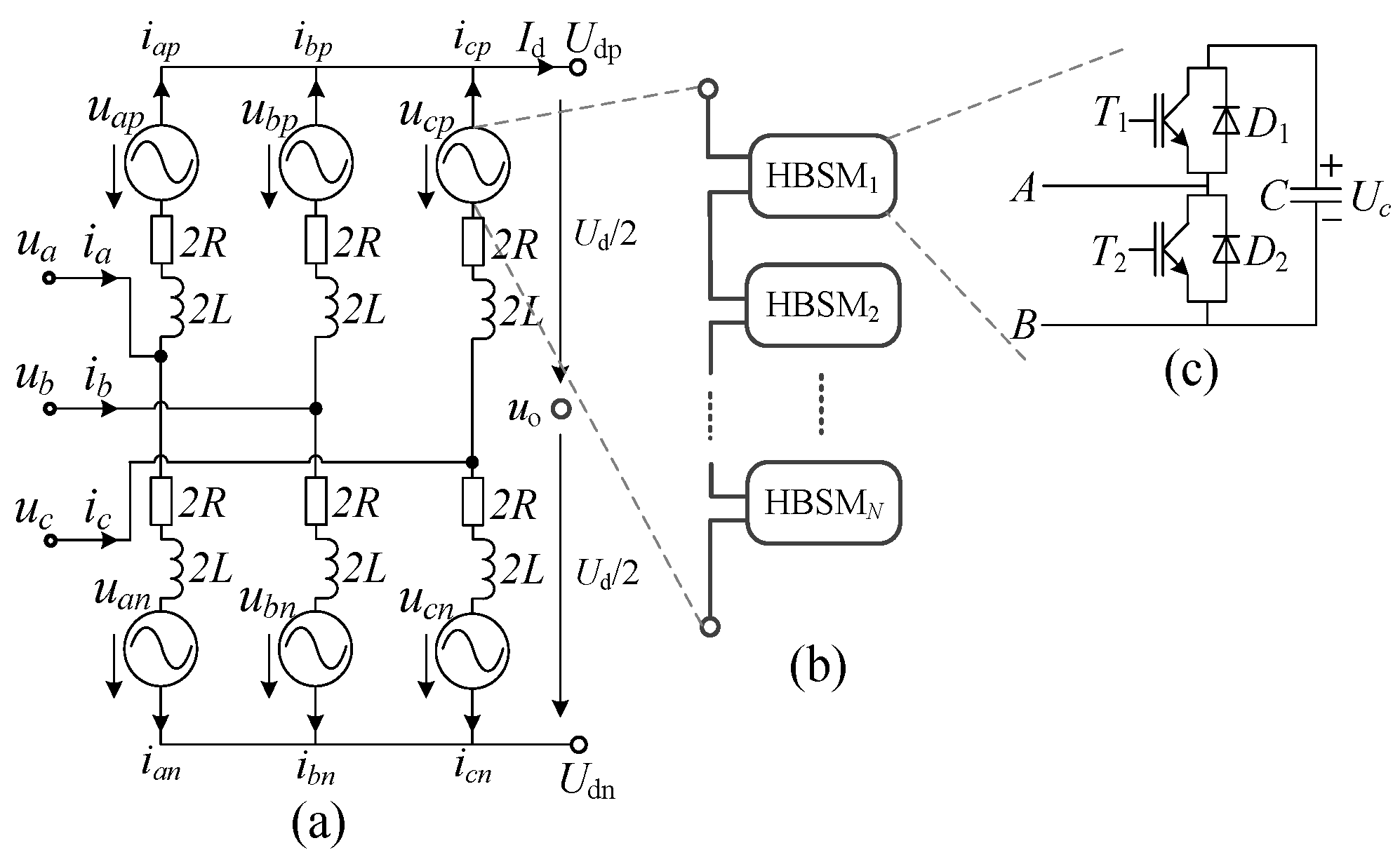
Figure 2 shows the equivalent circuit of MMC. 2L is the arm inductance, and 2R is the equivalent arm resistance. ua, ub and uc are the three-phase voltage. ia, ib and ic are the three-phase current. Ud and Id are the pole-to-pole DC voltage and DC current, respectively. Udp and Udn are the positive and negative DC voltages. The point “o” is a virtual neutral point at the DC side. ijp and ijn are the upper and lower arm currents of phase j (j = a, b, c). ujp and ujn are the output voltage of the upper and lower arm in phase j. uo is the voltage of point “o”. Figure 2c shows the structure of the half-bridge SM (HBSM).
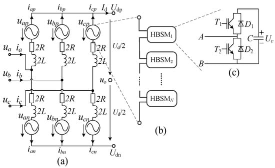
Figure 2.
Schematic diagram of MMC. (a) Equivalent circuit of MMC. (b) Diagram of bridge arm. (c) Diagram of sub-module.
According to Kirchhoff’s voltage law, we can obtain
Plus Equations (1) and (2), a new equation is as follows
where
According to the symmetrical component method, the time-varying system can be decomposed into three positive-sequence, negative-sequence, and zero-sequence independent subsystems.
According to the Equations (5)–(7), there is no uo in the positive and negative-sequence subsystems, and uo is only determined by the zero-sequence subsystem. The positive and negative-sequence mathematical models obtained through the Park transform and the Laplace transform have been mature [11], so they will not be reiterated here.
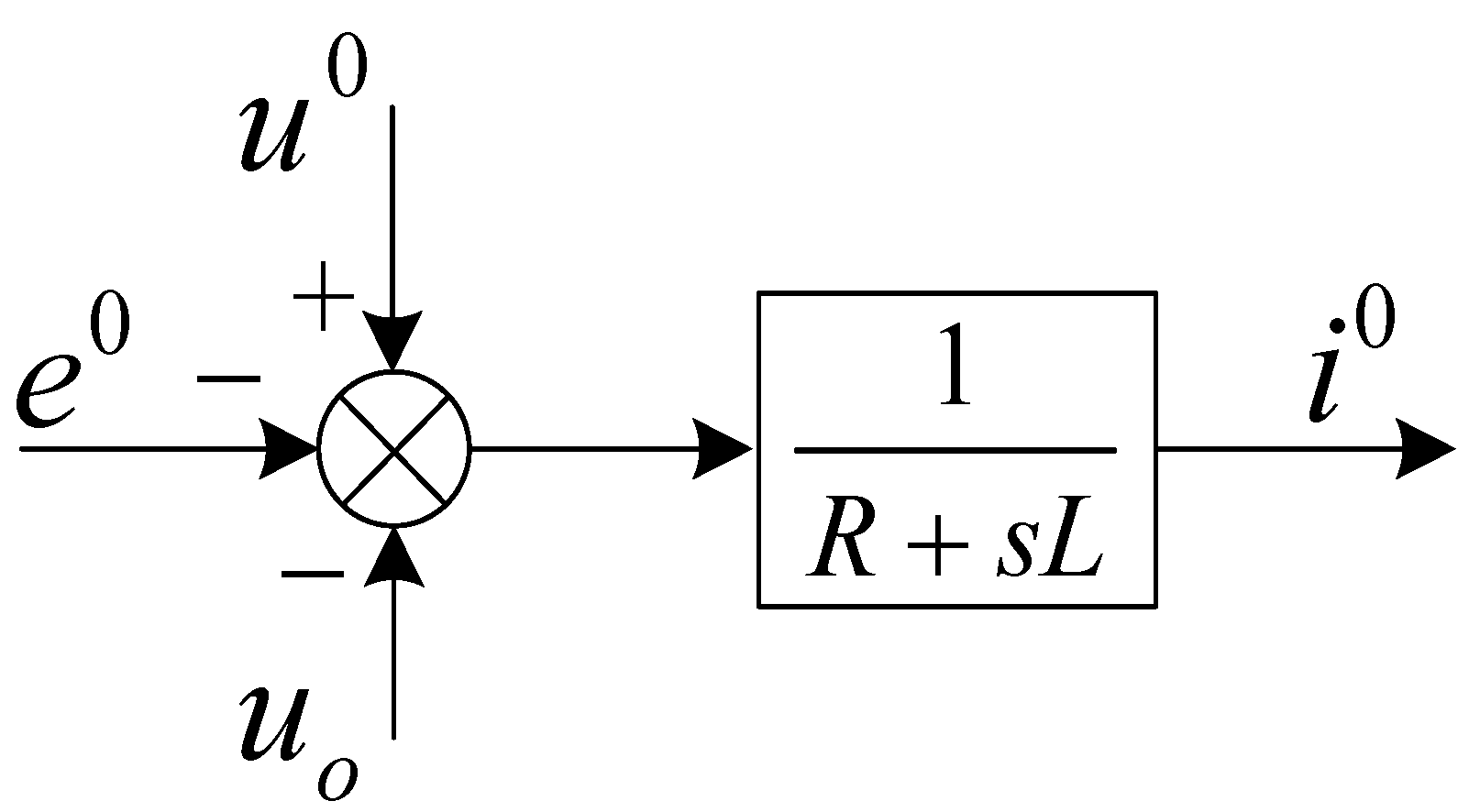
According to Equation (7), Figure 3 shows the zero-sequence model of MMC.
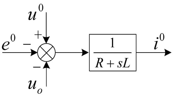
Figure 3.
Zero-sequence model of MMC.
3. Fault Response Characteristics under Traditional Positive and Negative Sequence Control
In order to realize the AC fault ride-through, the voltage-current double closed loop control strategies for the positive and negative sequence have been matured [11,18]. Whether the power or the current is controlled in the positive or negative sequence, the final instruction generated by the control loop is executed by adjusting ujp and ujn as shown in Figure 2. However, if the controller only has the positive- and negative-sequence control function, ujp and ujn will only contain positive- and negative-sequence components. So ej in Equation (4) only contains positive- and negative-sequence components, without the zero-sequence component, that is, e0 = 0. Then, under the traditional positive- and negative-sequence control strategy, Equation (7) can be rewritten as
When symmetrical or asymmetrical grounding faults occur in the 10 kV distribution system with arc suppression coil grounding, the fault current is small, and i0 ≈ 0. Therefore, Equation (8) can be simplified as follows.
It can be seen from Equation (9) that the zero-sequence component caused by the AC asymmetrical fault leads to the fluctuation of uo. Since Udp and Udn are (0.5Ud + uo) and (uo − 0.5Ud), respectively, the non-zero state of uo leads to the fluctuation of the positive DC voltage and negative DC voltage, but the pole-to-pole DC voltage keeps constant.
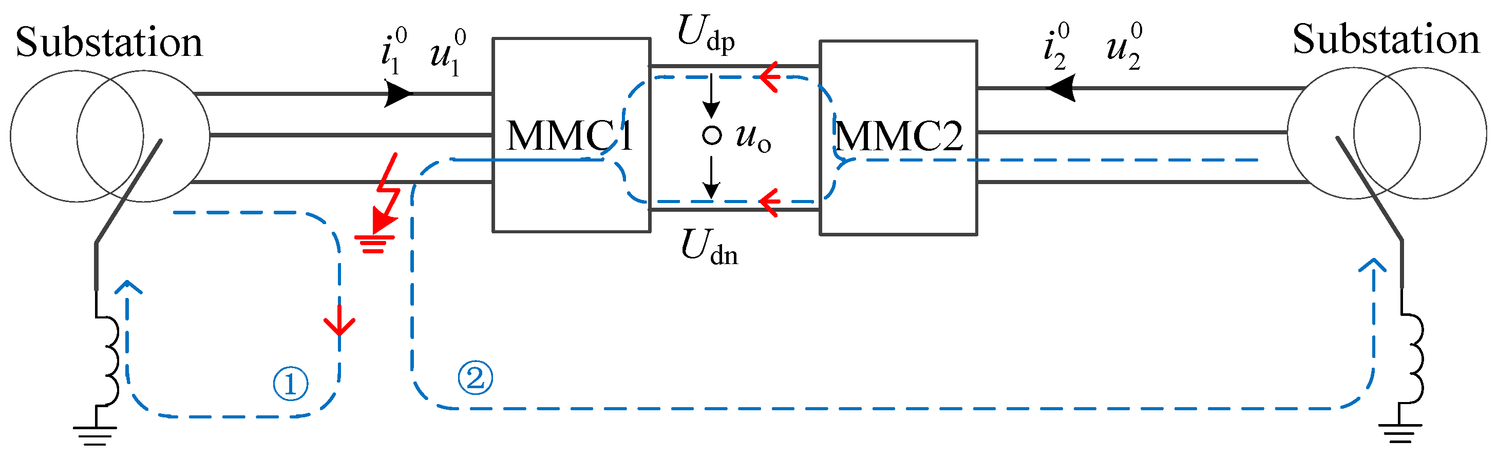
Since the MMC1 and MMC2 shown in Figure 1 are connected back to back, the “o” point can be regarded as a common virtual DC neutral point. It is known from the reverse calculation of Equation (8) that if MMC2 is only configured with the positive- and negative-sequence controller, the AC voltage of MMC2 will result in the zero-sequence component when the asymmetrical grounding fault occurs on the AC side of MMC1 which leads to the “o” point voltage offset. Furthermore, the amplitude of the zero-sequence component is almost the same as the MMC1 side if the zero-sequence impedance is neglected. The introduction of zero-sequence components leads to fluctuation in the AC voltage on the MMC2 side. In this way, the asymmetric grounding fault on the MMC1 side is transferred to the supply area where MMC2 is located, resulting in the expansion of the fault.
The zero-sequence component has two paths as shown in Figure 4. Path ① is the loop from the fault point to the neutral point of supply area 1, similar to the traditional AC grounding fault. In path ②, the zero-sequence current flows through the fault point, the neutral point of supply area 2 and SNOP.
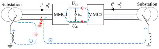
Figure 4.
Zero-sequence current path.
In the 10 kV distribution system with arc suppression coil grounding, it is allowed to run temporarily for two hours under the single-phase grounding fault, to improve the reliability of the power supply. In this case, if SNOP is not blocked, the two supply areas connected to MMC1 and MMC2 will experience the grounding fault together for two hours. The safety and stability of the whole distribution system will be greatly impacted.
4. Characteristic Analysis of Single-Phase Grounding Fault
In order to further analyze the asymmetric fault characteristics of the system quantitatively, the phase C metallic grounding fault which happens on the feeder connected to MMC1 in Figure 1, is taken as an example. Assuming that the three-phase voltage is symmetrical before faults, the amplitude of the rated phase-to-ground voltage is Um, and the initial phase of phase A is φ1. After the grounding fault occurs, the voltage of the fault phase is zero, and the voltage of the non-fault phase rises to line-to-line voltage.
Adopting the symmetrical component method, the positive-, negative-, and zero-sequence voltages are given as follows.
It can be seen from Equation (11) that when phase C is in a grounding fault, the amplitude of the positive- and zero-sequence component is the same, which is the rated phase-to-ground voltage. Combining Equation (9), the following equation can be obtained.
Making the voltage modulation ratio k (k < 1) as follows, the positive DC voltage Udp and the negative DC voltage Udn is
It can be seen from Equation (14) that the positive and negative DC voltages fluctuate in power frequency, and the amplitude of the fluctuation is equal to the AC phase voltage Um. Although the positive and negative poles have voltage fluctuation, the fluctuation is still in the range of the rated DC voltage, and there is no polarity reversal. The maximum and minimum value of the positive DC voltage is 0.5(1 + k)Ud and 0.5(1 − k)Ud. The maximum and minimum value of the negative DC voltage is −0.5(1 + k)Ud and −0.5(1 − k)Ud. It is obvious that the maximum voltage of the positive and negative pole is close to the rated pole-to-pole voltage, which has an impact on the safe operation of the system.
For MMC2, due to the voltage fluctuation of uo in Equation (12), it is known from Equations (8) and (9) that the zero-sequence voltage shown in Equation (12) will be introduced into the AC system of MMC2. Before the grounding fault in MMC1 happens, the AC system of MMC2 only contains positive-sequence components. (In order to simplify the analysis, it is assumed that the rated phase voltage amplitude of MMC2 is the same as that of MMC1.)
where φ2 is the initial phase. Using the inverse transform of the symmetric component method, the AC voltage of MMC2 can be calculated as follows, when the AC system of MMC1 is in fault.
where a = ej120.
- (1)
- If φ1 = φ2, that is, the phase difference of the AC system between MMC1 and MMC2 is almost zero, then
Comparing Equations (10) and (17), it is obvious that the AC voltage of MMC2 is equal to MMC1 (the fault side), when neglecting some impedance in the zero-sequence circuit loop. It seems that the AC side of MMC2 has a grounding fault in phase C.
- (2)
- If φ1 ≠ φ2, then the AC voltage of MMC2 will change with the phase difference. In an urban distribution network, the phase difference among supply areas connected to the SNOP is generally not large, e.g., −15°~15°. Therefore, although the AC voltage of MMC2 is different from Equation (17), it is still close. Equation (17) still has the reference value. It is necessary to point out that if the fault type is the two-phase fault or the single-phase resistance grounding fault, the theoretical calculation and deduction method presented in this section can also be used, which facilitates understanding the effect of the asymmetrical fault on the voltage characteristics of the supply areas quantitatively.
5. Optimization Method
According to the analysis above, the optimization methodology and steps are shown in Figure 5, and the detailed analysis is described as follows.
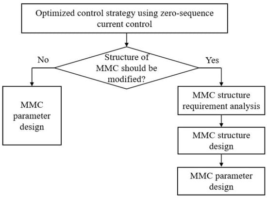
Figure 5.
Optimization methodology and step.
5.1. Control Strategy Optimization
From the theoretical deduction above, it can be seen that the fluctuation of DC voltage in the power frequency is caused by the non-zero value of the “o” point voltage uo. In order to suppress the transfer of the zero-sequence component from one side to another through the SNOP and reduce the effect range of the fault, it is necessary to restrict uo to zero by means of corresponding control strategies. It can be seen from Equation (7) and Figure 3 that only if e0 is controlled as the following equation, can the purpose of DC voltage fluctuation suppression be achieved effectively.
On the other hand, the zero-sequence current will flow through the bridge arm, and cause the overheating of power electronic devices, especially in the case of large zero-sequence currents. Therefore, the zero-sequence current control needs to be added.
The zero-sequence current is in AC form. Based on the existing proportional resonant (PR) controller [19,20] which can realize the non-error adjustment of alternating quantities, this paper designs the zero-sequence control loop as shown in Figure 6, according to the mathematical relationship among the variables in Equation (18). Where Kp is the proportional coefficient, KR is the resonance coefficient; ω0 is the angular frequency used to control the AC signal, ωc is the cut-off angular frequency. In order to eliminate the zero-sequence current component, the zero-sequence current reference value of the PR controller is set to zero. Meanwhile, in order to suppress the zero-sequence voltage caused by the voltage fluctuation of “o” point, the zero-sequence component u0 of the AC voltage is used as the feed-forward value.
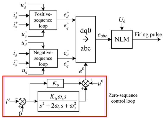
Figure 6.
Optimized control strategy of MMC.
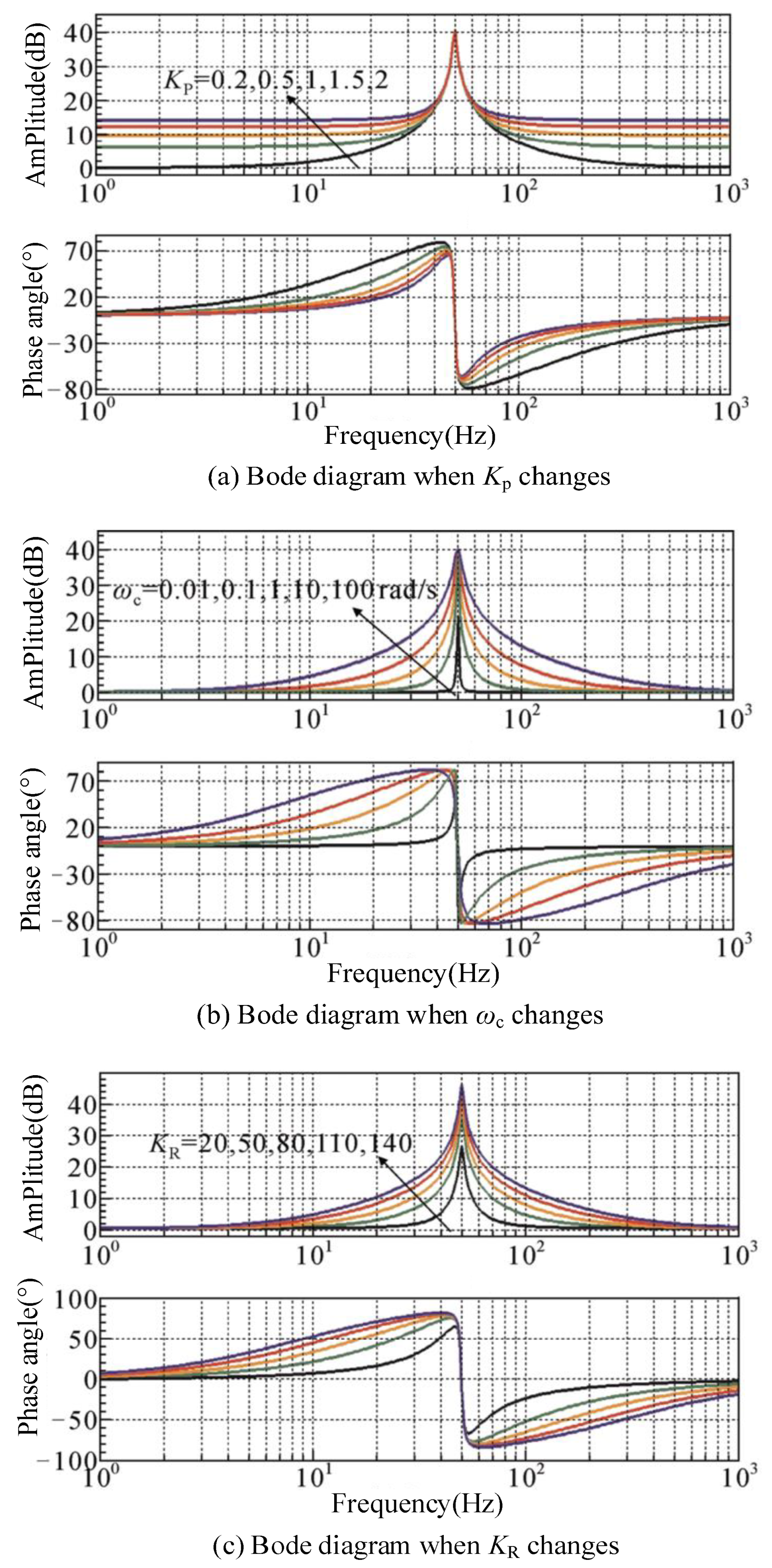
In Figure 7a, with the increase in the Kp value, the amplitude margin at the resonant frequency does not change significantly, while the gain in other frequency bands increases, indicating that too large a Kp value will weaken the comparative advantage of the resonant link; that is, indirectly affect the bandwidth and stability of the controller. Different ωc values in Figure 7b have little effect on the gain of resonant frequency point, but the control system bandwidth is positively correlated with it, thus enhancing the controller’s ability to quickly track the sinusoidal alternating quantity and improving the system’s robustness to grid frequency fluctuations. In Figure 7c, with the increase in KR value, the gain at the resonant frequency of the controller increases, and the effect of eliminating the steady-state error is achieved. Therefore, the PR controller parameter design needs to take into account the interaction between the dynamic and static performance of the system. The regulation of its parameters is: Adjust the proportional coefficient Kp and the resonant coefficient KR to meet the system stability, dynamic and static performance; Adjust the cut-off angular frequency ωc to suppress the disturbance of frequency fluctuation to the converter.
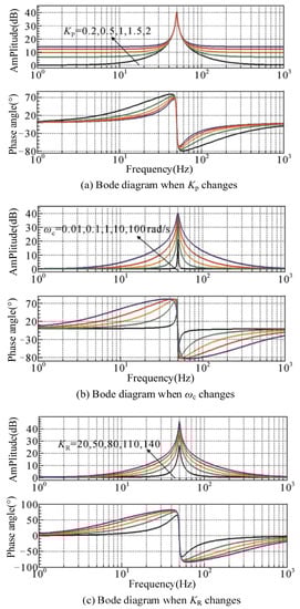
Figure 7.
Influence of parameter variation on amplitude frequency characteristics of PR controller.
5.2. Topology Optimization Requirement
After adding the zero-sequence control loop, the arm voltage of MMC will introduce the zero-sequence component. The vector superposition of positive, negative, and zero sequence voltage in the arm is the actual output requirement of the arm. Therefore, it is necessary to consider the following issues: The output voltage capability of each arm is limited, which is determined by the SM structure, SM capacitor voltage and the number of SMs. When the zero-sequence voltage is added, can the existing MMC arm output the required voltage?
In fact, when the positive, negative, and zero sequence currents are effectively limited within the allowable range, the voltage drop on the arm inductance and resistance can be ignored, so the AC voltage of the converter valve is approximately the same as uj. The output voltage of each arm is shown below.
Each phase amplitude of uj is different under different faults. Taking the single-phase grounding fault as an example, the maximum and minimum arm voltages of phase A and B are presented as Equations (20) and (21), by bringing Equation (10) into the Equation (19). And the arm voltage of the phase C is almost 0.5 Ud.
If SNOP is required to control all the sequence components, each arm must contain (0.87 k − 0.5)N SMs which are able to output a negative level. At the same time, the number of SMs able to output a negative level should be larger than (0.87 k + 0.5)N, where N = Ud/Uc, and Uc is the SM capacitive voltage. In the steady state, the voltage modulation ratio k is usually 0.8~0.95. If k = 0.85, the number of negative levels is 0.24 N, and the number of positive levels is 1.24 N.
5.3. Optimized Topology Structure (Hybrid MMC)
According to the analysis above, since HBSM only has positive and zero level output capability, the pure half-bridge MMC (H-MMC) cannot meet the mentioned requirements, and the SM with negative level needs to be adopted. At present, there are many SMs with a negative level. In this paper, the full-bridge SM (FBSM) is taken as an example. FBSM can output three levels: positive, zero, and negative [21]. In order to satisfy the purpose of zero-sequence suppression and save investment costs, a hybrid MMC structure composed of HBSMs and FBSMs can be adopted. According to the analysis in the previous section, each arm needs (0.87 k − 0.5)N FBSMs and N HBSMs, without considering the SM redundancy.
In the 10 kV distribution system with arc suppression coil grounding, the phase voltage rise caused by a single-phase grounding fault is the most serious. Therefore, the hybrid MMC based on the method above can satisfy the requirements of suppressing the zero-sequence component of the system under other fault types.
In order to reduce the investment cost of adding and replacing SMs, it can be seen from Equation (19) that the number of SMs can be reduced by decreasing the DC voltage during AC faults. However, given the limited length of this article, no explanation will be given here. The control strategy shown in Figure 6 is applicable to both cases.
6. Simulation Analysis
6.1. Simulation Parameter
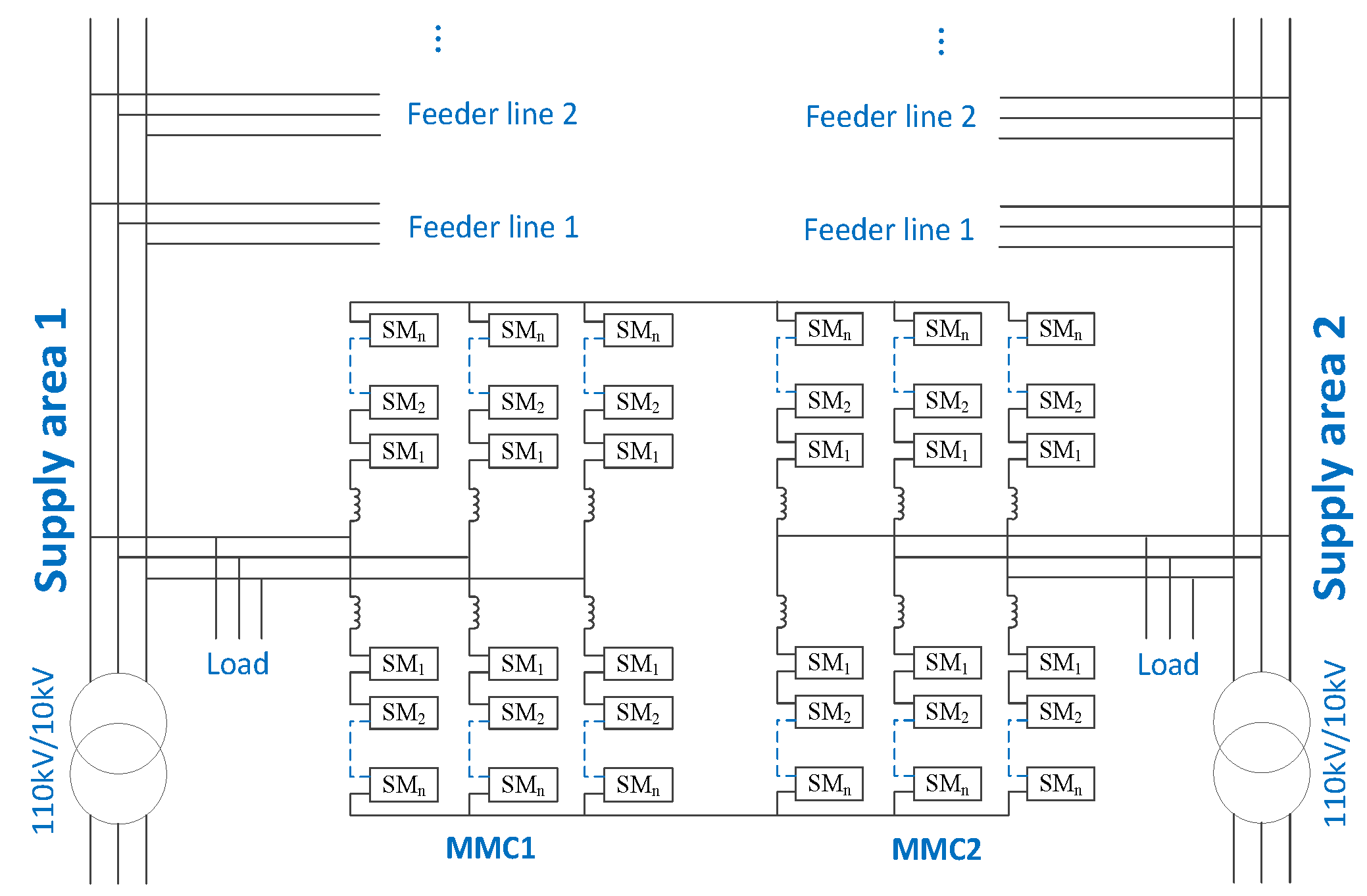
A simulation model shown in Figure 8 is built in the electromagnetic transient simulation software PSCAD/EMTDC. SNOP contains two H-MMCs. The rated capacity of each H-MMC is 10 MVA. The rated DC voltage of SNOP is ±10 kV. According to the characteristics of different loads, the static load model “Fixed Load” is used. Supply area 1 and 2 both adopt the arc suppression coil grounding, and the grounding inductance is 0.78 H. The two 110 kV AC systems adopt the same short circuit ratio SCR = 5. H-MMC has twenty-four HBSMs in each arm, and two HBSMs are redundant. The arm inductance is 3 mH. The rated DC voltage of HBSM is 0.91 kV. The capacitance of HBSM is 5000 μF.

Figure 8.
Schematic diagram of simulation model.
6.2. System Response Characteristics of Traditional Control Strategy
In the steady state, MMC1 adopts a constant active power and constant reactive power control strategy, MMC2 adopts constant DC voltage and a constant reactive power control strategy. At t = 0.8~0.9 s, the AC system connected to MMC1 happens an A-phase grounding fault.
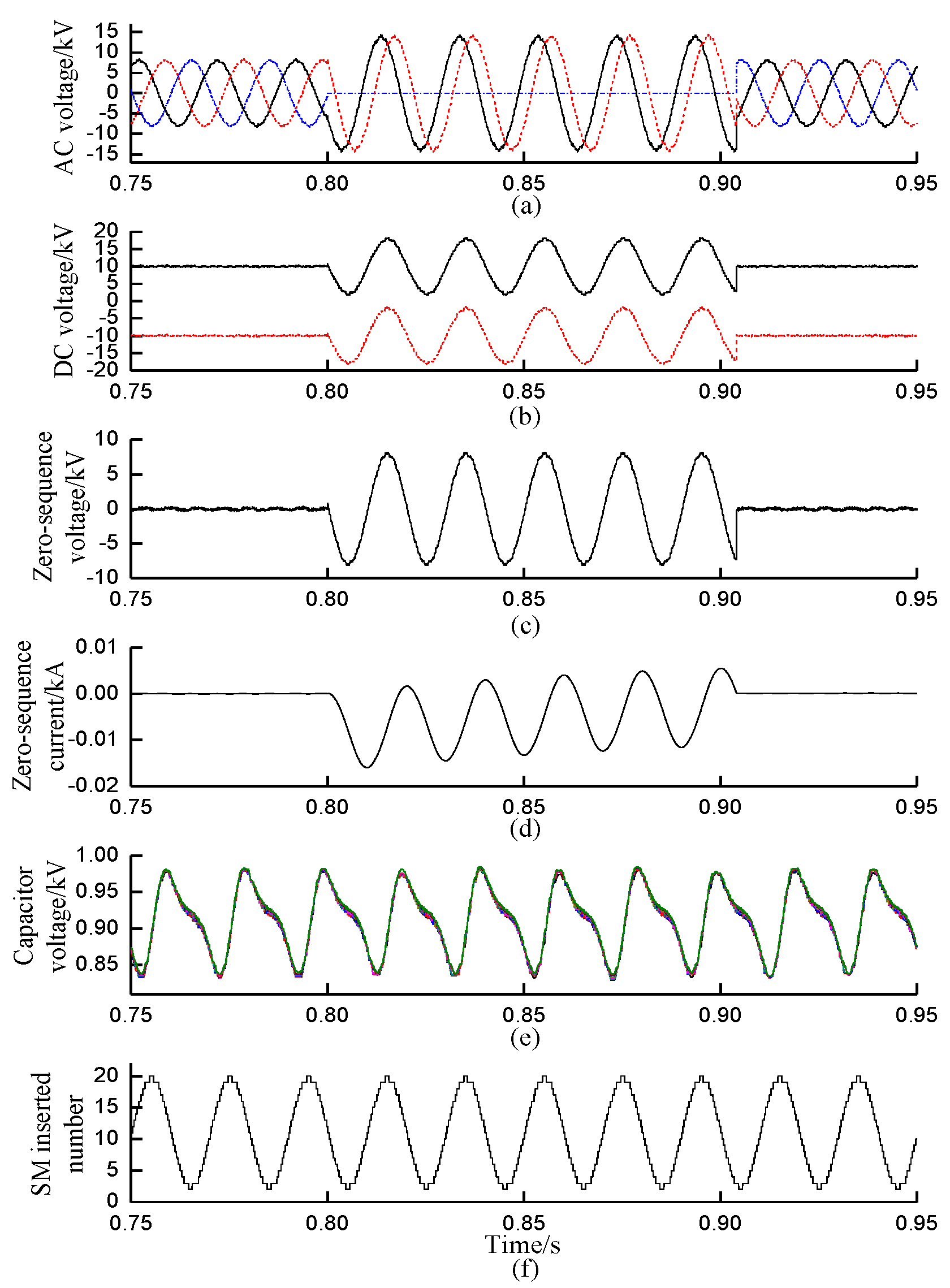
Figure 9a–f shows the response waveforms of three-phase AC voltage, positive and negative DC voltage, AC zero-sequence voltage, AC zero-sequence current, SM capacitor voltage and the inserted SM number of the upper arm in phase A on the MMC1 side. It can be seen from Figure 9 that the voltage of phase A drops to zero quickly after the fault, and the voltages of phase B and C increase to 1.73 times the rated phase voltage. The zero-sequence voltage amplitude is equal to the rated phase voltage. The positive and negative DC voltages contain the fundamental frequency component whose amplitude and phase are the same as the zero-sequence voltage component, which proves the correctness of Equation (12). Since the AC distribution system is the arc suppression coil grounding, the zero-sequence current is less than 16 A, as shown in Figure 9d. During the whole fault period, because the control system only contains positive and negative sequence control, and the zero-sequence power is unchanged, so the SM switching and SM capacitor voltage stay the same.
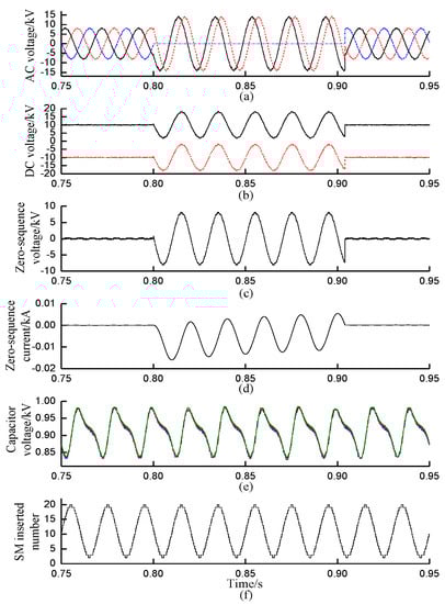
Figure 9.
Fault response characteristics of MMC1 before optimization. (a) Three-phase AC voltage (blue is A-phase, black is B-phase, red is C-phase). (b) Positive and negative DC voltage (black is positive DC voltage, red is negative DC voltage). (c) AC zero-sequence voltage. (d) AC zero-sequence current. (e) SM capacitor voltage. (f) Inserted SM number of the upper arm in phase A on the MMC1.
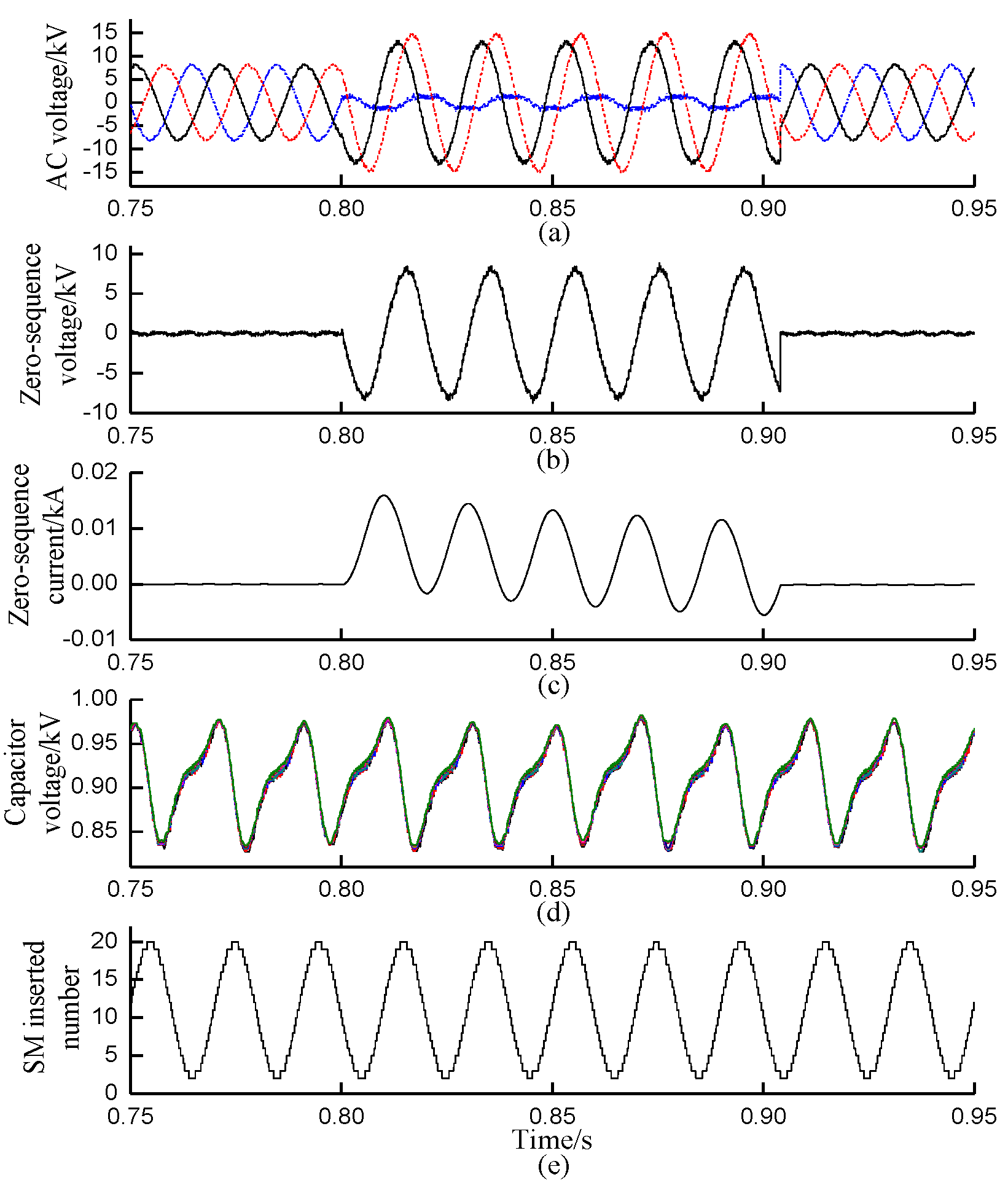
Figure 10a–e shows the response waveforms of the three-phase AC voltage, the AC zero-sequence voltage, the AC zero-sequence current, the SM capacitor voltage and the inserted SM number of the upper arm in phase A on the MMC2 side. It can be seen from Figure 10 that the voltage of phase A drops to 1.5 kV, the voltages of phase B and C increase to 13.2 kV and 14.8 kV after the fault. The voltage characteristics are similar to those of MMC1, and the correctness of the above theoretical derivation is demonstrated. The zero-sequence voltage amplitude on the MMC2 side is similar to MMC1. The zero-sequence current is small: its amplitude is less than 16 A. During the whole fault period, the SM switching and SM capacitor voltage of MMC2 stay the same. Its principle is the same as MMC1.
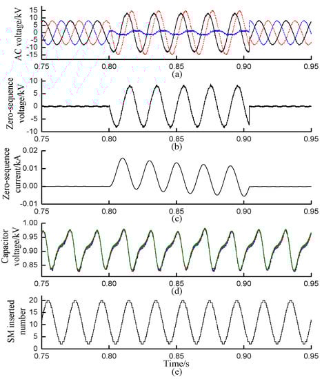
Figure 10.
Fault response characteristics of MMC2 before optimization. (a) Three-phase AC voltage (blue is A-phase, black is B-phase, red is C-phase). (b) AC zero-sequence voltage. (c) AC zero-sequence current. (d) SM capacitor voltage. (e) Inserted SM number of the upper arm in phase A on the MMC2.
6.3. System Response Characteristics after Optimization
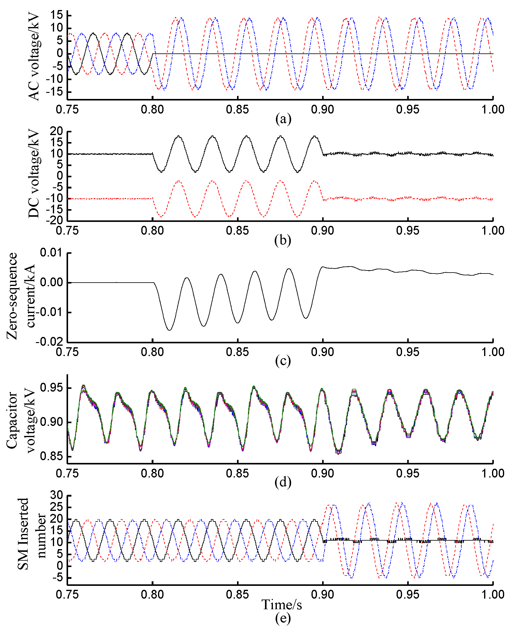
In steady-state operation, the rated AC voltage of the distribution network is 10kV, and the DC voltage of SNOP is ±10 kV. Therefore, the voltage modulation ratio k is 0.82. According to the analysis above, each arm of the hybrid MMC contains twenty-two HBSMs and five FBSMs, and the capacitance is the same. At t = 0.8 s, an A-phase grounding fault happens on the AC side of MMC1. At t = 0.9 s, the zero-sequence control loop is put into operation.
Figure 11 shows the response waveforms of three-phase AC voltage, positive and negative DC voltage, AC zero-sequence current, SM capacitor voltage and the inserted SM number of the upper arm on the MMC1 side. It can be seen from Figure 11 that the DC voltage fluctuation of the positive and negative poles is suppressed immediately after the zero-sequence control loop is put into operation. The zero-sequence current is suppressed to near zero, and the SM capacitor voltage is stabilized near the rated value. The inserted number of phase A remains around 11, the maximum inserted number of phase B and C is 27, and the minimum is −5.
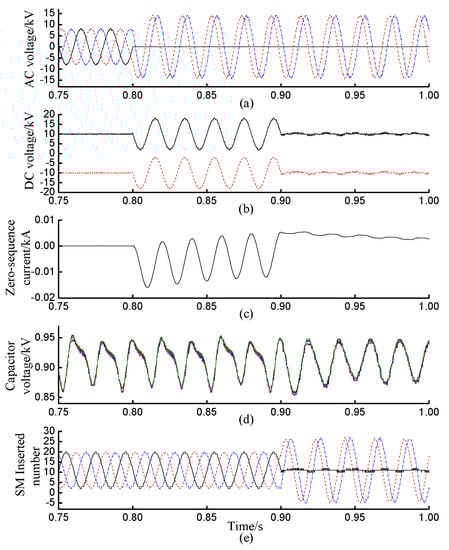
Figure 11.
Fault response characteristics of MMC1 after optimization. (a) Three-phase AC voltage (black is A-phase, red is B-phase, blue is C-phase). (b) Positive and negative DC voltage (black is positive DC voltage, red is negative DC voltage). (c) AC zero-sequence current. (d) SM capacitor voltage. (e) Inserted SM number of the upper arm on the MMC1 (black is A-phase, red is B-phase, blue is C-phase).
Figure 12 shows the response waveforms of the three-phase AC voltage, the AC zero-sequence voltage and the AC zero-sequence current on the MMC2 side. It can be seen from Figure 12 that the zero-sequence voltage component and zero-sequence current component are effectively suppressed after the zero-sequence control loop is put into operation. The AC voltage of the supply area connected to MMC2 recovers to the three-phase symmetrical stable state, which indicates that the fault in the supply area connected to MMC1 will not affect the supply area connected to MMC2, and the fault range is effectively limited.
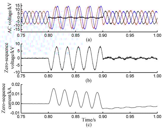
Figure 12.
Fault response characteristics of MMC2 after optimization. (a) Three-phase AC voltage (black is A-phase, red is B-phase, blue is C-phase). (b) AC zero-sequence voltage. (c) AC zero-sequence current.
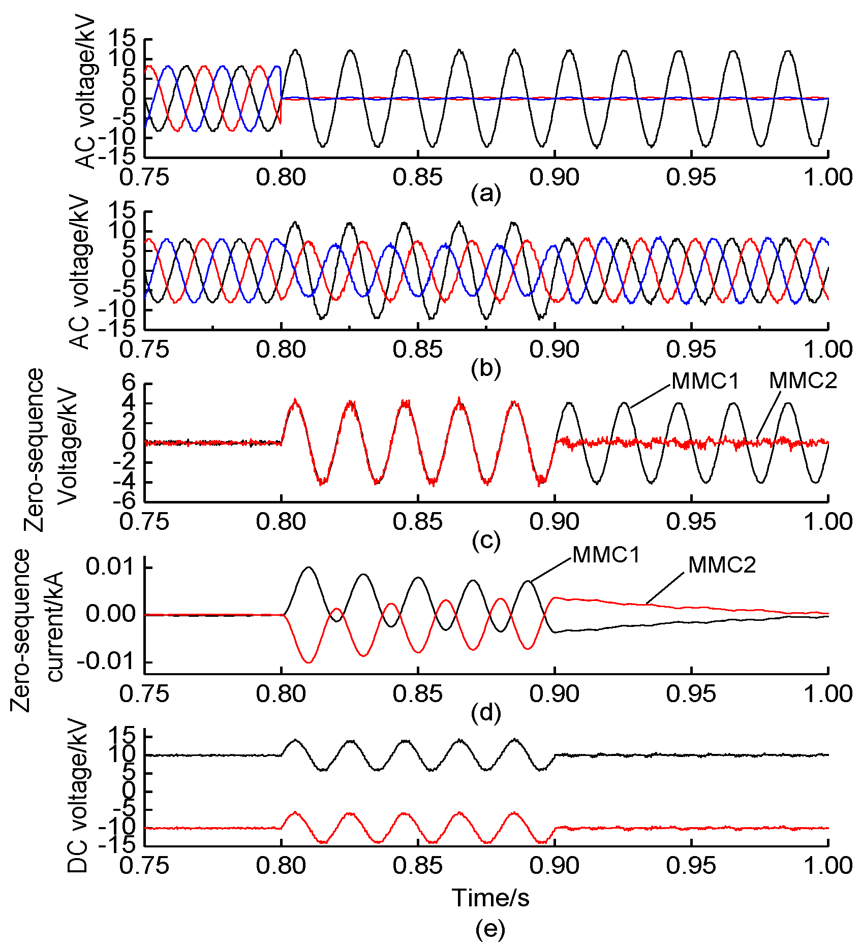
At t = 0.8 s, a two-phase grounding fault happens at phase B and C on the AC side of MMC1. At t = 0.9 s, the zero-sequence control loop is put into operation. Figure 13 shows the response waveforms of the three-phase AC voltage of MMC1, the three-phase AC voltage of MMC2, the zero-sequence voltage of MMC1 and MMC2, the zero-sequence current of MMC1 and MMC2, and the positive and negative DC voltage. It can be seen that the DC voltage fluctuation is suppressed immediately after the zero-sequence control loop is put into operation. The zero-sequence voltage of MMC2 and the zero-sequence current are suppressed to near zero.

Figure 13.
Fault response characteristics of two-phase grounding fault. (a) Three-phase AC voltage of MMC1 (black is A-phase, red is B-phase, blue is C-phase). (b) Three-phase AC voltage of MMC2 (black is A-phase, red is B-phase, blue is C-phase). (c) AC zero-sequence voltage of MMC1 and MMC2 (black is MMC1, red is MMC2). (d) AC zero-sequence current of MMC1 and MMC2 (black is MMC1, red is MMC2). (e) Positive and negative DC voltage (black is positive DC voltage, red is negative DC voltage).
7. Conclusions
Through theoretical analysis and formula derivation, this paper reveals the intrinsic mechanism of the DC voltage fluctuation and the non-fault AC voltage fluctuation caused by the zero-sequence component on the AC fault side of SNOP without the connection transformer. The zero-sequence control strategy and the SM improvement strategy of MMC are proposed to suppress the transferring of the zero-sequence component between AC and DC. The following conclusions were drawn:
- (1)
- When asymmetrical faults such as a single-phase grounding occur, the zero-sequence component will be directly superimposed on the positive and negative DC voltage, which causes the power frequency fluctuation in positive and negative DC voltage. At the same time, the zero-sequence component is transferred to the non-fault supply area through SNOP, which causes the AC voltage fluctuation of the non-fault system. The voltage characteristics of the non-fault supply area are related to the system parameters, the voltage amplitude and phase difference of the supply areas.
- (2)
- Based on the formula derivation, an improved scheme of PR controller based zero-sequence control loop and hybrid MMC topology with added FBSM is proposed. The zero-sequence control loop and hybrid MMC are designed for the particularity of the problem described in this paper. The simulation results show that the proposed method can effectively suppress the DC voltage fluctuation and the non-fault AC voltage fluctuation, and limit the fault effect area to a certain extent, thus effectively improving the reliability of the distribution network.
Author Contributions
Conceptualization, F.X.; Data curation, X.H.; Formal analysis, Y.L.; Investigation, Z.Z. All authors have read and agreed to the published version of the manuscript.
Funding
This research received no external funding.
Acknowledgments
The authors gratefully acknowledge the financial support of the Science and Technology Project of the State Grid Zhejiang Electric Power Co., Ltd., named “Research on medium and low voltage DC networking technology and application considering optimal carbon flow (5211DS21N003)”.
Conflicts of Interest
The authors declare no conflict of interest.
References
- Ji, H.; Wang, C.; Li, P.; Ding, F.; Wu, J. Robust Operation of Soft Open Points in Active Distribution Networks with High Penetration of Photovoltaic Integration. IEEE Trans. Sustain. Energy 2019, 10, 280–289. [Google Scholar] [CrossRef]
- Fuad, K.S.; Hafezi, H.; Kauhaniemi, K.; Laaksonen, H. Soft Open Point in Distribution Networks. IEEE Access 2020, 8, 210550–210565. [Google Scholar] [CrossRef]
- Sarantakos, I.; Zografou-Barredo, N.-M.; Huo, D.; Greenwood, D. A Reliability-Based Method to Quantify the Capacity Value of Soft Open Points in Distribution Networks. IEEE Trans. Power Syst. 2021, 36, 5032–5043. [Google Scholar] [CrossRef]
- Jiang, X.; Zhou, Y.; Ming, W.; Yang, P.; Wu, J. An Overview of Soft Open Points in Electricity Distribution Networks. IEEE Trans. Smart Grid 2022, 13, 1899–1910. [Google Scholar] [CrossRef]
- Mudaliyar, S.; Mishra, S. Real-Time Coordinated Control of Low-Voltage DC Distribution Network with Soft Opening Point. IEEE Trans. Power Electron. 2021, 36, 7123–7137. [Google Scholar] [CrossRef]
- Marzo, I.; Sanchez-Ruiz, A.; Barrena, J.A.; Abad, G.; Muguruza, I. Power Balancing in Cascaded H-Bridge and Modular Multilevel Converters Under Unbalanced Operation: A Review. IEEE Access 2021, 9, 110525–110543. [Google Scholar] [CrossRef]
- Vozikis, D.; Adam, G.P.; Rault, P.; Despouys, O.; Holliday, D.; Finney, S.J. Enhanced Modular Multilevel Converter with Reduced Number of Cells and Harmonic Content. IEEE J. Emerg. Sel. Top. Power Electron. 2020, 8, 2954–2965. [Google Scholar] [CrossRef] [Green Version]
- Abdelhakim, A.; Mattavelli, P.; Yang, D.; Blaabjerg, F. Coupled-Inductor-Based DC Current Measurement Technique for Transformerless Grid-Tied Inverters. IEEE Trans. Power Electron. 2018, 33, 18–23. [Google Scholar] [CrossRef] [Green Version]
- Changizian, M.; Mizani, A.; Shoulaie, A. Proposed a New Voltage Rebalancing Method for Pole-to-Ground Fault in Bipolar Two-Level VSC-HVDC. IEEE Trans. Ind. Electron. 2022, 69, 2157–2165. [Google Scholar] [CrossRef]
- Panahi, H.; Sanaye-Pasand, M.; Niaki, S.H.A.; Zamani, R. Fast Low Frequency Fault Location and Section Identification Scheme for VSC-Based Multi-Terminal HVDC Systems. IEEE Trans. Power Deliv. 2022, 37, 2220–2229. [Google Scholar] [CrossRef]
- Morales-Caporal, R.; Pérez-Cuapio, J.; Martínez-Hernández, H. Design and Hardware Implementation of a H-Bridge Sub-module for Single-Phase 5-Level Cascaded Voltage Source Inverters. In Proceedings of the IECON 2021—47th Annual Conference of the IEEE Industrial Electronics Society, Toronto, ON, Canada, 13–16 October 2021; pp. 1–6. [Google Scholar]
- Jiang, H.; Deng, F.; Wang, Z.; Zou, Z.; Li, B.; Blaabjerg, F. Harmonic Optimization Strategy for CPS-PWM Based MMCs Under Submodule Capacitor Voltage Reduction Control. IEEE Trans. Power Electron. 2022, 37, 4288–4300. [Google Scholar] [CrossRef]
- Wang, X.; Cai, X.; Chen, Q.; Lin, B.; Xie, R. Low-Voltage Ride Through Strategy for MMC with Y₀/Y₀ Arrangement Transformer Under Single-Line-to-Ground Fault. IEEE Access 2021, 9, 60658–60667. [Google Scholar] [CrossRef]
- Marzo, I.; Barrena, J.A.; Sanchez-Ruiz, A.; Abad, G.; Muguruza, I. Reactive Power Limits of Single-Phase and Three-Phase DC-Link VSC STATCOMs under Negative-Sequence Voltage and Current. In Proceedings of the IECON 2021—47th Annual Conference of the IEEE Industrial Electronics Society, Toronto, ON, Canada, 13–16 October 2021; pp. 1–8. [Google Scholar]
- Zhang, Y.; Zhang, J.; Deng, F.; Xu, Z.; Zhao, J. Hybrid Modular Multilevel Converter with Self-Balancing Structure. IEEE Trans. Ind. Appl. 2021, 57, 5039–5051. [Google Scholar] [CrossRef]
- Tao, J.; Wang, C.; Wang, Y.; Xu, T.; Nie, X.; Wei, Z. A Novel Symmetrical MMC Submodule Topology with DC Fault Ride-through Capability. In Proceedings of the 2021 IEEE 12th Energy Conversion Congress & Exposition–Asia (ECCE-Asia), Singapore, 24–27 May 2021; pp. 1099–1104. [Google Scholar]
- Patro, S.; Shukla, A. Control and Derived Topologies of Parallel Hybrid Converter. IEEE Trans. Ind. Appl. 2021, 57, 598–613. [Google Scholar] [CrossRef]
- Lai, J.; Yin, X.; Yin, X.; Ullah, Z.; Jiang, L.; Wang, Z. Improved Comprehensive Control of Modular Multilevel Converter under AC/DC Grid Faults and Harmonic Operation Conditions. IEEE Trans. Power Electron. 2021, 36, 6537–6556. [Google Scholar] [CrossRef]
- Parvez, M.; Elias, M.F.M.; Rahim, N.A.; Blaabjerg, F.; Abbott, D.; Al-Sarawi, S.F. Comparative Study of Discrete PI and PR Controls for Single-Phase UPS Inverter. IEEE Access 2020, 8, 45584–45595. [Google Scholar] [CrossRef]
- Isik, S.; Alharbi, M.; Bhattacharya, S. An Optimized Circulating Current Control Method Based on PR and PI Controller for MMC Applications. IEEE Trans. Ind. Appl. 2021, 57, 5074–5085. [Google Scholar] [CrossRef]
- Noroozi, M.; Akbari, A.; Abrishamifar, A. A 5-level modified full-bridge stand-alone inverter with reduced number of switches. Int. Trans. Electr. Energ. Syst. 2018, 28, 547–558. [Google Scholar] [CrossRef]


Publisher’s Note: MDPI stays neutral with regard to jurisdictional claims in published maps and institutional affiliations. |
© 2022 by the authors. Licensee MDPI, Basel, Switzerland. This article is an open access article distributed under the terms and conditions of the Creative Commons Attribution (CC BY) license (https://creativecommons.org/licenses/by/4.0/).