Article

Incorporation of Torsion Springs in a Knee Exoskeleton for Stance Phase Correction of Crouch Gait

by
Katy Baker Bumbard
,
Harold Herrington
,
Chung-Hyun Goh
* and
Alwathiqbellah Ibrahim
Department of Mechanical Engineering, The University of Texas at Tyler, Tyler, TX 75799, USA
*
Author to whom correspondence should be addressed.
Appl. Sci. 2022, 12(14), 7034; https://doi.org/10.3390/app12147034
Submission received: 28 May 2022 / Revised: 1 July 2022 / Accepted: 10 July 2022 / Published: 12 July 2022
(This article belongs to the Special Issue Robotic-Based Technologies for Rehabilitation and Assistance)

Abstract

:
Crouch gait is a motor complication that is commonly associated with cerebral palsy, spastic diplegia, stroke, and motor-neurological pathologies, broadly defined as knee flexion in excess of 20° in the gait cycle. Uncorrected crouch gait results in fatigue, joint degradation, and loss of ambulation. Torsion springs have been used in cycling to store energy in the knee flexion to reduce fatigue in the quadriceps during knee extension. SolidWorks was used to design a passive exoskeleton for the knee, incorporating torsion springs of stiffnesses 20,000 N/mm and 30,000 N/mm at the knee joint, to correct four different crouch gaits. OpenSim was used to gather data from the moments produced, and knee angles from each crouch gait and the normal gait. Motion analysis of the exoskeleton was simulated using knee angles for each crouch gait and compared with the moments produced with the normal gait moments in the stance phase of the gait cycle. All crouch gait moments were significantly reduced, and the correction of peak crouch moments was achieved, corresponding to the normal gait cycle during the stance phase. These results offer significant potential for nonsurgical and less invasive options for wearable exoskeletons in crouch gait correction.

1. Introduction

Crouch gait is defined as flexion in excess of 20° during the stance phase of the gait cycle [1,2]. Crouch gait is common in those with severe diplegia or spastic quadriplegia caused by conditions such as cerebral palsy (CP), stroke, multiple sclerosis (MS), and other neurological disorders. The causes of crouch gait include contracted hamstrings, contracted hip flexors, impaired balance, foot deformities, impaired proprioception, and muscle weakness [3,4]. In addition, excessive flexion occurs during the stance phase of the gait cycle, resulting in the degradation of joints, pain, and loss of ambulation over time [4,5,6].
There are two major phases of the normal gait cycle: the stance phase and the swing phase. The stance phase is the point of the heel strike to toe-off, which occurs from 0% to 60% of the gait cycle [7]. The swing phase is defined as the point from toe-off from the previous phase at 60% of the gait cycle to the follow up heel strike at 100% of the gait cycle. Figure 1 describes the normal knee angle throughout one complete gait cycle for the right knee, where normal knee angles provided by OpenSim 4.3 were plotted with respect to the proportion of the gait cycle.
The knee angle for the normal gait cycle (red) is compared to four different crouch gaits. The normal rotation of the knee ranges between −2.27° and −58.25°. For each crouch gait, the joint rotation has a severe limitation in the range of motion. As a result, the knee cannot overcome extreme flexion during the stance phase, which ends at approximately 60% of the gait cycle.
The knee extension and flexion are generated by force actuation in the quadriceps and hamstrings. Ganjwala et al. notes that an imbalance in these results in a deviation of gait, resulting in flexed knee gait (FKG) or crouch gait, wherein excessive flexion occurs during the stance phase of the gait cycle [5]. The acceleration of the gluteus maximus and vasti are responsible for knee extension; thus, lower velocities inhibit knee extension [8]. Causes of FKG include hamstring shortening, fixed flexion deformity of the knee, quadriceps weakness, patella tendon lengthening, and soleus weakness. Due to the quadriceps having to work constantly to stabilize the knee, as opposed to a short duration during a normal gait, FKG causes high energy consumption, resulting in fatigue. Inefficiency in gait is well documented [9,10,11,12]. Complications of uncorrected crouch gait result in increasing load on the knee joint [2,13] which likely causes knee pain [5,14,15] and joint deterioration [2,16,17].
The stance phase of the gait cycle is the weightbearing portion of the gait cycle. When the foot maintains contact with the ground, the weight bearing axis should align centrally from the ankle through the knee [18] to the hip. In crouch gait, the weightbearing axis shifts to the posterior of the knee [19]. Tibiofemoral forces corresponding with ground reaction force peaks in the stance phase of the gait cycle are more than double [13] in crouch gait compared to unimpaired gait, depending on the severity of the crouch gait [2]. In crouch gait, Steele et al. attributed the increasing tibiofemoral force to increased force in the quadriceps throughout the stance phase. Additionally, crouch gait severity results in increased patellofemoral contact pressures, as well as the location [13] of the patellofemoral contact pressure. Li et al. discussed altered tibiofemoral kinematics and the resulting increased posterior translation of the tibia with increasing flexion and the correlation to knee pathology with increasing patellofemoral contact pressures [20] and hypothesized that balancing hamstrings and quadriceps forces could reduce patellofemoral contact pressure.
In many cases, crouch gait is a result of torsional deformities [17,21], which tends to cause either an inward or outward position of the feet and ankles. Often, rigid ankle-foot orthoses (AFOs) are used to aid in the rehabilitation of people affected by gait deviation. Bregman et al. studied the effects of using torsional springs in the ankles in stroke and multiple sclerosis patients [22] to achieve an energy efficient gait. Some AFOs incorporating torsion springs in the ankles show improvement of moments and flexion in the knee; however, these did not improve knee angles to normal values [23].
Robotic or powered exoskeletons have the potential to improve gait movement and the overflexion of the knee [4]. Lerner et al. described the benefit of a motorized version of a lower-extremity assistance device through strengthening the knee extensors and improving posture during the gait cycle that encouraged broader participation of the knee extensors throughout the stance phase of the gait cycle. While strength training of the knee extensors [24], especially in those with a hamstring length within the range for normal walking, has the potential for gait improvement, motorized assistive devices throughout the gait cycle provide for a more optimum improvement in these muscle functions [4].
The majority of noninvasive, nonsurgical correction is through motorized lower limb exoskeletons that reduce the overall flexion of the knee in the stance phase of gait, while encouraging a greater range of motion. The objective of this project is to develop a lower limb exoskeleton for rehabilitative purposes, and to perform a comparative dynamic analysis on the functionality of the exoskeleton with applied forces and torques as a result of several crouch gaits. We seek to develop a passive model rather than a motorized exoskeleton, using torsional springs, to off-load excessive forces [25] generated during the stance phase of gait. While research indicates that most complications occur at the ankle, and ideally, an entire lower limb exoskeleton would be preferential, the objective is to analyze the results of offloading forces in a small portion of the leg, to be less invasive on the overall lower extremity [26], and to reduce the risk of abandonment of the device [27]. A comparative analysis between the passive and motorized knee exoskeleton is conducted. This paper focuses on developing the mathematical model for determining segmental moments and applying data obtained through biomechanical human modeling software of crouch gait, to determine the effectiveness of a passive knee exoskeleton in the correction of four different crouch gaits.

2. Design and Methods

The process for design and simulation is summarized in Figure 2, wherein the exoskeleton was modelled to incorporate torsion springs in gait correction. Data was collected on all crouch gaits and the normal gait for purposes of a dynamic motion analysis, followed by the sensitivity analysis and optimization of parameters to adjust the design as necessary.

2.1. Mathematic Model of Human Gait

The equations of motion for the gait cycle were determined using the Euler–Lagrange method. The lower extremity was modelled as three hinged rigid rods. In the stance phase of the gait cycle, the ground reaction forces (GRFs) are variable, based on the weight of the subject, speed, and type of gait, whereas the GRFs in the swing phase are zero for lack of contact with the ground. To account for this variability in the GRFs, Lagrange analyzes the energy in the system. Since the human gait is cyclical, it is assumed that energy in the system is conserved; thus, Equation (1) was used to determine the angular accelerations for the hip, knee, and ankle joints.
d d t L q ˙ i L q i = 0
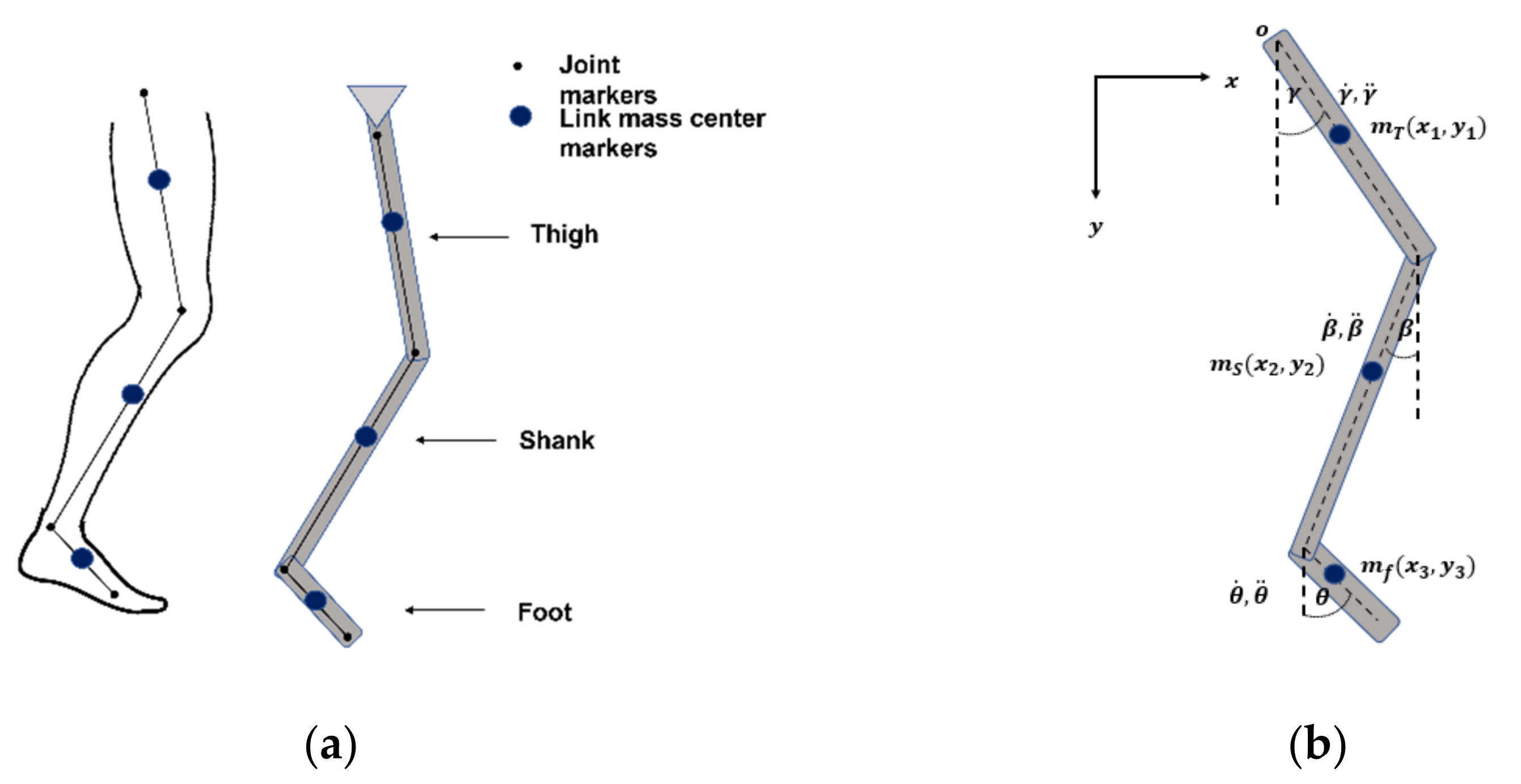
where L represents the differences in the kinetic and potential energies in the system with respect to the generalized velocities q ˙ i , and displacements q i for i variables in the system. The thigh, shank, and foot were modeled as three hinged rods at each respective joint, as seen in Figure 3a.
The three degrees of freedom (DOF) model can be seen in Figure 3b, with the origin at the top of the model, fixed to the upper body, wherein the motion for the upper body is considered negligible for the gait cycle. Translation and rotation are considered in the kinetic energies of the system with gravitational potential energy, and are converted to the generalized coordinates γ, β, θ, representing the angular displacements of the hip, knee, and ankle, respectively. The resulting equations of motion are given in Equations (2)–(4), where the angular accelerations of the hip, knee, and ankle are represented by γ ¨ ,   β ¨ ,   and   θ ¨ , respectively.
γ ¨ = 0.443 m s l T l S   β ¨ cos γ β β ˙ sin γ β γ ˙ β ˙ γ ˙ β ˙ sin γ β ˙ + m f l T l S β ¨ cos γ β β ˙ sin γ β γ ˙ β ˙ γ ˙ β ˙ sin γ β ˙ + 0.436 m f l T l f θ ˙ sin γ θ γ ˙ θ ˙ θ ¨ cos γ θ + γ ˙ θ ˙ sin γ θ ˙ + g l T m T + m S + m f s i n γ l T 2 0.9482 m T + m S + m f
β ¨ = 0.443 m S l T l S   γ ¨ cos γ β γ ˙ sin γ β γ ˙ β ˙ + γ ˙ β ˙ sin γ β ˙ + m f l T l S γ ¨ cos γ β γ ˙ sin γ β γ ˙ β ˙ + γ ˙ β ˙ sin γ β ˙ + 0.436   m f l S l f θ ¨ cos β θ θ ˙ sin β θ β ˙ θ ˙ + β ˙ θ ˙ ˙ ˙ sin β θ + g l S m S + m f s i n β l S 2 1.5295 m S + m f
θ ¨ = 0.436 m f l S l f   β ¨ cos β θ β ˙ sin β θ β ˙ θ ˙ + β ˙ θ ˙ sin β θ ˙ + 0.436 m f l T l f γ ˙ sin γ θ γ ˙ θ ˙ γ ¨ cos γ θ + γ ˙ θ ˙ sin γ θ ˙ + m f g l f s i n θ 0.7133 m f l f 2
The masses of each segment are represented as m T ,   m S ,   and   m f , for the thigh, shank, and foot, respectively. Additionally, the lengths for the thigh, shank, and foot are represented by l T ,   l S ,   and   l f . For more details on the derivation of the equations of motion, please see Appendix A. The masses and lengths for the thigh, shank, and foot are determined by gait kinematic variables during the gait cycle. The gait kinematic variables include the extent, speed, and direction of movement of joints or leg segments shown in Figure 3. Determining the mass moments of inertia in calculating the rotational kinematic energy, the centers of mass were determined by considering the proportional distance from the proximal joint for the right thigh, right shank, and right foot, as outlined in Table 1.

2.2. OpenSim 4.3: Gait Cycle Simulation

OpenSim was used to show the two phases of the gait cycle. As seen in Figure 4, the gait cycle is separated by the weightbearing phase in the right leg for the first 60% of the gait cycle [7], followed the non-weightbearing swing phase in the final 40%.
Four versions of the crouch gait common in sufferers of cerebral palsy [2,4,5] were compared with that of a normal gait in OpenSim 4.3, to determine if the current model of the exoskeleton could potentially offload forces and stresses in the knee to aid in non-invasive correction of the crouch gait. In this paper, OpenSim 4.3 is used to establish parameters for testing the exoskeleton design. OpenSim is an opensource biomechanical software used to model human body dynamics, which incorporates musculoskeletal systems for different segments of the human body. It comes with several preloaded models and motions, including a leg, arm, and an entire body for modeling gait.

2.3. SolidWorks: Modeling and Motion Analysis

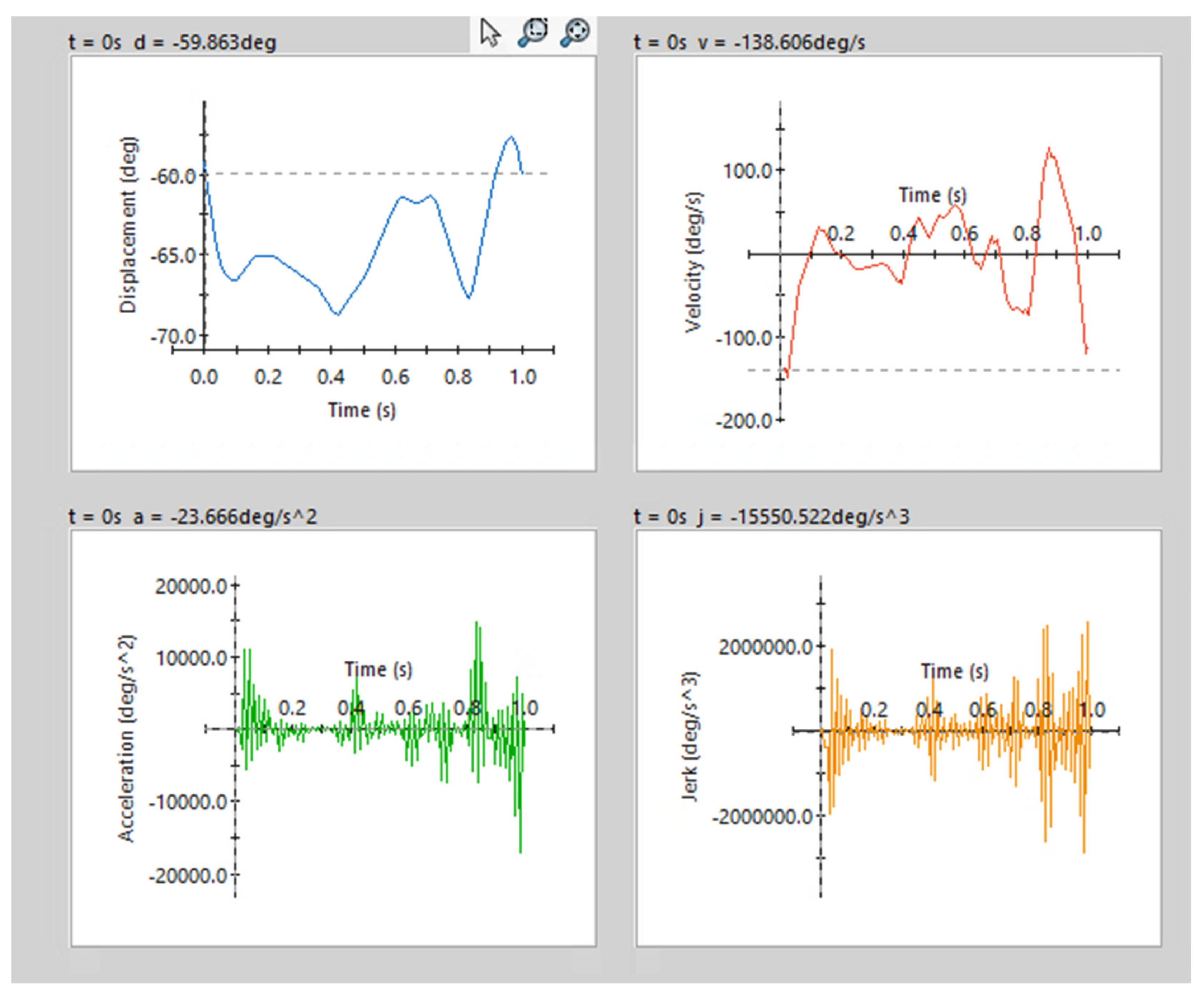
Two methods (passive only, and passive with motorized knee angle correction) were used to determine the best options for offloading forces generated in the crouch gaits. The initial conditions were taken from the data obtained from OpenSim, to determine the effectiveness of the current iterations, by conducting a dynamic force analysis in SolidWorks and comparing it to the normal gait cycle. A motor was incorporated into the design and was used to control the knee angle. The first method used data points given from the angular range of motion in the knees of each crouch gait from OpenSim that were extracted and converted to comma-separated value (CSV) files and uploaded into the function builder for the motor in SolidWorks, as indicated in Figure 5. The function builder plotted displacement, velocity, acceleration, and jerk for the exoskeleton, given the crouch gait and normal gait parameters. This was used to model the crouch gait behavior of the leg, in conjunction with the exoskeleton. The tendon forces acting in the knee for each crouch gait were plotted and extracted as CSV files, which were uploaded as force parameters to act on the exoskeleton through the gait cycle. The stiffness values for the torsion spring were adjusted to prevent extreme flexion on the knee during crouch gait. The second method motorizes the exoskeleton itself. Data points acquired from the angular range of motion for the knee of the normal gait were input into the motor, while importing data points for the tendon forces acting from the knee of the crouch gait.
The first two iterations of the knee exoskeleton involve a frame where, when paired with lightweight fabric, the thigh support rests on the posterior of the thigh, such that interference with the quadriceps is minimal, as shown in Figure 6a,b. To limit over-flexion of the knee during the stance phase, torsional springs were used in the knee joint. Flexion of the ankle occurs during flexion of the knee. By reducing the flexion of only the knee, the goal is to naturally reduce the flexion of the ankle; however, the ankle and plantar dorsiflexion have not been addressed by any iteration of the exoskeleton. The parameters for design involved finding the average circumferences for the thigh [28] and the calf, as seen in Table 2, to determine the best fit for the exoskeleton. In addition, adjustments were made to account for the incorporation of fabric, for additional comfort to the wearer.
The first iteration was designed solely to be worn around the posterior of the leg. The second iteration was designed to support the back of the thigh, with the portion below the knee to be worn around the shin. Each iteration incorporates torsional springs to inhibit flexion of the knee.
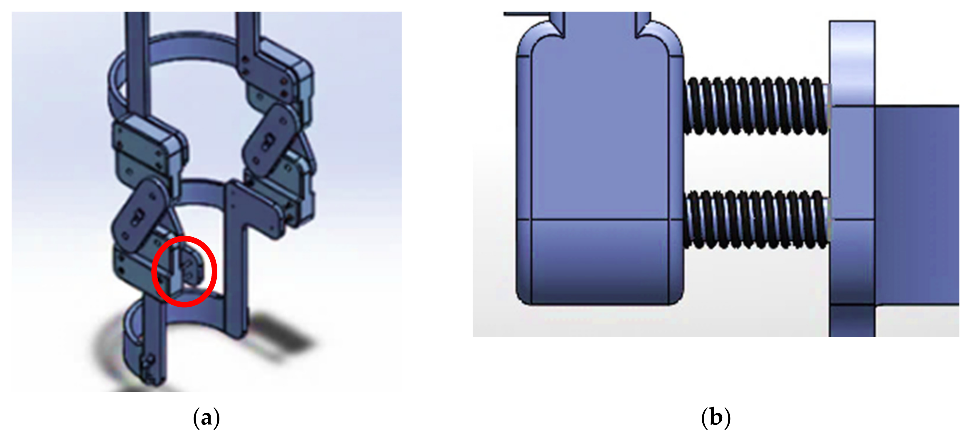
After the determination of parameters in OpenSim to be used in the spring and motor components of the exoskeleton, placements had to be determined, and the data points uploaded to SolidWorks. This process was used for both passive and motorized components of the exoskeleton. While motors were used in both, for the passive element, the motor merely simulated the knee rotation of each crouch gait. In the motorized version of the exoskeleton, the motor serves as a corrective component by increasing the range of motion through the angles of the knee in the normal gait cycle. The final design, shown in Figure 7a,b incorporates through-holes for straps to attach to the leg, as well as additional springs to adjust for differing circumferences of the leg.
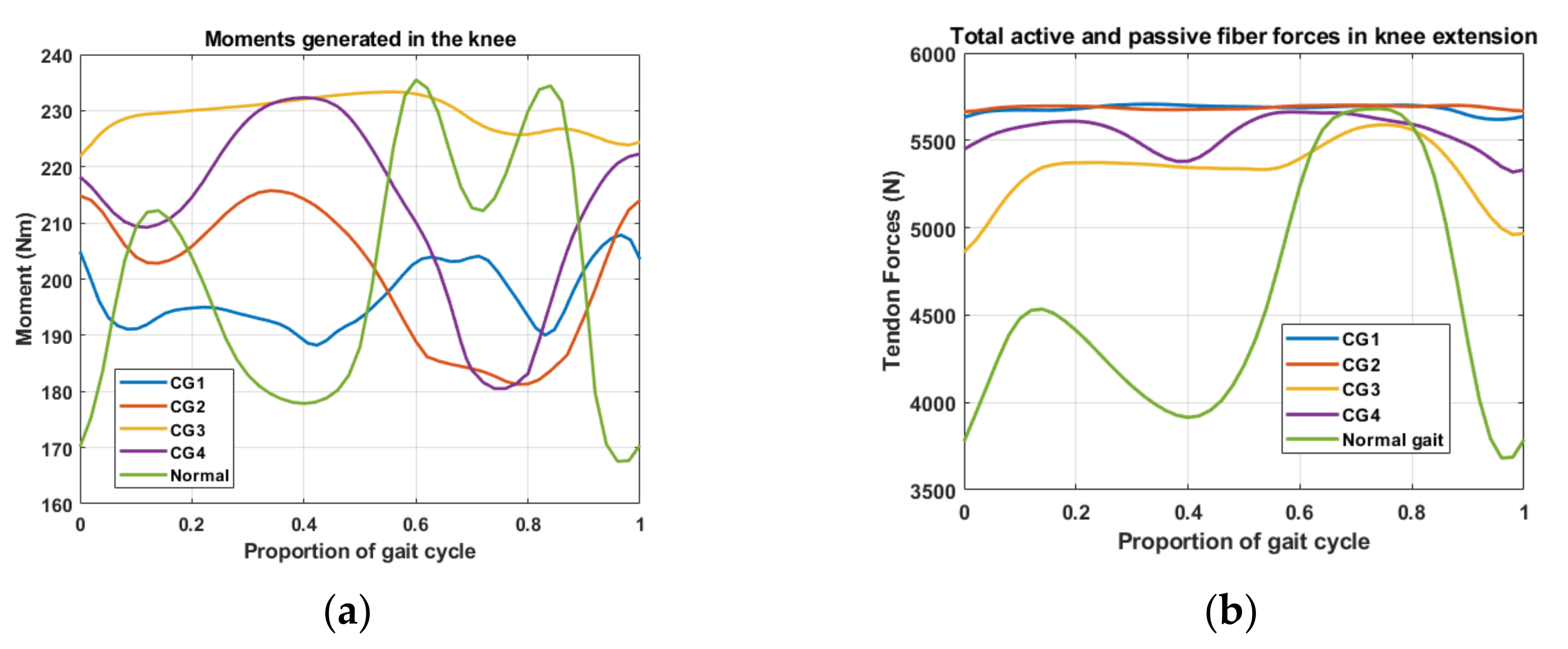
Figure 8a displays a comparison of the right knee moment produced throughout the gait cycle, by plotting the sum of the moments for the muscles involved in knee extension, including vastus intermedius, vastus lateralis, vastus medialis, and rectus femoris. The green curve shows these moments for the normal gait. The blue curve is for the first crouch gait. The orange curve represents the second crouch gait. The yellow curve represents the third crouch gait, while the purple curve represents the fourth crouch gait. Significant moments are produced, and they remain high or have limited range in crouch gaits 1 and 4, compared to that of the normal gait. Crouch gaits 2 and 3 peak in the stance phase, rather than in the swing phase of the gait cycle. They each begin with high moments compared to that of the normal gait, as a result of ankle dorsiflexion in the stance phase. Additionally, as shown in Figure 8b, the forces generated in the knee during the stance phase are significantly higher in each of the crouch gaits, compared to that of the normal gait. These forces remain high in both phases of the gait cycle.

3. Results

3.1. Passive Correction (Torsion Spring Only)

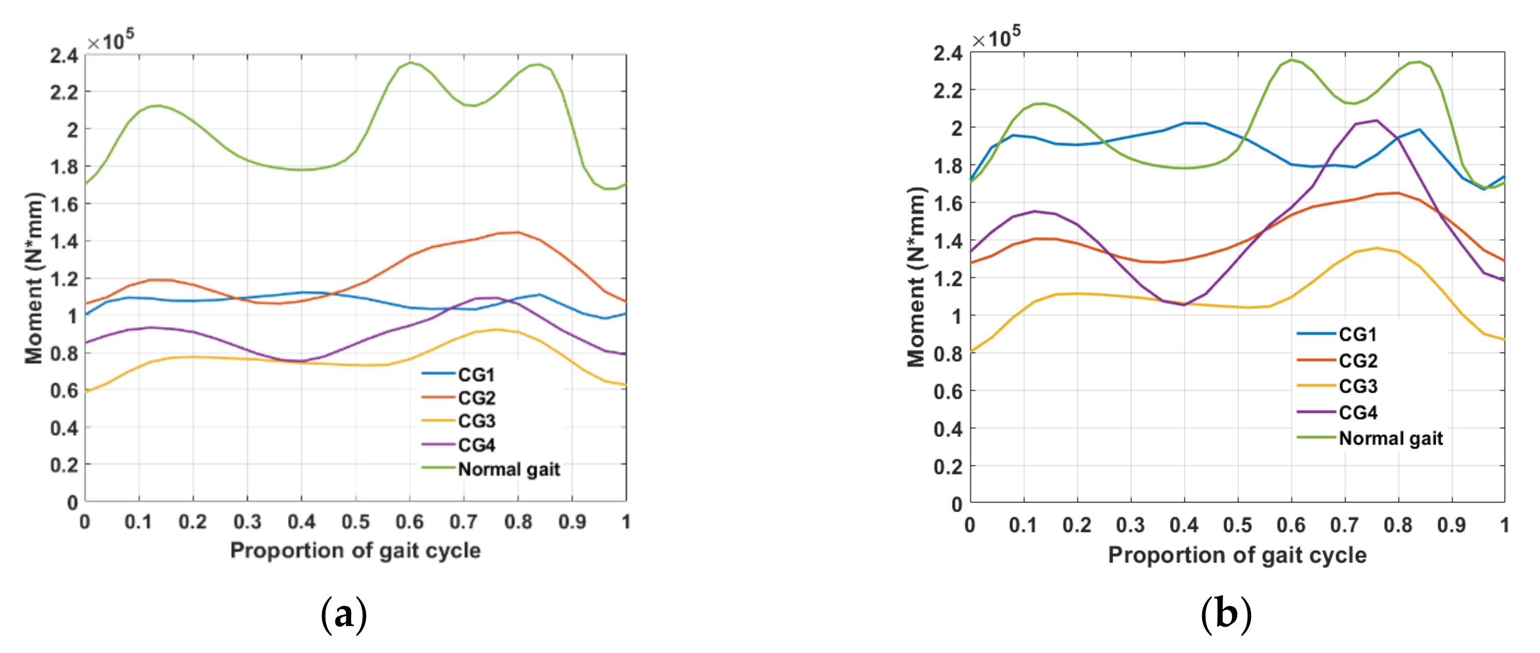
For the normal stance phase of the gait cycle, the maxima and minima occur at 14% and 40%, respectively. As seen in Figure 9a, the maximum moment generated in the stance phase is 212,194.5 Nmm, and the minimum moment generated is 177,850.8 Nmm. The incorporation of torsion springs of 20 k Nmm/deg showed an overall reduction in the moments generated across all crouch gaits. CG2 (red curve) and CG4 (purple curve) showed the greatest overall improvements in the stance phase of the gait cycle, in terms of trend. The CG2 maximum stance phase moment occurred at 12% at 118,782.2 Nmm, while the minimum occurred at 36% at 106,115.8 Nmm. The CG4 maximum stance phase moment occurred at 12% with 93,155.4 Nmm, and the minimum occurred at 40%, at 75,131.9.
Torsion springs at 30 k Nmm/deg significantly reduced moments in the stance phase in all crouch gaits except for CG 1 (blue curve) in Figure 9b. The peak moments trended toward the unimpaired (normal) gait curve in CG2 (red curve) and CG4 (purple curve). CG2 showed peak stance phase moments at 12% with 140,307.0 Nmm, and 36% at 127,834.0. The peak moments in CG4 occurred at 12% at 154,915.8 Nmm, and at 40%, at 105,117.9 Nmm. All crouch gaits, regardless of spring stiffness, require improvement in the swing phase of the gait cycle. A significant adjustment of peak moments and their occurrences in the stance phase of the gait cycle across all gaits are noticeable with both the 20 k Nmm/deg and 30 k Nmm/deg torsion springs when compared to each uncorrected crouch gait.

3.2. Passive Elements with Motorized Angular Correction

Simulating a motor with the range of motion parameters for that of the normal knee angles, torsion springs of 20 k Nmm/deg showed drastic drops in moments from the original crouch gaits. However, each crouch gait showed improvements in the graphical trend, with peak moments in the stance phase at 12%, and minima at 40%. As seen in Figure 10a, the maximum and minimum moments in CG2 (red curve) occurred at 51,730.6 Nmm and 42,701.4 Nmm, while the CG1 (blue curve) moments occurred at 51,566.5 Nmm and 42,931.9 Nmm, and the CG4 (purple curve) moments occurred at 51,238.6 Nmm and 40,5353.9 Nmm.
Results using the 30 k Nmm/deg torsions indicated further improvements in moment patterns generated in the stance phase across all CGs. Figure 10b displays the moments generated with the CG2 (red curve) peaks at 12% at 64,240.4 Nmm, while CG1 (blue curve) peaks at 12% at 64,088.1 Nmm. CG4 peaks at 12% in the gait cycle at 63,784.0 Nmm. At 40% of the gait cycle, the minimum for CG1 was 44,058.2 Nmm, CG2 was 43,828.5 Nmm, and CG 4 was 41,670.9 Nmm. All crouch gaits require improvement in the swing phase. Applying the combination of motorized components with the passive elements, a shift in moment trends occurs, which more closely aligns with those of the normal gait cycle in the stance phase.

3.3. Gap Analysis of the Data

A summary of the data is found in Table 3 and Table 4. Table 5 contains data from the normal gait cycle. The noticeable differences between the human gait simulations and the simulations conducted in SolidWorks are attributed to the physical differences between the simulations. All data was imported into SolidWorks from OpenSim. The integration of data elements between SolidWorks and OpenSim have limited the current simulation results, in that the segmental masses are not included in the SolidWorks simulations. Additionally, for the development of the exoskeleton and the performance of dynamic analyses of the exoskeleton, it was necessary to anchor the shank support to the program floor for the purposes of knee extensor force actuation. These are notable limitations between the program simulations, making true gait simulation more difficult but as accurate as possible with respect to human knee rotation. The moments generated are directly proportional to the angular accelerations and the mass moments of inertia. For the purposes of creating motion within the exoskeleton, the total fiber forces generated in the knee extension were imported into SolidWorks onto the thigh support of the device, and in the direction of the forces at t = 0. These forces were applied onto the relevant portions of the thigh support in the direction of the knee extensor force actuation. The distributed masses of the exoskeleton with respect to the axis of rotation are very small [29] when compared with the distributed masses of each moving segment on the human body. Additionally, the applied force is located on the thigh support at a close proximal distance to the mass center of the thigh. This results in a lower mass moment of inertia with the exoskeleton segments, directly impacting on the outcome of the moment generated [30] in the exoskeleton simulation, given the same range of motion of the human knee. It is expected that for the moments generated when segmental masses and fiber forces are incorporated into an integrated simulation of the leg in conjunction with the exoskeleton, the stance phase moments will increase toward that of the normal gait cycle.

4. Discussion

Crouch gaits vary widely based on the causal injury or pathology, making gait patterns difficult to define. For example, crouch gaits may be caused in individuals with cerebral palsy, which in and of itself has numerous subclassifications, depending on the area of the brain impacted, as well as how extensive the hemiplegic, paraplegic, or quadriplegic damage is. Additional causes include traumatic brain injury, stroke, and other neurological problems, as well as bone deformities. Correction may involve numerous treatment plans, including corrective orthotic devices and/or surgery. One problem with surgical treatment is that in many cases, the outcome is unknown as to whether or not the gait will improve [31]. One common surgical technique is the lengthening of hamstrings, which may improve certain aspects of gait, such as in the knee or ankle; however, surgical treatment has the potential to cause additional problems [8].
Winters et al. helped to define gait patterns in those with spastic hemiplegia that were placed into four separate groups. Comparisons with joints angles in the ankles, knees, and hips, and common symptoms, differentiated between the groups. When comparing these graphs with the knee angles produced in each crouch gait produced in OpenSim, only crouch gaits 3 and 4 contained similarities between two of the groups in Winters’ assessments. In these cases, the optimum improvement came with surgical procedures for lengthening the hamstrings. In many cases, even after surgery, the results of hamstring lengthening were inconsistent or did not work at all [14]. The incorporation of the torsional spring was able to counter the excessive flexion moments produced [32] by applying the stored energy from knee flexion to provide the necessary knee extension [33].
While these results are promising, torsion springs alone do not provide enough correction. With the passive elements alone, the reduction in moment was one component of correction; however, we saw that there needed to be a shift in the occurrence of the peak moments. There was no improvement in CG1 overall, while CG3 still had peak moments occurring at 20% and 52%. CG2 and CG4 benefitted the most from the passive elements because peak moment occurred at 12% for both CG2 and CG4, and 36% and 40%, respectively, in the gait cycle. These gaits either did not change or were near to that of the normal gait before and after motorized angular correction.
Passive components [34,35,36,37] are often used in gait rehabilitation to reduce the energy costs of task-specific [38] elements of everyday life such as walking [39], running [40], and the sit-to-stand transfer [41]. Regardless of pathology or injury, the restoration of efficient gait has been extensively researched. Often, these elements are bespoke [41] and dependent upon the affected muscle groups and joints [24,42,43]. Since gait kinematics vary with different types of crouch gaits and the source of crouch gait, it may be necessary to tailor torsion spring stiffnesses based on the individual needs of the subject and the severity of knee flexion. Common factors in crouch gait include shortened or tight hamstrings, and quadriceps weakness as a result of constant flexion in the knee throughout the stance phase of the gait cycle. Chaichaowarat et al. established that incorporating torsion springs in a knee exoskeleton in cycling helped to balance the workload between the quadriceps and the hamstrings [25,31]. The torsion spring stored energy from knee flexion to aid in knee extension, reducing effort of the quadriceps while increasing effort of the hamstrings [24,31]. Since cycling involves extreme knee flexion, it was expected that comparable results might be achieved in individuals suffering from crouch gait. As seen in the results, a motorized component is necessary to aid in crouch gait rehabilitation. Ideally, the incorporation of a lightweight, noninvasive, robotic element in knee angle correction is advisable. This work is an incremental step in crouch gait correction in the stance phase. As such, we seek to address the swing phase in crouch gait, as well as advancements in robotic elements of the knee exoskeleton.

5. Conclusions

The gait cycle is composed of two major phases; the stance phase and the swing phase, with subphases defined within each. The stance phase comprises 60% of the gait cycle, while the swing phase comprises the final 40% of the gait cycle. The crouch gait is defined by excessive flexion of the knee during the stance phase of the gait cycle. Factors affecting crouch gait are numerous, but they are seen especially in those with cerebral palsy. Excessive flexion in the knee results in the degradation of joints and mobility over time, resulting in a complete loss of ambulation if left untreated. Exoskeletons for rehabilitative purposes are common for many such injuries and complications of the leg. While many exoskeletons are motorized for assistive mobility, the incorporation of passive elements was sought, to reduce the cost of the exoskeleton. Most exoskeletons are designed to be worn on the lower extremity, to correct ankle and hip rotation.
SolidWorks was used to model a lower limb exoskeleton to counter the reaction forces produced in the knee for four different types of crouch gait. The exoskeleton was modeled using the average circumferences for the thigh and shank and was modeled using passive elements to reduce cost and to reduce invasiveness, to keep the exoskeleton lightweight. Since ankle flexion is more pronounced during knee flexion, the team sought to explore the implications of the device for use solely on the knee. Torsional springs were incorporated to inhibit the overflexion of the knee during the stance phase of the gait cycle. Dampers were included, to reduce the recovery force of the spring entering the swing phase of the gait, to prevent a forced overextension of the knee.
To establish the parameters for testing the exoskeleton, OpenSim 4.3 was used. The angles of rotation during the gait cycle were plotted for four different crouch gaits and compared to the normal gait. Excessive forces, as well as moments, are produced in the knee because of excessive flexion during the stance phase of the gait cycle. The data points from the forces and moments were exported as CSV files and applied to the exoskeleton, first incorporating only passive elements through the use of torsional springs while simulating the knee rotation of the four crouch gaits.
The gait cycle was set to 1s, to analyze the proportion of the gait cycle, in SolidWorks. Results from the passive elements indicated the greatest improvements with both 20 k Nmm/deg and 30 k Nmm/deg in CG2 and CG4. The 30 k Nmm/deg torsion spring simulations showed little to no improvement in CG1. The 30 k Nmm/deg torsion springs showed the greatest overall trend toward the normal gait, while the 20 k Nmm torsion springs showed minor improvements over all crouch gaits, except for CG1 in the stance phase. The swing phase requires further improvement in all crouch gaits.
In the second round of testing, a motor was incorporated to drive the exoskeleton using the normal range of motion of the knee, while simulating forces on the exoskeleton from each crouch gait. All results showed the same trends as the normal knee angular displacement; however, using different spring stiffnesses resulted only in a change of magnitude of the moments generated. Thus, it was determined that the best results would involve the incorporation of both passive and motorized elements while driving the exoskeleton, using the normal range of motion in the knee for both angular and moment correction in the crouch gait.

6. Future Work

While the results for stance phase correction are promising, it is necessary to address the swing phase of the gait cycle, as well as to integrate passive and motorized correction to ensure a smooth transition from the stance phase to the swing phase. Future work involves the development of a multi-functional, multipurpose robotic exoskeleton to address crouch gait problems that occur throughout the lower limbs, including the hips and ankles.

Author Contributions

Conceptualization, K.B.B. and H.H.; data curation, K.B.B. and H.H.; formal analysis, K.B.B.; investigation, K.B.B. and H.H.; methodology, K.B.B. and H.H.; project administration, C.-H.G.; resources, C.-H.G. and A.I.; software, K.B.B. and H.H.; supervision, C.-H.G. and A.I.; validation, C.-H.G. and A.I.; writing—original draft preparation, K.B.B.; writing—review and editing, C.-H.G. and A.I. All authors have read and agreed to the published version of the manuscript.

Funding

This research received no external funding.

Institutional Review Board Statement

Not applicable.

Informed Consent Statement

Not applicable.

Data Availability Statement

Not applicable.

Acknowledgments

The authors would like to express their special thanks to Joni Hill and Carlos Ramirez-Ortiz for their insightful comments and discussions.

Conflicts of Interest

The authors declare no conflict of interest.

Appendix A

The derivations for the governing equations are as follows:
Position:
x 1 = 0.430 l T s i n γ
x 2 = l T s i n γ 0.443 l S s i n β
x 3 = l T s i n γ l S s i n β + 0.436 l f s i n θ
y 1 = 0.430 l T c o s γ
y 2 = l T c o s γ + 0.443 l S c o s β
y 3 = l T c o s γ + l S c o s β + 0.436 l f c o s θ
Velocity:
x 1 ˙ = 0.430 γ ˙ l T c o s γ
x 2 ˙ = γ ˙ l T c o s γ 0.443 β ˙ l S c o s β
x 3 ˙ = γ ˙ l T c o s γ β ˙ l S c o s β + 0.436 θ ˙ l f c o s θ
y 1 ˙ = 0.430 γ ˙ l T s i n γ
y 2 ˙ = γ ˙ l T s i n γ + 0.443 β ˙ l S s i n β
x 3 ˙ = γ ˙ l T s i n γ + β ˙ l S s i n β 0.436 θ ˙ l f s i n θ
L = T V
where T is the total translational and rotational energy in the system, and V is the total potential energy in the system.
T = 1 2 m i x ˙ i + y ˙ i 2 + 1 2 I α ˙ 2
where α is used generally to represent the angular velocities of each segment.
I 0 = I s e g m e n t + m i r 2
where r is the distance from the proximal joint to the center of mass for each segment. After appropriate substitutions with generalized coordinates and trigonometric identities, the total translational kinetic energy is:
T 1 k = 0.09245 m T l T 2 γ 2
T 2 k = 1 2 m S γ ˙ 2 l T 2 + β ˙ 2 l S 2 0.886 γ ˙ β ˙ l T l S cos γ β
T 3 k = 1 2 m f γ ˙ 2 l T 2 + β ˙ 2 l S 2 + 0.190 θ ˙ 2 l f 2 2 γ ˙ β ˙ l T l S cos γ β + 0.872 γ ˙ θ ˙ l T l f cos γ θ 0.872 θ ˙ β ˙ l S l f cos β θ
The total rotational energy becomes:
T 1 r = 1 6 γ ˙ m T l T 2 + 1 2 γ ˙ 2 m T 0.430 l T 2
T 2 r = 1 6 β ˙ m S l S 2 + 1 2 β ˙ 2 m S 0.433 l S 2
T 1 r = 1 6 θ ˙ m f l f 2 + 1 2 θ ˙ 2 m f 0.436 l f 2
The constants to be squared are the relative distances from the proximal joint to the center of mass.
The potential energy in the system is the gravitational potential energy; thus:
V 1 = m T g l T cos γ
V 2 = m S g l T cos γ + l S c o s β
V 3 = m f g l T cos γ + l S c o s β + l f c o s θ
The Langrangian must be solved for each variable in the system to determine the governing equations.
d d t T γ ˙ = T γ V γ
d d t T β ˙ = T β V β
d d t T θ ˙ = T θ V θ

References

  1. Delp, S.L.; Arnold, A.S.; Piazza, S.J. Graphics-based modeling and analysis of gait abnormalities. Biomed. Mater. Eng. 1998, 8, 227–240. [Google Scholar] [PubMed]
  2. Steele, K.M.; DeMers, M.S.; Schwartz, M.H.; Delp, S.L. Compressive tibiofemoral force during crouch gait. Gait Posture 2012, 35, 556–560. [Google Scholar] [CrossRef] [PubMed] [Green Version]
  3. Steele, K.M.; van der Krogt, M.M.; Schwartz, M.H.; Delp, S.L. How much muscle strength is required to walk in a crouch gait? J. Biomech. 2012, 45, 2564–2569. [Google Scholar] [CrossRef] [PubMed] [Green Version]
  4. Lerner, Z.F.; Damiano, D.L.; Bulea, T.C. A robotic exoskeleton to treat crouch gait from cerebral palsy: Initial kinematic and neuromuscular evaluation. In Proceedings of the 2016 38th Annual International Conference of the IEEE Engineering in Medicine and Biology Society (EMBC), Orlando, FL, USA, 16–20 August 2016; IEEE: Washington, DC, USA, 2016; pp. 2214–2217. [Google Scholar]
  5. Ganjwala, D.; Shah, H. Management of the knee problems in spastic cerebral palsy. Indian J. Orthop. 2019, 53, 53–62. [Google Scholar] [CrossRef]
  6. Hilberink, S.R.; Roebroeck, M.E.; Nieuwstraten, W.; Jalink, L.; Verheijden, J.; Stam, H.J. Health issues in young adults with cerebral palsy: Towards a life-span perspective. J. Rehabil. Med. 2007, 39, 605–611. [Google Scholar] [CrossRef] [Green Version]
  7. Shah, K.; Solan, M.; Dawe, E. The gait cycle and its variations with disease and injury. Orthop. Trauma 2020, 34, 153–160. [Google Scholar] [CrossRef]
  8. Arnold, A.S.; Liu, M.Q.; Schwartz, M.H.; Ounpuu, S.; Delp, S.L. The role of estimating muscle-tendon lengths and velocities of the hamstrings in the evaluation and treatment of crouch gait. Gait Posture 2006, 23, 273–281. [Google Scholar] [CrossRef]
  9. Rose, J.; Gamble, J.G.; Medeiros, J.; Burgos, A.; Haskell, W.L. Energy cost of walking in normal children and in those with cerebral palsy: Comparison of heart rate and oxygen uptake. J. Pediatr. Orthop. 1989, 9, 276–279. [Google Scholar] [CrossRef]
  10. Waters, R.L.; Mulroy, S. The energy expenditure of normal and pathologic gait. Gait Posture 1999, 9, 207–231. [Google Scholar] [CrossRef]
  11. Jahnsen, R.; Villien, L.; Aamodt, G.; Stanghelle, J.; Holm, I. Musculoskeletal pain in adults with cerebral palsy compared with the general population. J. Rehabil. Med. 2004, 36, 78–84. [Google Scholar] [CrossRef] [Green Version]
  12. Bottos, M.; Gericke, C. Ambulatory capacity in cerebral palsy: Prognostic criteria and consequences for intervention. Dev. Med. Child Neurol. 2003, 45, 786–790. [Google Scholar] [CrossRef] [PubMed]
  13. Brandon, S.C.; Thelen, D.G.; Smith, C.R.; Novacheck, T.F.; Schwartz, M.H.; Lenhart, R.L. The coupled effects of crouch gait and patella alta on tibiofemoral and patellofemoral cartilage loading in children. Gait Posture 2018, 60, 181–187. [Google Scholar] [CrossRef] [PubMed]
  14. Park, H.; Park, B.K.; Park, K.B.; Abdel-Baki, S.W.; Rhee, I.; Kim, C.W.; Kim, H.W. Distal femoral shortening osteotomy for severe knee flexion contracture and crouch gait in cerebral palsy. J. Clin. Med. 2019, 8, 1354. [Google Scholar] [CrossRef] [PubMed] [Green Version]
  15. Pelrine, E.R.; Novacheck, T.F.; Boyer, E.R. Knee pain and crouch gait in individuals with cerebral palsy: What impact does crouch-related surgery have? Dev. Med. Child Neurol. 2020, 62, 709–713. [Google Scholar] [CrossRef] [PubMed]
  16. Graham, H.K.; Selber, P. Musculoskeletal aspects of cerebral palsy. J. Bone Jt. Surg. Br. Vol. 2003, 85, 157–166. [Google Scholar] [CrossRef] [PubMed]
  17. Mullaji, A.; Shetty, G.M. Persistent hindfoot valgus causes lateral deviation of weightbearing axis after total knee arthroplasty. Clin. Orthop. Relat. Res. 2011, 469, 1154–1160. [Google Scholar] [CrossRef] [Green Version]
  18. Patthanacharoenphon, C.; Maples, D.L.; Saad, C.; Forness, M.J.; Halanski, M.A. The effects of patellar tendon advancement on the immature proximal tibia. J. Child. Orthop. 2013, 7, 139–146. [Google Scholar] [CrossRef] [Green Version]
  19. Li, G.; DeFrate, L.; Zayontz, S.; Park, S.; Gill, T. The effect of tibiofemoral joint kinematics on patellofemoral contact pressures under simulated muscle loads. J. Orthop. Res. 2004, 22, 801–806. [Google Scholar] [CrossRef]
  20. Classification of Gait Patterns in Cerebral Palsy. Physiopedia. 13 September 2019. Available online: https://www.physio-pedia.com/index.php?title=Classification_of_Gait_Patterns_in_Cerebral_Palsy&oldid=222810 (accessed on 29 November 2021).
  21. Bregman, D.J.; Van der Krogt, M.; De Groot, V.; Harlaar, J.; Wisse, M.; Collins, S. The effect of ankle foot orthosis stiffness on the energy cost of walking: A simulation study. Clin. Biomech. 2011, 26, 955–961. [Google Scholar] [CrossRef] [Green Version]
  22. Kerkum, Y.L.; Buizer, A.I.; Van Den Noort, J.C.; Becher, J.G.; Harlaar, J.; Brehm, M.A. The effects of varying ankle foot orthosis stiffness on gait in children with spastic cerebral palsy who walk with excessive knee flexion. PLoS ONE 2015, 10, e0142878. [Google Scholar] [CrossRef] [Green Version]
  23. Damiano, D.L.; Arnold, A.S.; Steele, K.M.; Delp, S.L. Can strength training predictably improve gait kinematics? a pilot study on the effects of hip and knee extensor strengthening on lower-extremity alignment in cerebral palsy. Phys. Ther. 2010, 90, 269–279. [Google Scholar] [CrossRef] [PubMed] [Green Version]
  24. Collins, S.H.; Wiggin, M.B.; Sawicki, G.S. Reducing the energy cost of human walking using an unpowered exoskeleton. Nature 2015, 522, 212–215. [Google Scholar] [CrossRef] [PubMed] [Green Version]
  25. Naf, M.B.; Junius, K.; Rossini, M.; Rodriguez-Guerrero, C.; Vanderborght, B.; Lefeber, D. Misalignment compensation for full human-exoskeleton kinematic compatibility: State of the art and evaluation. Appl. Mech. Rev. 2018, 70, 050802. [Google Scholar] [CrossRef] [Green Version]
  26. Scherer, M.J. Outcomes of Assistive Technology Use on Quality of Life. Disabil. Rehabil. 1996, 18, 439–448. [Google Scholar] [CrossRef] [PubMed]
  27. Jung, K.J.; Kimm, H.; Yun, J.E.; Jee, S.H. Thigh circumference and diabetes: Obesity as a potential effect modifier. J. Epidemiol. 2013, 23, 329–336. [Google Scholar] [CrossRef] [Green Version]
  28. Hicks, J.L.; Delp, S.L.; Schwartz, M.H. Can biomechanical variables predict improvement in crouch gait? Gait Posture 2011, 34, 197–201. [Google Scholar] [CrossRef] [PubMed] [Green Version]
  29. Royer, T.D.; Martin, P.E. Manipulations of leg mass and moment of inertia: Effects on energy cost of walking. Med. Sci. Sports Exer. 2005, 37, 649–656. [Google Scholar] [CrossRef]
  30. Browning, R.C.; Modica, J.R.; Kram, R.; Goswami, A. The effects of adding mass to the legs on the energetics and biomechanics of walking. Med. Sci. Sports Exerc. 2007, 39, 515–525. [Google Scholar] [CrossRef] [Green Version]
  31. Chaichaowarat, R.; Granados, D.F.P.; Kinugawa, J.; Kosuge, K. Passive knee exoskeleton using torsion spring for cycling assistance. In Proceedings of the 2017 IEEE/RSJ International Conference on Intelligent Robots and Systems (IROS), Vancouver, BC, Canada, 24–28 September 2017; IEEE: Washington, DC, USA, 2017; pp. 3069–3074. [Google Scholar]
  32. Spring, A.N.; Kofman, J.; Lemaire, E.D. Design and evaluation of an orthotic knee-extension assist. IEEE Trans. Neural Syst. Rehabil. Eng. 2012, 20, 678–687. [Google Scholar] [CrossRef]
  33. Winters, T.F.; Gage, J.R.; Hicks, R. Gait patterns in spastic hemiplegia in children and young adults. J. Bone Jt. Surg. Am. 1987, 69, 437–441. [Google Scholar]
  34. Rome, L.C.; Flynn, L.; Yoo, T.D. Rubber bands reduce the cost of carrying loads. Nature 2006, 444, 1023–1024. [Google Scholar] [CrossRef] [PubMed]
  35. Lee, H.; Kim, S.H.; Park, H.S. A fully soft and passive assistive device to lower the metabolic cost of sit-to-stand. Front. Bioeng. Biotechnol. 2020, 8, 966. [Google Scholar] [CrossRef] [PubMed]
  36. Van Dijk, W.; Van der Kooij, H.; Hekman, E. A Passive Exoskeleton with Artificial Tendons: Design and Experimental Evaluation. In Proceedings of the IEEE International Conference on Rehabilitation Robotics, Zurich, Switzerland, 29 June–1 July 2011; pp. 1–6. [Google Scholar]
  37. Panizzolo, F.A.; Bolgiani, C.; Di Liddo, L.; Annese, E.; Marcolin, G. Reducing the energy cost of walking in older adults using a passive hip flexion device. J. Neuroeng. Rehab. 2019, 16, 117. [Google Scholar] [CrossRef] [PubMed] [Green Version]
  38. Sasaki, K.; Neptune, R.R. Differences in muscle function during walking and running at the same speed. J. Biomech. 2006, 39, 2005–2013. [Google Scholar] [CrossRef]
  39. Haufe, F.L.; Wolf, P.; Riener, R.; Grimmer, M. Biomechanical effects of passive hip springs during walking. J. Biomech. 2020, 98, 1–9. [Google Scholar] [CrossRef] [PubMed]
  40. Nasiri, R.; Ahmadi, A.; Ahmadabadi, M.N. Reducing the energy cost of human running using an unpowered exoskeleton. IEEE Trans. Neural Syst. Rehab. Eng. 2018, 26, 2026–2032. [Google Scholar] [CrossRef]
  41. Lovrenovic, Z.; Doumit, M. Development and testing of a passive walking assist exoskeleton. Biocybern. Biomed. Eng. 2019, 39, 992–1004. [Google Scholar] [CrossRef]
  42. Wang, Y.; Zhao, G.; Diao, Y.; Feng, Y.U.; Li, G. Performance analysis of unpowered lower limb exoskeleton during sit down and stand up. Robotica 2022, 40, 1274–1292. [Google Scholar] [CrossRef]
  43. Lee, K.M.; Wang, D. Design analysis of a passive weight support lower-extremity-exoskeleton with compliant knee joint. In Proceedings of the 2015 IEEE International Conference on Robotics and Automation (ICRA), Seattle, WA, USA, USA, 26–30 May 2015; pp. 5572–5577. [Google Scholar]
Figure 1. Normal knee angle (red curve) by phase of gait cycle with respect to proportion of gait cycle. The black arrows represent the duration of the stance phase from 0.0 to 0.6 proportion of the gait cycle, and the swing phase from 0.6 to 1.0 of the gait cycle.
Applsci 12 07034 g001
Figure 2. Schematic for overall process of exoskeleton design.
Applsci 12 07034 g002
Figure 3. Figures for representation of (a) links, joints, and centers of mass for the leg segments and (b) corresponding free body diagram.
Applsci 12 07034 g003
Figure 4. An OpenSim generated diagram for the stance and swing phase of the gait cycle.
Applsci 12 07034 g004
Figure 5. SolidWorks function builder used for angular displacement of the knee for crouch gait 1.
Applsci 12 07034 g005
Figure 6. Two iterations of the passive exoskeleton where the thigh support should sit behind the thigh, and (a) shank support is worn in front of the leg, (b) shank support is worn behind the leg.
Applsci 12 07034 g006
Figure 7. The final design of the exoskeleton (a) in its entirety and (b) a close up of the adjustable mechanism for leg circumference.
Applsci 12 07034 g007
Figure 8. Graphs of (a) the moments generated in the knee throughout the gait cycle; (b) total active and passive fiber forces generated in the knee extensors.
Applsci 12 07034 g008
Figure 9. Graphs of the moments generated in the knee throughout the gait cycle, using: (a) 20 k Nmm/deg torsion springs and (b) 30 k Nmm/deg torsion springs.
Applsci 12 07034 g009
Figure 10. Graphs of passive elements with motorized angular knee correction using (a) 20 k Nmm/deg torsion springs and (b) 30 k Nmm/deg torsion springs.
Applsci 12 07034 g010
Table 1. Parameters for proportional distance from the proximal joint to the segmental mass center.
SegmentProximal Joint to Mass Center
Thigh0.430
Shank0.443
Foot0.436
Table 2. Design parameters used to determine dimensions of wearable exoskeleton.
SegmentCircumference (cm)
Thigh39.5
Shank52.0
Table 3. Moment maxima taken from simulations for each crouch gait.
Maximum MomentsTorsion Springs 20 k Nmm/Deg%Gait
Cycle
Motorized Correction 20 k Nmm/Deg%Gait
Cycle
Torsion Springs 30 k Nmm/Deg%Gait
Cycle
Motorized Correction 30 k Nmm/Deg%Gait
Cycle
CG1112,117.54051,566.512201,854.66064,088.112
CG2118,782.21251,730.612140,307.01264,240.412
CG377,376.42049,834.212111,187.32062,483.812
CG493,155.361251,238.612154,915.81263,784.012
Table 4. Moment minima taken from simulations for each crouch gait.
Minimum MomentsTorsion Springs 20 k Nmm/Deg%Gait
Cycle
Motorized Correction 20 k Nmm/Deg%Gait
Cycle
Torsion Springs 30 k Nmm/Deg%Gait
Cycle
Motorized Correction 30 k Nmm/Deg%Gait
Cycle
CG1103,800.86042,931.940179,830.66044,058.240
CG2106,115.83642,701.440127,8343643,828.540
CG372,958.895240,303.240103,772.25241,439.140
CG475,131.994040,535.9240105,117.94041,670.940
Table 5. Moment maximum, minimum, and their corresponding percentage occurrences within the normal gait cycle.
Normal GaitMaximum Moment%Gait CycleMinimum Moment%Gait Cycle
212,194.514177,850.840
Publisher’s Note: MDPI stays neutral with regard to jurisdictional claims in published maps and institutional affiliations.