Article

Optical Fiber Sensor with Stable Operating Point for AC Magnetic Field Measurement

1
South China Academy of Advanced Optoelectronics, South China Normal University, Guangzhou 510006, China
2
Ningbo Research Institute, Zhejiang University, Ningbo 315100, China
3
Centre for Optical and Electromagnetic Research, Zhejiang Provincial Key Laboratory for Sensing Technologies, State Key Laboratory of Modern Optical Instrumentation, Zhejiang University, Hangzhou 310058, China
*
Authors to whom correspondence should be addressed.
Appl. Sci. 2022, 12(14), 7049; https://doi.org/10.3390/app12147049
Submission received: 25 May 2022 / Revised: 6 July 2022 / Accepted: 11 July 2022 / Published: 12 July 2022
(This article belongs to the Section Optics and Lasers)

Abstract

:
A novel alternating current (AC) magnetic field sensor that has a stable operating point and is insensitive to ambient temperature fluctuations is presented. The sensor is based on a high attenuation fiber Bragg grating (HAFBG) attached to a magnetostrictive rod. A stable operating point is achieved by regulating a heating laser based on a feedback algorithm that compensates the temperature fluctuations of the surrounding environment. Experimental results show that the sensor responds well to dynamic magnetic fields and is able to ensure a stable operating point in the range of at least 15 °C in an ambient temperature disturbance test. The ease of fabrication and excellent performance suggest that the proposed fiber sensor is suitable for practical AC magnetic field sensing applications, such as health monitoring of transformers and fault diagnosis of induction motors.

1. Introduction

Magnetic field sensors are playing an increasingly important role in several fields, such as navigation, geophysics, aerospace engineering, the power industry, and biomedical research [1,2,3,4]. Common magnetic field sensors based on, e.g., the Hall effect [5], anisotropic magnetoresistance [6], or superconducting quantum interference [7], have disadvantages such as large size, complicated system design and operation, as well as high costs, all of which are detrimental for their use in practical applications. In addition, their inherent electromagnetic sensitivity makes them unusable in certain environments, such as oil and gas pipelines.
Compared with electric and magnetic sensing technologies, optical sensors offer many advantages, including small size, robustness to harsh environments, long-distance sensing ability, and immunity to electromagnetic interference, which have prompted a rapid development of optical fiber sensing technology. However, an optical fiber is in itself not sensitive to an electromagnetic field, and thus developing an optical fiber-based magnetic field sensor will largely depend on the sensing characteristics of added magnetic induction materials. Magnetic induction materials can be classified into three categories according to their working principles: magnetic fluid [8,9,10,11,12], magnetostrictive materials [2,3,13,14,15,16,17,18,19,20], and magneto-rotational materials [21,22,23,24]. A magnetic fluid can flexibly be integrated into many types of fiber sensing structures, such as fiber Fabry–Perot interferometers [25,26], fiber Mach–Zehnder interferometers [27], fiber Bragg gratings (FBG) [12], and fiber tapering structures [28]. However, light absorption by a magnetic fluid always introduces large transmission losses. Magnetostrictive materials, in the shape of particles, rods, or films, convert magnetic field changes into elongation changes through the magnetostrictive effect that can, e.g., be utilized to alter the period of an FBG or the length of a Fabry–Perot cavity, resulting in spectral wavelength shifts useable for sensing. This can, for example, be utilized by depositing a magnetostrictive thin film on the surface of FBG [14,17] to encapsulate an FBG directly on magnetostrictive rods [29] or in a mixture of magnetostrictive particles and epoxy resin [30]. Magnetic sensing based on the Faraday rotation effect has high sensitivity but requires a complex and expensive demodulation system.
A major challenge facing most optical fiber magnetic field sensors proposed to date is how to effectively reduce temperature crosstalk. Temperature crosstalk elimination can be achieved by different technologies, which the following are examples of. In 2022, Zhang et al. proposed a composite magnetic fiber sensor based on an MF-coated nonadiabatic tapered microfiber cascaded with an FBG, and a sensitivity matrix was used to overcome the temperature crosstalk [28]. This kind of sensor requires the use of additional fiber gratings or other structures that can act as a temperature reference. Yoffe et al. [31] introduced a passive temperature-compensating package to reduce temperature sensitivity by using a passive mount composed of two materials with different thermal expansion coefficients. However, sensors of this kind are either extremely complex in structure or require the use of additional special devices. Liu et al. proposed a quadrature phase-stabilized three-wavelength demodulation technique to avoid imbalances and disturbances between three optical paths [32]. Sensors of this type, however, require either an additional temperature sensor head, temperature-compensating materials, or additional laser sources, greatly increasing cost, size, and complexity.
Aiming to resolve the challenge of temperature crosstalk, we propose in this work a high attenuation fiber Bragg grating (HAFBG), which can realize an alternating current (AC) magnetic field measurement with a stable operating point using a magnetic field demodulation algorithm. The sensor consists of a HAFBG and a magnetostrictive rod with a square cross-section. The calibration results show that the sensitivities of temperature, heating laser power, and magnetic field intensity are 7.86 pm/°C, 0.604 nm/W, and 3.95 pm/mT, respectively. An applied AC magnetic field will dynamically alter the FBG period, resulting in Bragg wavelength shifts of the reflection spectrum. A stable operating point is achieved by adjusting the power of a heating laser that emits 980 nm light. Experimental results show that the sensor can maintain a stable operating point when the ambient temperature is varied in a 15 °C range. Because of its small size, simple fabrication, convenient and stable operation, the proposed sensor has great potential for practical AC magnetic field sensing applications, such as health monitoring of transformers and fault diagnosis of induction motors.
It is instructive to compare the sensor presented here with other representative magnetic field sensors based on FBG. Comparisons of sensing structure, effective sensing length, sensitivity, and temperature compensation method are listed in Table 1. For magnetic fluid-based FBG magnetic sensors, the fiber cladding should be etched to enhance the sensitivity, which makes the fiber fragile and increases the transmission loss [12]. The FBG coated with magnetostrictive thin film can realize compact size but has low sensitivity [14]. For magnetostrictive material-based FBG magnetic sensors, FBGs always bond to the magnetostrictive material surface or are embedded in the magnetostrictive material. In 2000, a standard FBG was bonded onto a Terfenol–D alloy surface, achieving a sensitivity of about 8.6 pm/mT for an effective sensing length of 25 mm [33]. FBGs embedded in a magnetostrictive polymer composite have the advantage of flexible sensor shape but at the expense of weak thermostability and low sensitivity [20]. In 2022, a new FBG encapsulation structure was designed to enhance sensor sensitivity based on a magnetostrictive polymer composite. However, the total encapsulation size increased accordingly, and the fabrication process is relatively complex [30]. For more conventional temperature compensation approaches, an extra temperature sensor head is required, which greatly increases the size of the sensor [14,20,33]. In contrast, the sensor proposed in this work can realize relatively high sensitivity with a short effective sensing, while it also eliminates temperature crosstalk through the photo-thermal effect of HAF instead of a separate temperature sensor.

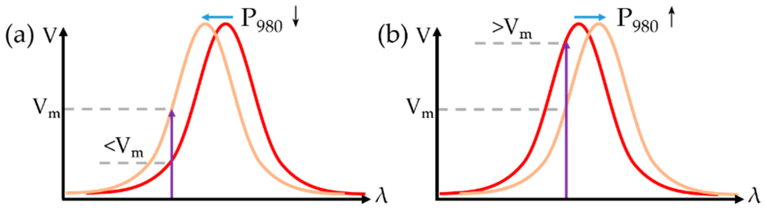
2. Theoretical Analysis

The proposed sensor is based on a fiber Bragg grating (FBG) fabricated on the core of a high attenuation fiber (HAF) that is bonded onto a magnetostrictive rod surface. The HAF has a high concentration of doping that can be efficiently heated by absorbing energy from a heating laser, an effect that can be utilized to mitigate effects of shifts in the ambient temperature and thus realize a stable operating point. The heat generated by absorbing power from the heating laser predominately affects the effective refractive index of the HAF core—that is, it affects the resonant Bragg wavelength of FBG. The Bragg wavelength λB, at which light traveling through the HAF Bragg grating (HAFBG) will be reflected, is defined as:
λ B = 2 n eff Λ ,
where neff is the effective refractive index of the core of the HAF and Λ is the period of the refractive index modulation of the HAFBG. When an external magnetic field acts on the sensor, the length of magnetostrictive rod will change due to the magnetostriction effect. The strain of the magnetostrictive rod is related to the magnetic field as [34]:
ε = Δ L L = C f B 2 ,
where ε is the strain of magnetostrictive rod, and ΔL and L are the elongation length and original length of the magnetostrictive rod, respectively. Cf is a coefficient related to the magnetostriction effect, which is linearly dependent on the magnetic field intensity B within a specific magnetic field range. B can be expressed as:
B = B 0 + A cos ( ω B t ) ,
where B0 is the DC offset, and A and ωB are the amplitude and angular frequency of the applied magnetic field, respectively. When the magnetostrictive rod is strained, the HAFBG to which it is attached will also experience a strain ε, inducing changes in neff and Λ that result in a wavelength drift of λB. The wavelength drift of λB is also influenced by the changes in the ambient temperature and can thus be described as:
Δ λ B = λ B ε ε + λ B T T ,
where ΔλB is the offset value of the wavelength drift of λB and T the ambient temperature. The theoretical sensitivity of λB related to B (based on the strain of the magnetostrictive rod) is given as [13]:
S B = λ B B = 2 B C f λ B { 1 n e f f 2 2 [ p 12 v ( p 11 + p 12 ) ] } ,
where SB is the sensitivity, p11 and p12 are the coefficients of the strain optic tensor, and ν is the Poisson ratio. The theoretical sensitivity of the λB related to T is given as [35]:
S T = λ B T = λ B ( α Λ + β n e f f ) .
where ST is the sensitivity of the λB related to T, αΛ represents the thermal expansion coefficient of the HAFBG, and β is the thermo-optic coefficient.

3. Sensor Fabrication and Characterization

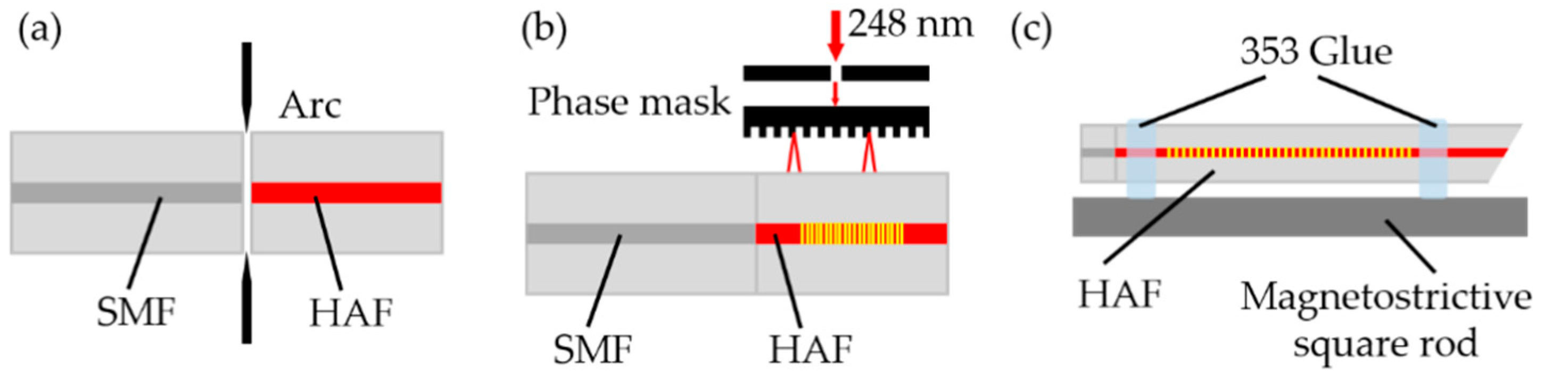
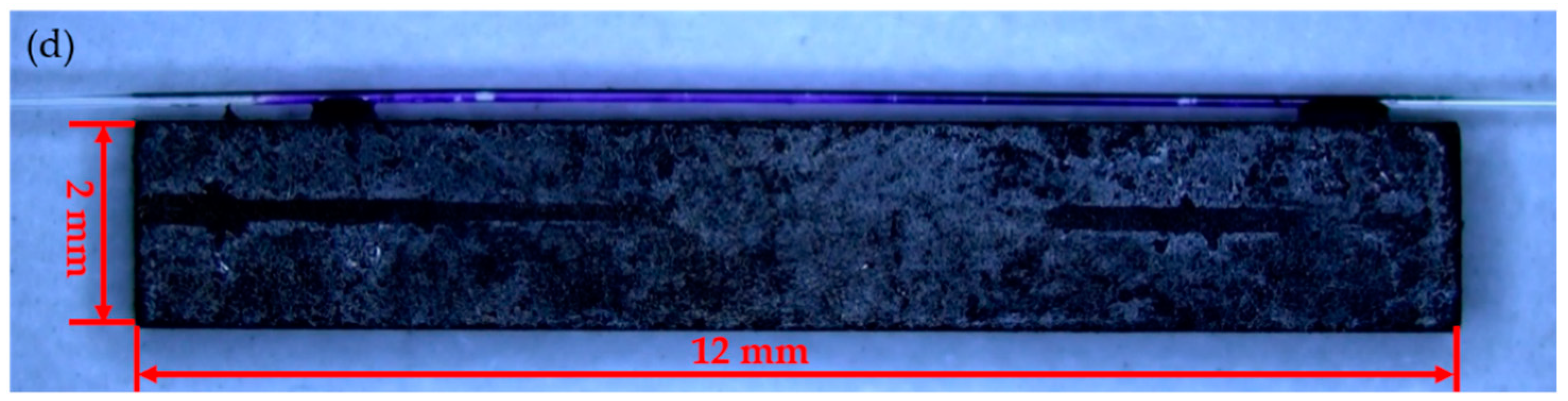
3.1. Fabrication Process

Figure 1a–c shows the steps of the sensor fabrication process. Firstly, an HAF (Coractive, Quebec, QC, Canada; ATN-FB-22.1-2.6) was pre-treated by hydrogen loading to enhance its photosensitivity, and then it was spliced to a standard single-mode fiber (Corning, New York, NY, USA; SMF-28) by a commercial fusion splicer (FITEL, Tokyo, Japan; S178) (Figure 1a). Secondly, a section of the HAF was exposed by an excimer laser (Coherent, Santa Clara, CA, USA; Bragg Star S-Industrial, 248 nm) using a phase-mask with a pitch of 1072.88 nm to inscribe a segment of Bragg grating on the core of the HAF (Figure 1b). The length, original Bragg wavelength λB, and full width at half maxima (FWHM) of λB of the fabricated HAFBG are 10 mm, 1549.50 nm, and 0.20 nm, respectively. To avoid Fresnel reflections, the other end-face of the HAF is cleaved at an 8° angle and the remaining HAF length is about 12 mm. Thirdly, the fabricated HAFBG sample and a prepared magnetostrictive rod with a square cross-section were placed on two separate three-dimensional manual adjustment stages and adjusted until the HAFBG was suspended above the magnetostrictive rod, after which two drops of 353ND glue (Epoxy Technology, Billerica, MA, USA) were applied in the gap between the HAF and the magnetostrictive rod (Figure 1c). The 353ND glue is obtained by mixing the 353ND Part A and Part B with a weight ratio of 10:1. The distance between the two glue fixation points, that is, the effective sensing length, is around 10 mm. A microscope image of the fabricated sensor is shown in Figure 1d. The magnetostrictive rod is made by Terfenol-D (Suzhou A-one Special Alloy, Suzhou, China), which has a high saturation flux density of around 1 T, a high magnetostriction coefficient of over 1000 × 10−6, an ultralow resistivity of 60 × 10−8 Ohm-meters, and a thermal expansion coefficient of about 11 ppm/°C @ 25 °C. The length of the magnetostrictive rod is 12 mm, and the square cross-section is 2 × 2 mm2.

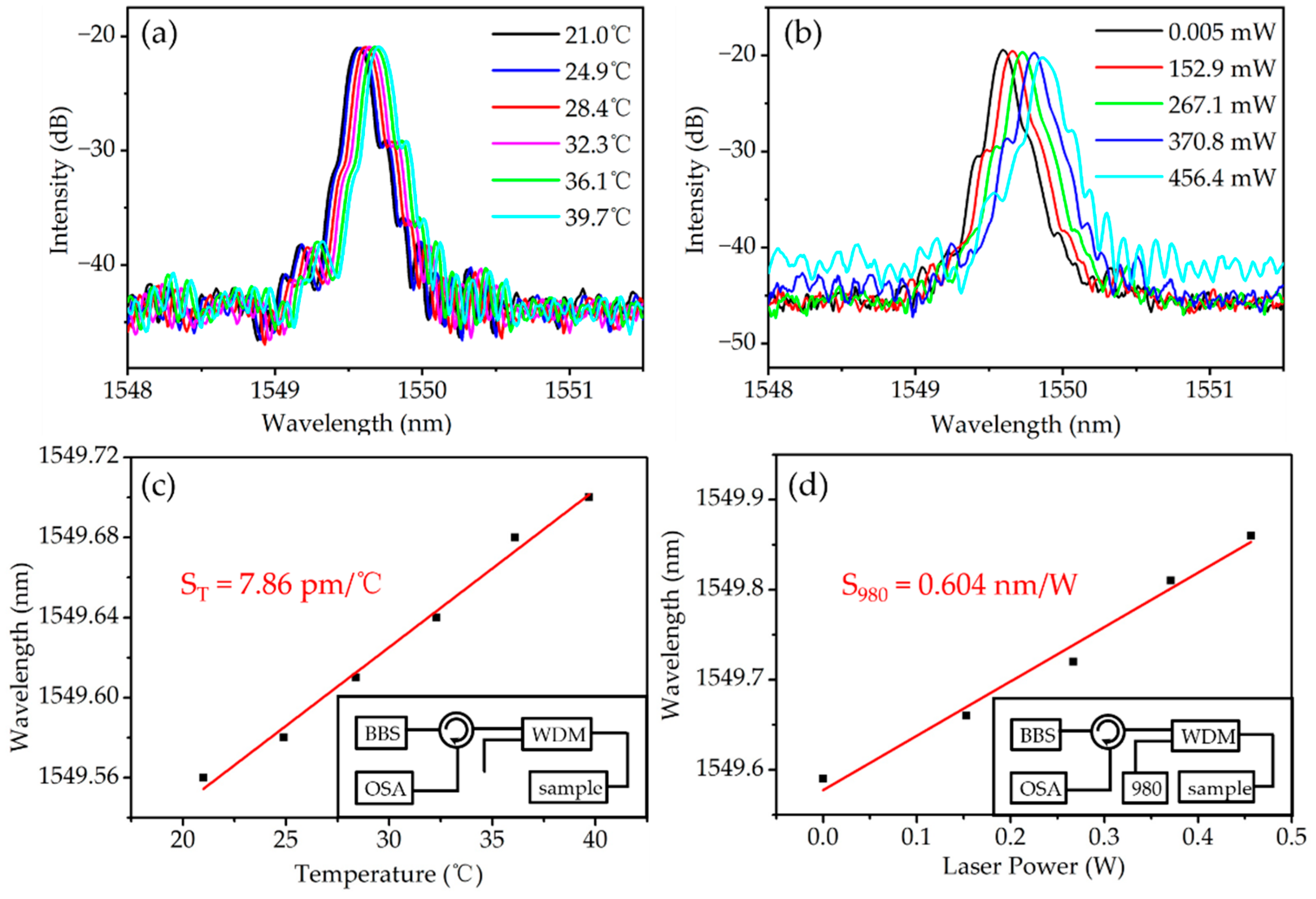
3.2. Sensor Characterization

Figure 2a,b shows measured reflection spectra of the fabricated sensor and Figure 2c,d shows the corresponding temperature and heating laser power responses of the HAFBG Bragg wavelength. For the temperature response measurement, the spectra were measured by using a board band source (BBS, Dense Light, Tanah Merah, Singapore; DL-BX9-CS5169A) with an output wavelength range of 1250–1630 nm, a circulator (DK photonics, Shenzhen, China; MCCIR-3-CL-FA), a wavelength division multiplexer (WDM, 1550/980 ± 20 nm), and an optical spectrum analyzer (OSA; Yokogawa, Osaka, Japan; AQ6317) with a minimum wavelength resolution of 0.01 nm, arranged as shown in the inset of Figure 2c. For the heating laser power response measurement, light emitted from the BBS reaches the 1550 nm port of the WDM through the circulator, and at the same time, light emitted from a heating laser (Feibo optoelectronic technology, Shenzhen, China; FL-980nm-600mW-M-FA) enters at the 980 nm port of the WDM, and then the merged light propagates together to the sensor, as shown in the inset of Figure 2d. Reflection spectra are measured by the OSA. A tunable incubator (Shanghai Gixin Scientific Instrument, Shanghai, China; LRH-150) was used to change the ambient temperature around the sensor, and a thermometer (Chuangjimei, Hengshui, China; TP301) was used for real-time temperature monitoring. Each temperature setting is kept unchanged for at least 5 min to ensure a stable reflection spectrum. As shown in Figure 2c, the sensor shows a linear response to ambient temperature, and a temperature sensitivity ST of 7.86 pm/°C was obtained by linear fitting of the data of the Bragg wavelength shift to the ambient temperature. Therefore, during the process of dynamic parameter measurement, such as the AC magnetic field measurement, the preset optimal working point will move when the ambient temperature changes, resulting in unstable and incorrect measurement results. The operating point can be stabilized by regulating the power of a heating laser targeted on the HAF using a control algorithm to compensate the temperature fluctuations of the surrounding environment.
An experiment measuring the HAFBG Bragg wavelength shift due to the heating laser power was conducted to verify the feasibility of stabilizing the operating point of the sensor. The Bragg wavelength responses of the sensor to various pump powers of the heating laser are shown in Figure 2d. Measurements were made with the heating laser powers set to 152.9 mW, 267.1 mW, 370.8 mW, and 456.4 mW at an ambient temperature of 16.9 °C. The Bragg wavelength of the sensor is correspondingly shifted from 1549.59 nm to 1549.86 nm. The tuning coefficient S980 of the heating laser is calculated to be 0.604 nm/W by linear fitting of the Bragg wavelength shift to the heating laser power. Following references [36,37], the heat generated by the heating laser power can be expressed as:
Q ( z ) = k α P 0 e α z ,
where Q is the heat; z is the position along axial direction of the HAFBG; α is the absorption coefficient of the core of the HAF, which is measured to be 3.325 dB/cm @ 980 nm; P0 is the power of the incident pump laser; and k is the thermal conversion coefficient from optical power to heat, which is about 38%. The distribution of heat Q is not uniform and there exists a temperature gradient along the z-axis of the HAFBG [36]. Thus, a larger laser power will slightly widen the Bragg grating spectrum due to the nonuniform temperature distribution along the HAFBG.
The DC magnetic field response of the sensor was also measured. As shown in Figure 3a, a parallel magnetic field was generated by a Helmholtz coil (Hunan Paisheng Technology, Changsha, China; PS4000c) with different electric current. A Tesla meter (AIPLI, Quzhou, China; KT-101) was placed near the sensor to monitor the magnetic field intensity, and an FBG demodulator (CASSTK, Shenzhen, China; SAI-4YX3AL) was used to monitor and record the shift of the HAFBG peak in real time. The magnetostrictive square rod is stretched by the increasing magnetic field intensity, causing an increase in the HAFBG period and a red shift in the Bragg wavelength, as seen in Figure 3b. The fitting magnetic field response curve shows a quadratic function shape, expressed as λ = 1549.57 − 1.79 × 10⁻⁴·B + 4.39 × 10⁻⁴·B2, which is mainly caused by the natural nonlinear response of giant magnetostrictive materials [16]. For a low magnetic field range from 0 to 2.5 mT, the approximate linear sensitivity Slow is about 0.84 pm/mT, and for a high magnetic field range from 3.5 to 6 mT, the approximate linear sensitivity Shigh is about 3.95 pm/mT.

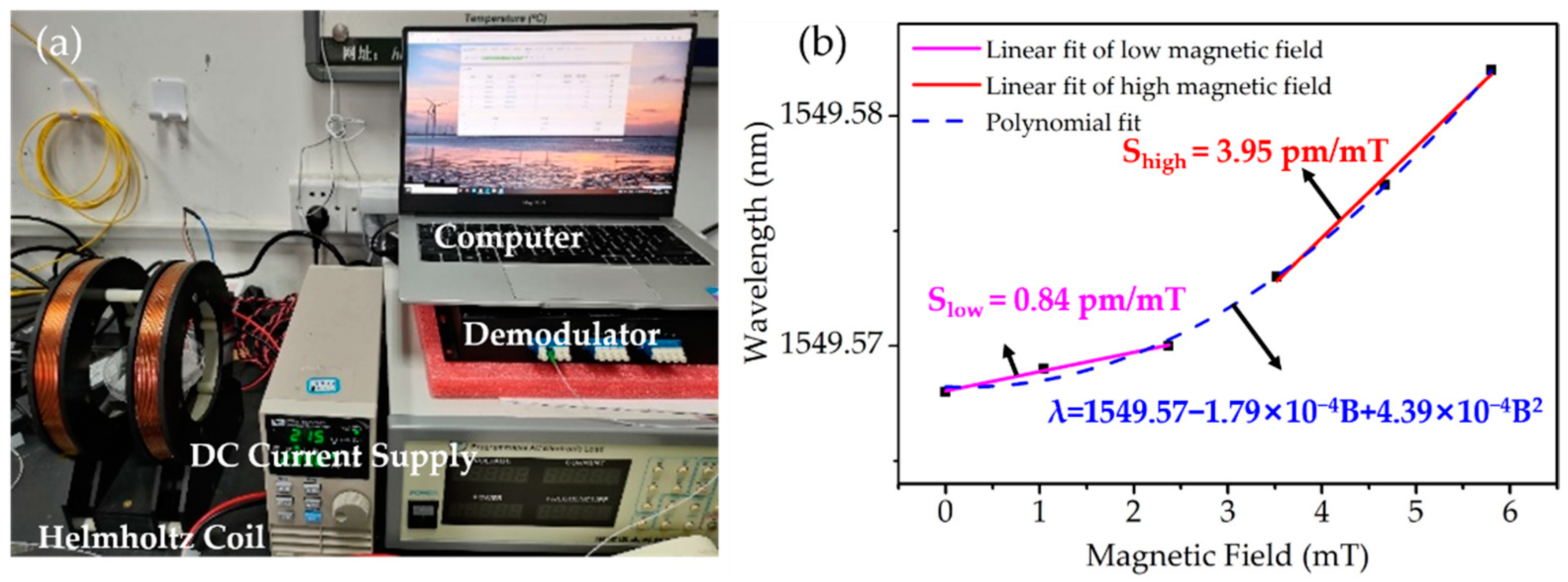
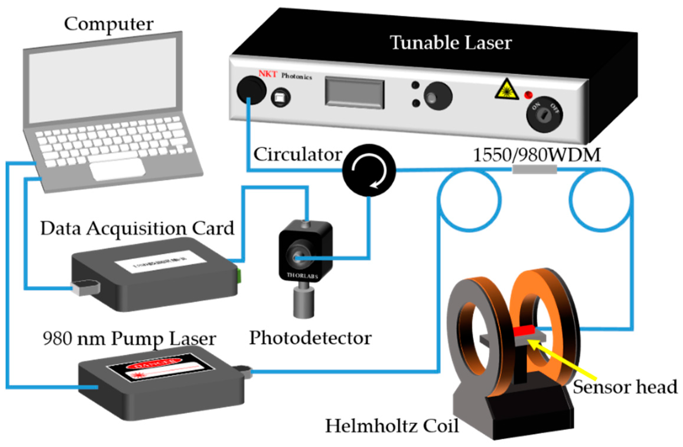
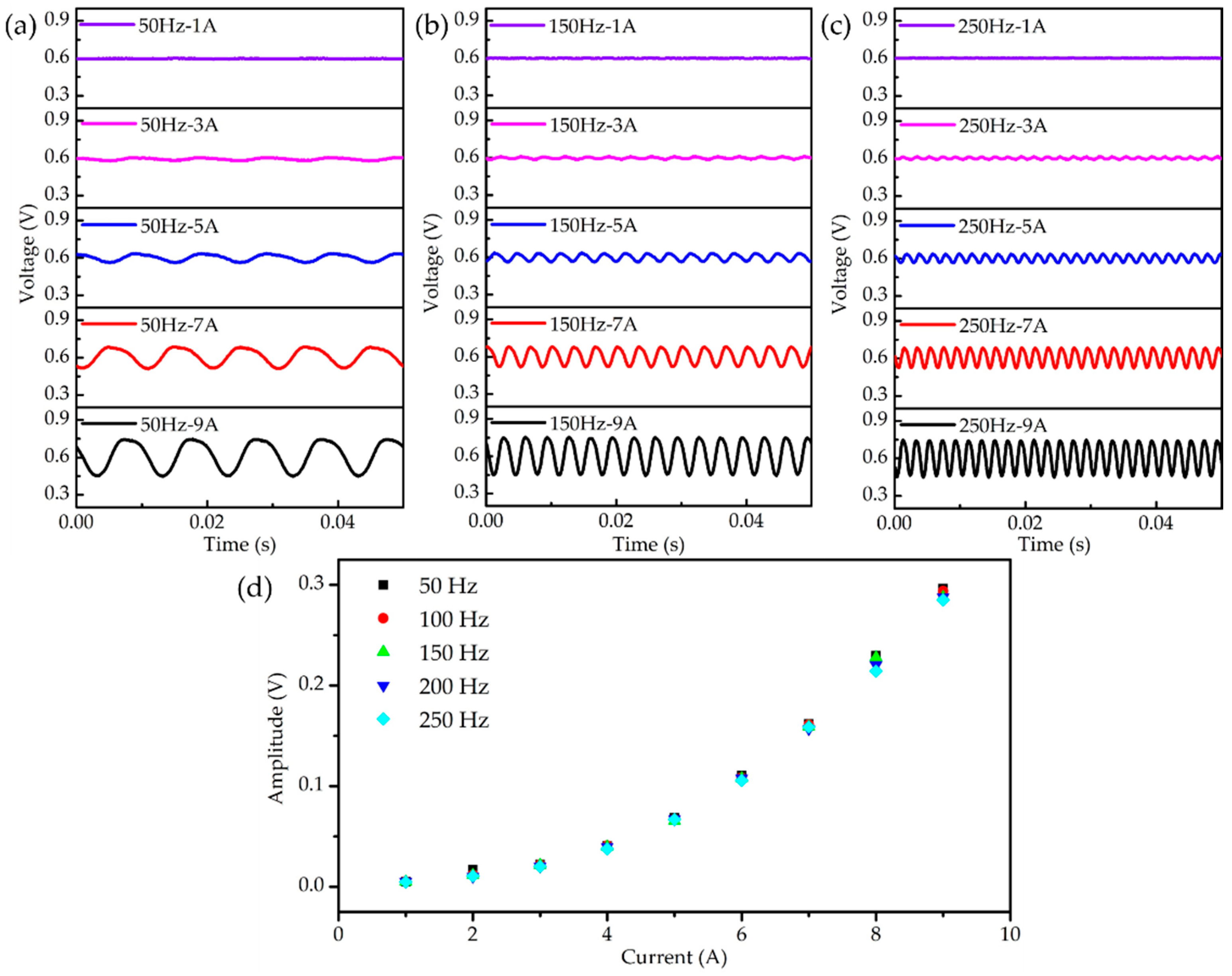
3.3. AC Magnetic Field Sensing and Stable Operating-Point Performance

An AC magnetic field can be monitored by measuring the Bragg wavelength shift of the HAFBG of the sensor. However, the measurement of the HAFBG spectrum requires an OSA or another wavelength demodulation device, which is relatively expensive and has slow signal acquisition frequency. Thus, to realize relatively fast and low-cost AC magnetic field monitoring, we opted to measure the optical intensity instead of the optical spectrum using a setup based on the edge filter principle, as depicted in Figure 4. The sensor is placed in the center of a Helmholtz coil, which is driven by an AC frequency conversion power supply to generate uniform a magnetic field at varying frequencies. The output wavelength of a narrow linewidth fiber laser (NKT Photonics, Cologne, German; Koheras Boostik E15) is adjusted to the wavelength located in the slope of the HAFBG spectrum. The signal reflected from the sensor is detected by a photoelectric detector (Thorlabs, Newton, MA, USA; PDA50B2), and data are sent to a computer by a data acquisition card (ART technology, Beijing, China; USB-3106A) with a sampling rate of 10,000 Sa/s. A 980 nm pump laser is used as a heating laser, as was introduced in the previous experiment. A computer application program designed using LabVIEW is used for control and communication with the data acquisition card and the heating laser.
Figure 5 plots voltage waveforms measured by the data acquisition card when the sensor is used to monitor the AC magnetic field drive by different oscillation frequencies and currents. All the signals detected by the sensor show a periodic waveform, with a frequency twice that of the AC magnetic field. Note that the magnetostrictive square rod elongates as the strength of the magnetic field increases along the length of the rod. As the magnetic field strength decreases, the magnetostrictive square rod shortens to its original length, i.e., the magnetostrictive rod stretches twice during one period of magnetic field oscillation, and thus the frequency of the magnetic field generated by the coil will be doubled in the sample. The wavelength of the narrow linewidth fiber laser is set to be in the middle of the slope of the sample spectrum to achieve as high a detection sensitivity and as large a detection range as possible. It should be noted that lights from the 980 nm heating laser at different powers are added through the circulator to ensure a stable operating point. Figure 5d shows that the measured peak-to-peak amplitude of waveform increase with driving currents and is independent of AC magnetic field frequency.
Referring to Figure 6, the operating principle and process of maintaining a stable operating point are described in the following. Prior to the experiment, an initial heating pump power Pinit_980 is set (here to 100 mW). The wavelength of the narrow linewidth fiber laser sweeps the entire HAFBG spectral range, and the corresponding received voltage signal V as a function of wavelength λ is recorded, i.e., f (λ, V). The midpoint voltage Vm is then set as the optimal operating point that is desired to be kept stable. During AC magnetic field detection, a Proportional–Integral–Differential (PID) control algorithm is used to adjust the power of the heating laser, keeping the average value Vavg of the received signal (the measured value in the PID algorithm) always close to the operating point Vm (the reference value in the PID algorithm) at all times by adjusting the proportionality coefficient KP, the integral coefficient KI, and the differential coefficient KD.
To verify the performance of the proposed stable operating point algorithm based on PID control, the sample is placed in an incubator, which is used to simulate a varying ambient temperature. Figure 7 shows measured voltage signals when the driving current and frequency of the coil are set to 9 A and 50 Hz, respectively, and temperature is varied in the range 22.2–41.6 °C. It should be noted that the received signals were recorded at several random temperatures, and the operating point was kept stable during the temperature rising process. The whole heating process took about 40 min and the temperature rising rate is calculated as about 0.48 °C/min. Figure 7a shows results when the PID control algorithm was not used; the received signal drifts significantly with the variation in ambient temperature, and is even distorted. Figure 7b shows results when the PID is used to control the heating laser power, and it can be clearly seen that the signals are well stabilized at the operating point while the temperature is changed by more than 15 °C. The PID control parameters for this test were KP = 12, KI = 0.05, and KD = 0.02. As can be seen in Figure 2d, the maximum wavelength shift Δλmax caused by the tunable heating laser power ΔP980 can be calculated as:
Δ λ max = Δ P 980 × S 980 = 120.8 pm ,
Thus, the theoretical maximum temperature range ΔTmax that can be compensated by adjusting the heating laser power is:
Δ T max = Δ λ max / S T = 15.36 ° C .
which is consistent with the experimental results seen in Figure 7. The initial power of the heating laser used in the experiment is 100 mW, and the adjustable range is 0–200 mW. The adjustable temperature range can be expanded by increasing the laser power; however, the laser power should not be too large, otherwise the loss and the bandwidth of the spectrum will increase due to non-uniform heating of the HAF.

4. Conclusions

In this paper, an optical fiber Bragg grating sensor attached to a magnetostrictive rod that has a stable operating point for AC magnetic field measurement was proposed, fabricated, and characterized. The performance of the sensor was measured under different ambient temperatures and different heating laser powers, as well as different DC magnetic field intensities and different AC magnetic field drive currents and frequencies. The calibration results show that the sensitivities of temperature, heating laser power, and magnetic field intensity are 7.86 pm/°C, 0.604 nm/W, and 3.95 pm/mT, respectively. Dynamic measurement results confirm that the sensor can maintain a stable operating point using a PID control algorithm when the temperature is changed by more than 15 °C. Given that the sensor is insensitive to ambient temperature fluctuations, it is well suited for practical applications in AC magnetic sensing, e.g., for health monitoring of transformers and fault diagnosis of induction motors.

Author Contributions

Conceptualization, S.W. and S.H.; methodology, S.W. and S.H.; software, S.W., X.C. and H.L.; validation, S.W., L.L. and S.H.; formal analysis, X.C.; investigation, X.C., H.L. and S.W.; resources, S.H.; data curation, X.C.; writing—original draft preparation, X.C.; writing—review and editing, S.W., E.F. and S.H.; visualization, X.C.; supervision, S.W. and S.H.; project administration, S.H.; funding acquisition, S.H. All authors have read and agreed to the published version of the manuscript.

Funding

This work was supported partially by the Key Research and Development Program of Zhejiang Province (2021C03178), the Guangdong Innovative Research Team Program (under grant 201001D0104799318), the Ningbo Science and Technology Project (2021Z030), the National Key Research and Development Program of China (no. 2018YFC1407503), the Ningbo Science and Technology Plan Project-Key Core Technology Emergency Tackling Plan Project (2020G012), the China Postdoctoral Science Foundation (no. 2018M642423), and the Shanghai Zhangjiang Science City Special Development Fund.

Institutional Review Board Statement

Not applicable.

Informed Consent Statement

Not applicable.

Data Availability Statement

Not applicable.

Conflicts of Interest

The authors declare no conflict of interest.

References

  1. Lenz, J.; Edelstein, A.S. Magnetic sensors and their applications. IEEE Sens. J. 2006, 6, 631–649. [Google Scholar] [CrossRef]
  2. Bieler, G.; Werneck, M.M. A magnetostrictive-fiber Bragg grating sensor for induction motor health monitoring. Measurement 2018, 122, 117–127. [Google Scholar] [CrossRef]
  3. Dante, A.; David, J.; Cremonezi, A.O.; Bacurau, R.M.; Werneck, M.M. Fiber-optic current sensor based on FBG and Terfenol-D with magnetic flux concentration for enhanced sensitivity and linearity. IEEE Sens. J. 2020, 20, 3572–3578. [Google Scholar]
  4. Ding, G.; Zhang, S.; Cao, H.; Gao, B.; Zhang, B. Flux density measurement of radial magnetic bearing with a rotating rotor based on fiber Bragg grating-giant magnetostrictive material sensors. Appl. Opt. 2017, 56, 4975–4981. [Google Scholar] [CrossRef]
  5. Kaidarova, B.A.; Liu, W.; Swanepoel, L.; Almansouri, A.; Geraldi, N.R.; Duarte, C.M.; Kosel, J. Flexible Hall sensor made of laser-scribed graphene. Npj Flex. Electron. 2021, 5, 2. [Google Scholar] [CrossRef]
  6. Jogschies, L.; Klaas, D.; Kruppe, R.; Rittinger, J.; Taptimthong, P.; Wienecke, A.; Rissing, L.; Wurz, M.C. Recent developments of magnetoresistive sensors for industrial applications. Sensors 2015, 15, 28665–28689. [Google Scholar] [CrossRef] [Green Version]
  7. Henry, S.; di Borgo, E.P.; Cavaillou, A. Tracking geomagnetic fluctuations to picotesla accuracy using two superconducting quantum interference device vector magnetometers. Rev. Sci. Instrum. 2013, 84, 024501. [Google Scholar] [CrossRef]
  8. Zhou, X.; Li, X.; Li, S.; An, G.; Cheng, T. Magnetic field sensing based on SPR optical fiber sensor interacting with magnetic fluid. IEEE Trans. Instrum. Meas. 2019, 68, 234–239. [Google Scholar] [CrossRef]
  9. Alberto, N.; Domingues, M.F.; Belo, J.H.; Marques, C.; Antunesa, P.; Amaral, V.; Andre, P. Optical fibre fuse effect based sensor for magnetic field monitoring. In Proceedings of the Spie Optics + Optoelectronics, Prague, Czech Republic, 1–4 April 2019; Volume 110281S. [Google Scholar]
  10. Liu, C.; Shen, T.; Wu, H.; Feng, Y.; Chen, J. Applications of magneto-strictive, magneto-optical, magnetic fluid materials in optical fiber current sensors and optical fiber magnetic field sensors: A review. Opt. Fiber Technol. 2021, 65, 102634. [Google Scholar] [CrossRef]
  11. Thakur, H.V.; Nalawade, S.M.; Gupta, S.; Kitture, R.; Kale, S.N. Photonic crystal fiber injected with Fe3O4 nanofluid for magnetic field detection. Appl. Phys. Lett. 2011, 99, 161101. [Google Scholar] [CrossRef]
  12. Dai, J.; Yang, M.; Li, X.; Liu, H.; Tong, X. Magnetic field sensor based on magnetic fluid clad etched fiber Bragg grating. Opt. Fiber Technol. 2011, 17, 210–213. [Google Scholar] [CrossRef]
  13. Davino, D.; Visone, C.; Ambrosino, C.; Campopiano, S.; Cusano, A.; Cutolo, A. Compensation of hysteresis in magnetic field sensors employing fiber Bragg grating and magneto-elastic materials. Sens. Actuator A Phys. 2008, 147, 127–136. [Google Scholar] [CrossRef]
  14. Yang, M.; Dai, J.; Zhou, C.; Jiang, D. Optical fiber magnetic field sensors with TbDyFe magnetostrictive thin films as sensing materials. Opt. Express 2009, 17, 20777–20782. [Google Scholar] [CrossRef]
  15. Quintero, S.; Braga, A.; Weber, H.; Bruno, A.; Araújo, J. A magnetostrictive composite-fiber Bragg grating sensor. Sensors 2010, 10, 8119–8128. [Google Scholar] [CrossRef] [PubMed] [Green Version]
  16. Liu, H.; Or, S.W.; Tam, H.Y. Magnetostrictive composite–fiber Bragg grating (MC–FBG) magnetic field sensor. Sens. Actuator A Phys. 2012, 173, 122–126. [Google Scholar] [CrossRef]
  17. Zhao, Q.; Dai, Y.; Li, T.; Liu, B.; Yang, M.; Yin, G. Femtosecond laser ablation of microstructures in fiber and application in magnetic field sensing. Opt. Lett. 2014, 39, 1905–1908. [Google Scholar] [CrossRef]
  18. Zhang, P.; Tang, M.; Gao, F.; Zhu, B.; Fu, S.; Ouyang, J.; Zhao, Z.; Wei, H.; Li, J.; Shum, P.P.; et al. An ultra-sensitive magnetic field sensor based on extrinsic fiber-optic Fabry–Perot interferometer and Terfenol-D. J. Light. Technol. 2015, 33, 3332–3337. [Google Scholar] [CrossRef]
  19. Lopez, J.D.; Dante, A.; Bacurau, R.M.; Cremonezi, A.Q.; Mok, R.W.; Carvalho, C.C.; Allil, R.C.S.B.; Ferreira, E.C.; Werneck, M.M. Fiber-optic current sensor based on FBG and optimized magnetostrictive composite. IEEE Photon. Technol. Lett. 2019, 31, 1987–1990. [Google Scholar] [CrossRef]
  20. Lopez, J.D.; Dante, A.; Carvalho, C.C.; Allil, R.C.S.B.; Werneck, M.M. Simulation and experimental study of FBG-based magnetic field sensors with Terfenol-D composites in different geometric shapes. Measurement 2020, 172, 108893. [Google Scholar] [CrossRef]
  21. Sun, L.; Jiang, S.; Zuegel, J.D.; Marciante, J.R. Effective Verdet constant in a terbium-doped-core phosphate fiber. Opt. Lett. 2009, 34, 1699–1701. [Google Scholar] [CrossRef]
  22. Crassee, I.; Levallois, J.; Walter, A.L.; Ostler, M.; Bostwick, A.; Rotenberg, E.; Seyller, T.; van der Marel, D.; Kuzmenko, A.B. Giant Faraday rotation in single- and multilayer graphene. Nat. Phys. 2011, 7, 48–51. [Google Scholar] [CrossRef] [Green Version]
  23. Son, C.; Ju, H. Magnetic control of optical reflectance from metallic thin film using surface plasmon resonance and Faraday rotation. Materials 2021, 14, 3354. [Google Scholar] [CrossRef] [PubMed]
  24. Parsa, N.; Gasper, M.R.; Amacher, B.C.; Toonen, R.C. Millimeter-wave Faraday rotation from ferromagnetic nanowires. IEEE Trans. Nanotechnol. 2019, 18, 839–844. [Google Scholar] [CrossRef]
  25. Xia, J.; Wang, Q.; Liu, X.; Luo, H. Fiber optic Fabry-Perot current sensor integrated with magnetic fluid using a fiber Bragg grating. Sensors 2015, 15, 16632–16641. [Google Scholar] [CrossRef] [Green Version]
  26. Zhao, Y.; Wang, X.; Lv, R.; Li, G.; Zheng, H.; Zhou, Y. Highly sensitive reflective Fabry-Perot magnetic field sensor using magnetic fluid based on Vernier effect. IEEE Trans. Instrum. Meas. 2020, 70, 7000808. [Google Scholar] [CrossRef]
  27. Zu, P.; Chan, C.C.; Lew, W.S.; Hu, L.; Jin, Y.; Liew, H.F.; Chen, L.; Wong, W.; Dong, X. Temperature-insensitive magnetic field sensor based on nanoparticle magnetic fluid and photonic crystal fiber. IEEE Photon. J. 2012, 4, 491–498. [Google Scholar]
  28. Zhang, Y.; Pu, S.; Li, Y.; Hao, Z.; Li, D.; Yan, S.; Yuan, M.; Zhang, C. Magnetic field and temperature dual-parameter sensor based on nonadiabatic tapered microfiber cascaded with FBG. IEEE Access 2022, 10, 15478–15486. [Google Scholar] [CrossRef]
  29. Mohammed, A.; Melecio, J.I.; Djurović, S. Electrical machine permanent magnets health monitoring and diagnosis using an air-gap magnetic sensor. IEEE Sens. J. 2020, 20, 5251–5259. [Google Scholar] [CrossRef]
  30. Peng, J.; Zhang, S.; Jia, S.; Kang, X.; Yu, H.; Yang, S.; Wang, S.; Yang, Y. A highly sensitive magnetic field sensor based on FBG and magnetostrictive composite with oriented magnetic domains. Measurement 2022, 189, 110667. [Google Scholar] [CrossRef]
  31. Yoffe, G.W.; Krug, P.A.; Ouellette, F.; Thorncraft, D.A. Passive temperature compensating package for optical fiber gratings. Appl. Opt. 1995, 34, 6859–6861. [Google Scholar] [CrossRef]
  32. Liu, Q.; Jing, Z.; Liu, Y.; Li, A.; Zhang, Y.; Huang, Z.; Han, M.; Peng, W. Quadrature phase-stabilized three-wavelength interrogation of a fiber-optic Fabry-Perot acoustic sensor. Opt. Lett. 2019, 44, 5402–5405. [Google Scholar] [CrossRef] [PubMed]
  33. Mora, J.; Diez, A.; Cruz, J.L.; Andres, M.V. Magnetostrictive Sensor Interrogated by Fiber Gratings for DC-Current and Temperature Discrimination. IEEE Photonics Technol. Lett. 2000, 12, 1680–1682. [Google Scholar] [CrossRef]
  34. Ma, R.; Zhang, W.; Wang, Z.; Huang, W.; Li, F. Magnetic sensor based on Terfenol-D materials and fiber Bragg grating Fabry-Perot cavity. Acta Photonics Sin. 2018, 47, 0306006. [Google Scholar]
  35. Kersey, A.D.; Davis, M.A.; Patrick, H.J.; LeBlanc, M.; Koo, K.P.; Askins, C.G.; Putnam, M.A.; Friebele, E.J. Fiber grating sensors. J. Light. Technol. 1997, 15, 1442–1463. [Google Scholar] [CrossRef] [Green Version]
  36. Li, Y.; Yan, G.; Zhang, L.; He, S. Microfluidic flowmeter based on micro “hot-wire” sandwiched Fabry-Perot interferometer. Opt. Express 2015, 23, 9483–9493. [Google Scholar] [CrossRef] [PubMed]
  37. Wu, S.; Xie, L.; Lin, H.; Tan, Q.; Chen, X.; He, S. Fiber acoustic sensor with stable operating-point based on a photo-thermal cavity. IEEE Sens. J. 2022, 22, 1321–1326. [Google Scholar] [CrossRef]
Figure 1. (ac) Fabrication process schematic diagram of the proposed sensor. (d) Microscope image of the side view of the fabricated sensor.
Applsci 12 07049 g001aApplsci 12 07049 g001b
Figure 2. (a) Measured spectra of the sensor corresponding to the ambient temperature in the range 21.0–39.9 °C. (b) Measured spectra of the sensor corresponding to the heating laser power in the range 0.005–456.4 mW. (c) Ambient temperature response of the HAFBG Bragg wavelength. Inset: Schematic diagram of the experimental setup for temperature measurement. (d) Heating laser power response of the HAFBG Bragg wavelength. Inset: Schematic diagram of the experimental setup for heating laser power measurement.
Applsci 12 07049 g002
Figure 3. (a) Experimental system setup for DC magnetic field sensing. (b) Bragg wavelength shift of the HAFBG as a function of DC magnetic field intensity.
Applsci 12 07049 g003
Figure 4. Experimental system setup for AC magnetic field measurement.
Applsci 12 07049 g004
Figure 5. Measured voltage waveforms when the frequency of the AC magnetic field is (a) f = 50 Hz, (b) f = 150 Hz, and (c) f = 250 Hz. The drive currents of AC frequency conversion power supply are 1 A, 3 A, 5 A, 7 A, and 9A, respectively. (d) Variation in peak-to-peak amplitude of waveform with driving currents when the frequencies of AC magnetic field are 50, 100, 150, 200, and 250 Hz, respectively.
Applsci 12 07049 g005
Figure 6. Operating principle and process of maintaining a stable operating point: (a) a recorded mean below Vm prompts a reduction in the heating laser power, and (b) a recorded mean larger than Vm prompts an increase. (The red line represents the original voltage signal with initial heating power; the orange line represents the changed voltage signal with changed heating power).
Applsci 12 07049 g006
Figure 7. Signals at different temperatures without (a) and with (b) the PID control.
Applsci 12 07049 g007
Table 1. Comparison of the representative FBG-based magnetic field sensors.
ReferencesYearSensing StructureEffective Sensing Length (mm)Sensitivity (pm/mT)Temperature Compensation Method
[12]2011Etched FBG immersed in magnetic fluidNo mention3.44No
[14]2009Etched FBG coated with TbDyFe/FeNi thin film151.08A separate FBG temperature sensor
[33]2000Standard FBG bonded onto Terfenol–D alloy surface258.68A separate FBG temperature sensor
[20]2021FBG embedded in Terfenol–D composite162.70A separate FBG temperature sensor
[30]2022FBG embedded in Terfenol–D composite 409.83No
This work HAFBG bonded onto Terfenol-D alloy surface103.95Photo-thermal effect of HAF
Publisher’s Note: MDPI stays neutral with regard to jurisdictional claims in published maps and institutional affiliations.

