Article

Structural Design and Lubrication Properties under Different Eccentricity of Magnetic Fluid Bearings

1
School of Mechanical Engineering, Anhui Polytechnic University, Wuhu 241000, China
2
National Key Laboratory Science Technology of Helicopter Transmission, Nanjing University of Aeronautics and Astronautics, Nanjing 210016, China
*
Author to whom correspondence should be addressed.
Appl. Sci. 2022, 12(14), 7051; https://doi.org/10.3390/app12147051
Submission received: 27 May 2022 / Revised: 7 July 2022 / Accepted: 11 July 2022 / Published: 13 July 2022
(This article belongs to the Special Issue Tribology and Mechanical Transmissions)

Abstract

:
As a lubricant, the viscosity of the magnetic fluid changes with the external magnetic field, which improves the bearing capacity of the oil film and hence the lubrication effect, and has a promising application in bearings. Based on the Roelands viscosity theory, the Shliomis model is used to derive the viscous temperature, viscous pressure, and magnetic viscosity characteristics of magnetic fluids under the influence of an applied magnetic field, and further proposes a structural model of magnetic fluid lubricated bearings to investigate the pressure, temperature and magnetic intensity distribution of magnetic fluids under different eccentricity conditions. The results show that the viscosity of the magnetic fluid decreases exponentially with increasing temperature, rises linearly with increasing pressure, and increases and stabilizes with increasing magnetic induction strength. Because the minimum film thickness point is the dividing point between the convergent wedge and the dispersed wedge, the pressure distribution of the lubricant film separates high pressure from low pressure at the minimum film thickness, and the differential pressure increases with the increase in eccentricity. The temperature distribution of the high-temperature zone is mainly distributed in the middle of the film, and the minimum film thickness zone and the maximum temperature increases with the increase in eccentricity. The magnetic intensity distribution of the strong magnetic field is mainly concentrated in the minimum film thickness zone, and the magnetic induction intensity increases with the increase in eccentricity. The results of this study have certain research significance for solving the problem of the poor lubrication effect of bearing lubricant due to high temperature.

1. Introduction

As a core component of mechanical transmission systems, bearings are widely used in aerospace and other fields, and their reliability is highly dependent on lubrication. However, in the complex working conditions in aerospace and other fields, traditional lubricants as a lubricating medium inevitably encounter high temperature conditions leading to a reduction in viscosity and seriously affecting the lubrication effect of the bearings. In the case of journals operating at high speeds, the pressure of the lubricant is much higher than the external pressure, resulting in end drains and the need to continuously refill the bearing with lubricant, resulting in a cumbersome operation and waste of resources. Magnetic fluids can be used to prevent the loss of lubricant by providing directional lubrication in a fixed field [1,2], at the same time, by adjusting the magnetic field strength, the viscosity of the magnetic fluid will also change [3,4], which can regulate the change in viscosity due to environmental factors such as high temperatures and achieve active lubrication.
Magnetic fluids are new smart materials with superparamagnetic properties formed by the homogeneous dispersion of magnetic nanoparticles attached to surfactants in a carrier fluid. Because of their unique rheology and controllable advantages, they are used in areas such as damping, vibration damping and rotation [5,6,7]. The unique rheology of the magnetic fluid has brought ideas to researchers at home and abroad to design new magnetic fluid lubricated bearings. Shah et al. [8] investigated the dynamic and static performance of long journal bearings lubricated with magnetic fluids compared to conventional lubricants using journal rotation and translation, and found that bearings lubricated with magnetic fluids had a lower coefficient of friction and higher load carrying capacity. The rheological properties of magnetic fluids can respond rapidly to changes in the magnetic field and have promising applications in active lubrication [6]. Its unique rheological properties have given domestic and international researchers ideas to design new magnetic fluid lubricated bearings. Zapoměl et al. [9] proposed a composite fluid–lubricated hydrodynamic bearing that could control the performance of the bearing by varying the magnetic field strength. It was found that the magnetic field strength increased, the magnetic fluid oil film carrying capacity increased, and the journal moved towards the center of the bearing, improving the reliability of the bearing. Shah [10] investigated the effect of frictional sub roughness on magneto–fluid lubricated disc extrusion oil film bearings, and found that porous annular disc extrusion bearings with high roughness had greater load carrying capacity and better bearing performance. Wang et al. [11] proposed a magnetorheological fluid lubricated floating ring bearing and tested the vibration suppression effect of the bearing under the action of an applied magnetic field using a magneto rheometer, and the results showed that the magnetorheological fluid lubricated floating ring bearing has a good vibration suppression effect. Patel et al. [12] used magnetic fluids and conventional lubricants in the same bearing lubrication system for a comparative performance study, which concluded that magnetic fluid lubrication has better load–bearing capacity and still has load–bearing capacity for journals under magnetic fluid non–flow conditions. Urreta et al. [13] used software simulations and experimental verification analysis to conclude that the use of magnetic fluid lubrication can significantly improve the performance of hybrid journal bearings. Patel et al. [14] designed a hydrodynamic radial bearing based on magnetic fluid lubrication. A comparative analysis with conventional lubricants showed that the magnetic fluid lubricated bearing has a higher load carrying capacity, lower temperature rise and significantly improved bearing performance. Quinci et al. [15] studied the performance associated with magnetic fluid lubrication radial bearings: journal low speed increase field strength viscosity increases, thus obtaining a thicker lubricant film; journal high speed reduce the magnetic field magnetic fluid viscosity decreases thus reducing friction losses, compared with ordinary oil lubrication; magnetic fluid lubrication can achieve active control of hydrodynamic lubrication bearings. Kataria et al. [16] designed different stator plain bearings considering the effects of extrusion speed and skew–variable magnetic fields, and obtained through comparative mathematical analysis that cut–line pad stator plain bearings can maximize the performance of the system. Huang et al. [17,18,19,20] proposed a variety of magnetic fluid support and lubrication bearing structures, through single ring, four rings and multi–ring array structures, combined with the change in magnetic field direction and whether the ring is sealed to explore the support force and lubrication effect. The results show that the multi–ring array form both static support force and lubrication effect are significantly improved, the adjacent magnetic field direction between the opposite ring has better load–bearing capacity, and the magnetic ring seal state support capacity is stronger, with a better lubrication effect. It can be seen that magnetic fluids with an applied magnetic field can provide better lubrication for bearings than ordinary lubricants. The magnetic fluids in bearings are subjected to high temperature conditions due to internal friction, which affects the lubrication of the bearings. To achieve reliable and long–lasting service of magnetic fluids under high temperature conditions, it is necessary to maintain a certain viscosity of the magnetic fluid in the high–temperature region; a problem that has not been reported in the literature.
Based on this, the magnetic fluid viscosity model is used as the basis to investigate the viscous temperature and pressure characteristics of the magnetic fluid as well as the magnetic viscosity characteristics under the action of an applied magnetic field, and then the discrete magnetic field generated by the permanent magnet forms a magnetic circuit in the bearing structure as the basis to design a structural model of a magnetic fluid lubricated bearing and further investigate the oil film pressure, temperature and magnetic field distribution under different eccentricity. This study will provide some theoretical support for the design and lubrication performance of magneto–fluid lubricated bearings.

2. Analytical Model for Magnetic Fluid Lubricated Bearings

2.1. Radial Plain Bearing Oil Pressure Distribution

Non–contact lubrication is divided into hydrodynamic lubrication and hydrostatic lubrication; radial plain bearings are mainly lubricated by hydrodynamic lubrication. In the case of clockwise journal rotation, the counterclockwise friction of the journal by the shank forces the journal to climb to the right and brings fluid into the right wedge space. As the rotation continues, the amount of oil brought into the right–hand wedge space gradually increases until a certain dynamic pressure is generated by the right–hand wedge space oil film to hold the journal up to the left. As shown in Figure 1, the bearing is in a hydrodynamic lubrication state, and the dynamic pressure generated by the fluid is balanced with the load F. The minimum film thickness in the figure divides the oil cavity into a converging wedge and a diverging wedge, with the dynamic pressure generated mainly by the oil film in the converging wedge space [15]. The eccentricity Equation:
ε = e R r
where the eccentricity distance e is the distance between the center of the shank and the center of the journal.

2.2. Structural Model of a Magneto–Hydrodynamic Lubricated Bearing Friction Pair

The magnetic fluid is used as a lubricating medium and the role played by the magnetic particles within it during the lubrication action is crucial under the influence of the magnetic field. Figure 2 shows the distribution of magnetic particles in the base–loaded liquid with and without a magnetic field. In the absence of a magnetic field, the magnetic particles are evenly dispersed in the base carrier fluid due to Brownian motion, and the lubrication effect is similar to that of ordinary lubricants. When the journal is stationary, the journal and shaft tile at the bottom of the approximate contact, in between the boundary lubrication and mixed lubrication, the lubrication effect is poor. Under the action of the applied magnetic field, magnetic particles by the magnetic torque along the magnetic field direction into a chain, the magnetic fluid viscosity increases, the structure of the strength significantly increased, the oil film thickness increases, the lubricant film bearing capacity increases, and the journal is propped up with the shaft tile to form a larger distance, in a fluid lubrication state, with better lubrication effect [21,22,23]. See Table 1 for the magnetic fluid lubrication bearing friction vice structure basic parameters table.

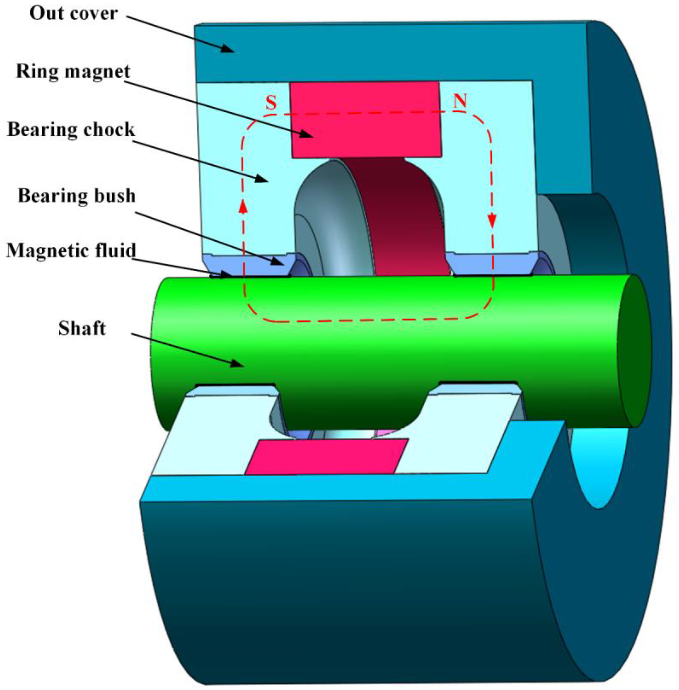
2.3. Design of the Magnetic Fluid Lubricated Bearing Mechanism

The magnetic fluid lubricated bearing structure shown in Figure 3 has been designed on the basis that the discrete magnetic fields generated by the permanent magnets are capable of creating a magnetic circuit in the bearing structure. The outer end cap shown is made of non–magnetic aluminium alloy, the bearing housing, shank and spindle are made of mild steel with good magnetic conductivity. In terms of mechanical hardness they are soft steel. The magnetic field is provided by a permanent magnet ring of material N35 type NdFeB, whose basic parameters are shown in Table 2. Under the action of the permanent magnet ring, the magnetic field forms a magnetic circuit in the bearing structure. The red dashed box and arrows in the diagram indicate the magnetic circuit and the direction of the magnetic field, respectively. The magnetic field is emitted from the permanent magnet ring and passes through the bearing housing, the shaft tile, the main shaft, the shaft tile, the bearing housing and finally back to the permanent magnet ring.

3. Results and Discussion

3.1. Magnetic Fluid Lubrication Viscosity Characteristics

The Roelands [10,14] viscosity equation is often used when studying fluid viscosity, where temperature and pressure are the environmental factors that must be considered:
η t ( T , P ) = η 0 e x p { ( l n η 0 + 9.67 ) [ ( 1 + 5.1 × 10 9 P ) z × ( T 138 T 0 138 ) S 0 1 ] }
T 0 is the initial temperature in K, η 0 is the viscosity at T 0 and zero pressure, z and S 0 are the dimensionless viscous pressure coefficient and the dimensionless viscous temperature coefficient, respectively, generally taken as 0.1~1.5.
The application of Equation (2) requires the following:
  • The volume force and inertial force of the magnetic fluid are negligible;
  • The radius of the journal and bearing is much larger than the film thickness;
  • No-slip phenomenon at the magnetic fluid lubrication interface;
  • The lubrication film does not change along the radial pressure.
For magnetic fluids with a certain volume fraction of magnetic particles, when the magnetic particle volume fraction ϕ > 2%, the coefficient of magnetic fluid dynamic viscosity can be expressed using the Einstein formula modified by Rosensweig [24,25]:
η f 0 η c = 1 1 + 2.5 ϕ 1.55 ϕ 2
When considering the thickness of the surfactant coating on the magnetic particles, it is equivalent to increasing the radius of the magnetic particles, and the radius of the magnetic particles coated with the surfactant is a (1 + c/rp) times the radius of the pure magnetic particles, then the volume fraction is (1 + c/rp)3 times. The Einstein viscosity of the surfactant coated magnetic particles is modified to:
η f 0 η c = 1 1 + 2.5 ( 1 + c r p ) 3 ϕ 1.55 ( 1 + c r p ) 6 ϕ 2
where η f 0 is the magnetic fluid viscosity coefficient in the absence of a magnetic field, η c is the base carrier fluid kinetic viscosity coefficient, ϕ is the magnetic particle volume fraction, c is the surfactant thickness, rp is the average radius of the magnetic particle surfactant together, the main technical parameters of the magnetic fluid are shown in Table 3, then the magnetic fluid viscosity expression in the absence of a magnetic field is:
η t 0 ( T , P ) = 1 1 + 2.5 ( 1 + c r p ) 3 ϕ 1.55 ( 1 + c r p ) 6 ϕ 2 η 0 × e x p { ( l n η 0 + 9.67 ) [ ( 1 + 5.1 × 10 9 P ) z × ( T 138 T 0 138 ) S 0 1 ] }
Equation (5) was calculated using MATLAB to obtain the temperature and pressure dependence of the viscosity of the magnetic fluid lubrication film without the action of a magnetic field as shown in Figure 4. As can be seen from the Figure 4, the viscosity of the magnetic fluid decreases exponentially with increasing temperature and increases linearly with increasing pressure. The main reason for this is that the viscosity of the fluid depends mainly on its intermolecular internal friction, and the resistance to the flow of the magnetic fluid is mainly due to the relative friction between its internal molecules and between the nanoparticles. As the temperature increases, the molecular and magnetic nanoparticle motion within the magnetic fluid increases, the relative distance between the molecules and particles increases, the internal friction decreases and the viscosity of the magnetic fluid decreases. The pressure increases, the magnetic fluid is compressed, the relative distance between the molecules and particles decreases, the internal friction increases and the viscosity of the magnetic fluid increases.
Figure 5 shows the viscosity versus pressure of a magnetic fluid at different temperatures without the effect of a magnetic field. From Figure 5, it can be seen that the viscosity of the magnetic fluid decreases significantly at increasing temperatures. As the pressure increases, the viscosity of the magnetic fluid at 20 °C and 40 °C has a clear tendency to rise, while at 60 °C and 80 °C the viscosity of the magnetic fluid does not tend to rise, and at 100 °C the viscosity of the magnetic fluid barely rises, remaining at 0.2–0.3 Pa·s.
Under the action of the applied magnetic field, the magnetic particles in the magnetic fluid are arranged into a chain structure with the same direction as the magnetic field strength by the magnetic moment, and its viscosity is greater than that of the absence of magnetic field strength. The modified equation for the viscosity of the magnetic fluid under the action of an applied magnetic field is:
η h ( T , P , H ) = ( η + Δ η h ( H ) ) k 1
where η is the magnetic fluid viscosity without magnetic field, Δ η h is the magnetic fluid viscosity increment with magnetic field, both in Pa·s, k1 is the ratio of experimental viscosity increment to theoretical viscosity increment, generally taken as 0.5 to 3. For ease of calculation, the k1 is 1.
According to the rotational viscosity theory of Shliomis [26,27] and Langevin’s theory, the relationship between the incremental viscosity Δ η h of the magnetic fluid and the viscosity of the base carrier fluid is given by:
Δ η h η t = 1.5 1 ϕ + 3 k 0 T 2 π r p 3 μ 0 ( μ r 1 ) H 2
where k0 is the Boltzmann constant with a value of 1.380649 × 10⁻²³, μ0 is the vacuum permeability, μr is the relative permeability, and H is the magnetic field strength in A/m. The magnetic induction strength B and the magnetic field strength H satisfy:
B = μ r H
The expression for the viscosity of a magnetic fluid under the action of a magnetic field is obtained by combining Equations (5)–(8):
η b ( T , P , B ) = η 0 e x p { ( l n η 0 + 9.67 ) [ ( 1 + 5.1 × 10 9 P ) z × ( T 138 T 0 138 ) S 0 1 ] } × [ 1 1 + 2.5 ( 1 + c r p ) 3 ϕ 1.55 ( 1 + c r p ) 6 ϕ 2 + 1.5 k 1 1 ϕ + 3 k 0 T μ r 2 2 π r p 3 μ 0 ( μ r 1 ) B 2 ]
Given a magnetic fluid pressure of 5 MPa, Equation (9) was calculated using MATLAB to obtain the relationship between the viscosity of the magnetic fluid lubrication film under the action of a magnetic field and the variation in temperature and magnetic field as shown in Figure 6. As can be seen in Figure 6, the viscosity of the magnetic fluid gradually increases with increasing magnetic induction, and the growth trend is similar to the magnetization curve, and the viscosity of the magnetic fluid stabilizes when the magnetic induction is greater than 0.4 T. This also indicates that the saturation magnetization strength of this magnetic fluid is around 0.4 T. Under the action of the magnetic field, the magnetic particles within the magnetic fluid are arranged in a chain–like structure along the magnetic field direction by the magnetic moment, which increases the resistance to flow, the viscosity of the magnetic fluid increases and the load–bearing capacity increases [28,29].
Figure 7 shows the variation in magnetic fluid viscosity with magnetic field at different temperatures. As can be seen from the graph, the viscosity of the magnetic fluid is two to three times higher when the magnetic induction is 0.5 T than when there is no magnetic field, and at a temperature of 100 °C, the viscosity of the magnetic fluid can be maintained at 0.5 T at 60 °C without a magnetic field. This suggests that an applied magnetic field can alleviate the poor lubrication of magnetic fluids at temperatures too high to allow for low viscosity. A wider range of service temperatures can be achieved by applying a magnetic field to the magnetic fluid [30].

3.2. Flow Field Analysis of Magneto–Fluid Lubricated Bearings

Given an oil film pressure of 5 MPa in the bearing, a spindle speed of 5000 rpm, an ambient temperature of 20 °C and four different eccentricity rates (0.2, 0.4, 0.6 and 0.8), the oil film pressure and temperature distributions were calculated using Ansys software. Set the grid to Sweet and Type to Element Size. When the eccentricity is 0.8, the minimum film thickness is 0.05 mm, and to ensure that there are two or three layers of mesh at the minimum film thickness, set the Sweet Element Size to 0.02 mm. Set Element Order to Linear and Element Size to 0.05 mm. Set the maximum energy residual value to 10−6 and the number of iteration steps to 500. The magnetic fluid as a non-Newtonian fluid, the Equation (9) is compiled into the viscosity formula of the UDF as the magnetic fluid, the magnetic field strength is set to 0.4 T.
Use an eccentricity of 0.2 as an experimental example, set the Sweet Element Size to 0.015 mm and 0.01 mm as the experimental group, and then set 0.02 mm as the control group for mesh convergence experiments. Take the position of the convergence wedge 3 mm away from the minimum film thickness point as the analysis object. Let the pressure of the experimental group be P and the pressure of the control group to be P0, then the error rate ε is:
ε = | P P 0 | P 0 × 100 %
The following Figure 8 shows the experimental results. It can be seen from the Figure 8 that the maximum error rate does not exceed 3%, indicating that the results obtained by the Sweet Element Size to 0.02 mm are valid.
Figure 9 shows the oil film pressure distribution of magnetic fluid bearings with different eccentricity. From the figure it can be seen that the oil film is separated into a high-pressure zone and a low-pressure zone in the minimum oil film thickness area, the high-pressure zone corresponds to a converging wedge, the low-pressure zone corresponds to a diverging wedge, and the high- pressure and low-pressure distribution is approximately symmetrical. The maximum pressure of the converging wedge is 5.24 MPa and the minimum pressure of the diverging wedge is 4.76 MPa when the eccentricity is 0.2. As the eccentricity increases, the pressure of the converging wedge becomes higher and the pressure of the diverging wedge becomes lower, the pressure difference between high and low pressure gradually increases, and the distribution range of high and low pressure gradually concentrates towards the minimum oil film thickness area, the highest pressure of the converging wedge reaches 8 MPa when the eccentricity is 0.8, and the lowest pressure of the diverging wedge is 2 MPa. This is because as the eccentricity increases, the size of the converging wedge inlet of the magnetic fluid lubricant film increases and the size of the outlet decreases, accumulating more and more magnetic fluid near the outlet of the converging wedge and increasing pressure; the size of the diverging wedge inlet decreases and the size of the outlet increases, with less and less magnetic fluid near the diverging wedge inlet and decreasing pressure. Thus, the magnetic fluid lubricating oil film has a strong wedge effect, and the oil film carrying capacity is increased, leaving the journal in a relatively balanced position [31].
Figure 10 gives the oil film temperature distribution of magnetic fluid bearings with different eccentricity. As can be seen from the figure, the high temperature zone is mainly distributed in the middle of the oil film axis and around the minimum oil film thickness. At a low eccentricity (0.2), the oil film temperature distribution is more uniform, with the minimum oil film thickness area and a large area in the middle of the oil film axial direction being between 55 °C and 65 °C. As the eccentricity increases, the oil film temperature gradually increases and the high temperature zone gradually concentrates towards the middle of the oil film axial direction and the minimum oil film thickness zone. At a higher eccentricity (0.8), the oil film temperature distribution level is obvious, with the minimum oil film thickness area and a small area in the middle of the oil film axial range between 90 °C and 110 °C. The oil film temperature gradually decreases from above 100 °C in the middle of the axial range to below 30 °C on both sides. This is mainly due to the fact that the magnetic fluid dissipates heat by conduction from the middle of the axial direction to the sides. It should be noted that when the eccentricity is large, the volume of the magnetic fluid at the minimum oil film thickness is small and the heat dissipation effect is poor; the volume of the magnetic fluid at the maximum oil film thickness is large and the heat dissipation effective. It should be noted that the temperature distribution between the converging and diverging wedges at the minimum film thickness is not the same on both sides, but further research is required to obtain the exact temperature difference.
To further investigate the minimum oil film thickness and its surrounding area temperature distribution, Figure 11 shows the minimum oil film thickness area and the temperature of the converging and diverging wedge areas (shown in Figure 10) at a symmetrical distance of 3 mm from each other with respect to axial position. As can be seen from the diagram, the magnetic fluid in the axial position shows a trend of high in the middle and low on both sides due to the heat dissipation effect region. At an eccentricity of 0.2, the maximum temperature in the area is maintained at a stable 63 °C. As the eccentricity increases, the thickness at the minimum oil film thickness becomes smaller and smaller, the magnetic fluid volume is less, the heat dissipation effect is poor and the maximum temperature becomes higher and higher, and at an eccentricity of 0.8, the maximum temperature in the area reaches 125 °C. It should be noted that the temperature of the diverging wedge at the axial center is higher than that of the converging wedge at all eccentricities, as can be easily seen in Figure 10, and the difference increases with increasing eccentricity. This is mainly because the convection heat dissipation, the magnetic fluid enters from the large port to the small port in the converging wedge, and the pressure gradually increases and the temperature gradually increases. The temperature rise of the magnetic fluid is the largest at the minimum oil film thickness, and the temperature rise decreases after entering the diverging wedge, but the temperature still rises slightly, so the temperature of the magnetic fluid of the diverging wedge is higher than that of the converging wedge, and it converges with the increase of eccentricity. The difference between the inlet and outlet of the wedge is larger, and the temperature of the magnetic fluid rises faster. The temperature of the magnetic fluid at the divergent wedge is higher than that of the convergent wedge [32]. It can be seen that the temperature of the magnetic fluid drops particularly fast on both sides of the axial side of the evanescent wedge, mainly because the magnetic fluid is in the small mouth of the evanescent wedge and out of the large mouth, the flow rate is reduced, and the magnetic fluid has a certain viscosity, the flow rate of the magnetic fluid on both sides of the axial side is smaller [33], the heat dissipation time is longer and the temperature is particularly low.
The reasons for cavitation are mainly two factors of temperature and pressure. The boiling point of glycerin is 290 °C, and the maximum temperature of the magnetic fluid temperature distribution diagram is only 130 °C, which is much lower than the boiling point of glycerin. Temperature cannot make bears create cavities. Cavitation occurs when the magnetic fluid pressure is very small, generally below one atmosphere. However, it can be seen from the magnetic fluid pressure distribution diagram that its minimum pressure is 2 MPa, which is much larger than one atmospheric pressure. Therefore, the pressure factor cannot cause cavities. The higher the degree of cavitation of the device, the worse the stability, the faster the vibration speed and the higher the frequency [34]. Since there is no cavitation in the bearing, the vibration speed and amplitude are very small, and the stability is high.

3.3. Magnetic Field Analysis of Magnetic Fluid Lubricated Bearings

Figure 12 shows the magnetic field distribution along the axial section of the bearing with different eccentricities. It can be seen from Figure 11 that the strong magnetic field strength is mainly concentrated in the inner side of the bearing gap and the main shaft connected with it. This is mainly due to the boundary effect of the magnetic field, and the conduction converges when passing through the main axis. Without eccentricity, the magnetic field distribution on the main shaft section is smaller than that with eccentricity. And as the eccentricity increases, the magnetic field strength is stronger. This is because the larger the eccentricity, the smaller the gap between the bearing inner ring and the main shaft, the weaker the magnetic resistance strength, and the stronger the magnetic field strength. However, the magnetic field intensity distribution in the bearing gap cannot be seen from Figure 12, and further research is required.
The exact location of the solving surface and the solving domain of the magneto–fluid bearing is shown in Figure 13. The magnetic field in the solution domain of the magnetic fluid bearing is calculated using Ansys software for four different eccentricities, and the distribution of the magnetic field in the solution domain of the magnetic fluid bearing is shown in Figure 14. From the figure it can be seen that the magnetic field is stronger in the magnetic fluid bearing shaft and journal clearance, and in the minimum oil film thickness zone magnetic induction intensity is the largest, from the minimum to the maximum oil film thickness zone, magnetic induction intensity gradually decreases. When the eccentricity is 0.2, the magnetic induction intensity in the minimum oil film thickness area is 0.5 T~0.55 T, and the magnetic induction intensity in the maximum oil film thickness area is 0.4 T~0.45 T, and the difference between the two is not significant. With the increase in eccentricity, the magnetic induction intensity in the minimum oil film thickness area is gradually enhanced, and the magnetic induction intensity in the maximum oil film thickness area is basically unchanged, and the difference between the two gradually increases. When the eccentricity is 0.8, the magnetic induction intensity of the minimum oil film thickness area has reached 1.5 T. At this time, a large number of magnetic particles gather in the minimum oil film thickness area and form a chain along the magnetic field direction to improve the bearing capacity of the minimum oil film thickness area. As the eccentricity increases, the temperature of the magnetic fluid increases, causing its viscosity to decrease sharply, and the temperature is highest at the smallest film thickness.
Due to the high pressure on the magnetic fluid during the simulation process, especially in the case of a large eccentricity. Although the strength of the applied magnetic field is applied, it is inevitable that local elastic deformation will occur, reducing its viscosity, making the lubrication effect of the magnetic fluid worse, and increasing the wear of friction devices. However, compared with ordinary lubricants, under such harsh working conditions, the magnetic fluid when the magnetic field is applied still has a better lubrication effect. By adjusting the strength of the magnetic field, the viscosity of the magnetic fluid is maintained at a high level, maintaining its good lubrication effect, and it is expected to minimize the wear of the friction device.
Although the eccentricity increases and the magnetic fluid pressure increases, its viscosity increases, but its elevation is limited. It can be seen from the magnetic field distribution map that the eccentricity increases, the magnetic field strength of the magnetic fluid lubrication zone increases, and the magnetic field strength is strongest at the minimum film thickness. This effectively alleviates the effect of the magnetic fluid at the minimum film thickness due to the harsh working conditions of the temperature, resulting in a sharp decrease in viscosity and poor lubrication effect. From this reference [25], the experimental data of viscosity with temperature and magnetic field strength is similar to the simulation data of this paper. According to the theory of hydrodynamic lubrication, the pressure distribution and temperature distribution trend of the bearing can be determined to be completely correct.
As the eccentricity of the magnetic fluid bearing increases, the temperature of the minimum oil film thickness zone gradually increases and the viscosity of the magnetic fluid decreases, but the minimum oil film thickness zone presents a higher magnetic induction strength, which can improve the viscosity of the magnetic fluid to a certain extent and enhance the lubrication effect of the magnetic fluid in the minimum oil film thickness zone [35] to achieve long–term reliable lubrication under wide temperature range operating conditions. According to the magnetic fluid pressure resistance calculation equation:
Δ P = M s B max
where M s is the saturation magnetization strength of the magnetic fluid and B max is the maximum value of magnetic induction in the bearing gap. From the Equation (11) can be seen that the magnetic fluid bearing has a certain pressure resistance, and the greater the eccentricity the stronger the pressure resistance, which is compared with the traditional sealed bearing using labyrinth seal and honeycomb seal structure, a simpler construction with magnetic fluid bearing seals.

4. Conclusions

In order to solve the bearing in the service process due to high temperatures (≥80 °C), to reduce the viscosity of lubricating oil caused by lubrication failure, based on the magnetic fluid viscous temperature, viscous pressure and magnetic viscosity characteristics, the design of magnetic fluid lubrication bearing structure, and to discuss the pressure, temperature and magnetic field distribution of its bearings, the following conclusions were drawn:
(1)
The viscosity of the magnetic fluid decreases exponentially with increasing temperature, increases linearly with increasing pressure, and increases with increasing field strength; the viscosity of the magnetic fluid rises first and then stabilizes, with a similar upward trend to the magnetization curve.
(2)
The oil film pressure distribution is separated by the minimum oil film thickness area into two approximately symmetrical high-pressure and low-pressure areas, with the bearing eccentricity increases, the pressure difference between high and low pressure gradually increases, and the high-pressure and low-pressure areas are gradually concentrated towards the minimum oil film thickness area, the oil film wedge effect is enhanced.
(3)
The oil film high temperature zone is mainly distributed in the middle of the axial region and around the minimum oil film thickness area; with the bearing eccentricity increases, the oil film high temperature zone temperature increases and concentrates around the middle of the axial region and the minimum oil film thickness area, the heat dissipation method is mainly heat conduction and convection heat dissipation.
(4)
The magnetic field of magnetic fluid bearing is distributed in the clearance between the shaft and the journal, and when the eccentricity of the bearing is increased, the magnetic induction intensity in the maximum oil film thickness area remains the same, while the magnetic induction intensity in the minimum oil film thickness area is the strongest. In addition, the magnetic fluid bearing has a certain sealing pressure resistance; high eccentricity of the magnetic fluid bearing sealing performance is better.
The results of the feasibility of using magnetic fluids to lubricate sliding bearings with different eccentricities are presented. Due to the unique viscous–temperature, viscous–pressure and magnetic–viscous properties of magnetic fluids, active lubrication can be achieved under an applied magnetic field, resulting in reliable service over a wide temperature range. However, the magnetic flux density required for bearing clearance varies under different operating conditions, and the magnetic field must be adjustable to achieve reliable service over a wide temperature range. The principle of electromagnetic induction can be relied upon to turn permanent magnets into a magnetic field generating device with adjustable magnetic field strength, and the study of magnetic flux density required for bearing lubrication under different operating conditions is of practical significance for the application of magnetic fluids in bearings.

Author Contributions

Conceptualization, A.W. and J.Y.; methodology, J.P.; software, H.W.; validation, A.W., J.Y. and H.W.; formal analysis, A.W.; investigation, A.W.; resources, A.W.; data curation, A.W.; writing—original draft preparation, A.W.; writing—review and editing, A.W.; visualization, J.P.; supervision, J.P.; project administration, J.P.; funding acquisition, J.P. All authors have read and agreed to the published version of the manuscript.

Funding

This research was funded by the National Natural Science Foundation of China, grant number 52005004 and Open Project of Key Laboratory of Helicopter Transmission Technology, Nanjing University of Aeronautics and Astronautics, grant number HTL-O-20G09.

Institutional Review Board Statement

Not applicable.

Informed Consent Statement

Not applicable.

Data Availability Statement

Not applicable.

Conflicts of Interest

The authors declare no conflict of interest.

References

  1. Li, J.; Dai, Q.; Huang, W.; Wang, X. Feasibility study of magnetic fluid support and lubrication behaviors on micro magnet arrays. Tribol. Int. 2020, 150, 106407. [Google Scholar] [CrossRef]
  2. Shi, X.; Huang, W.; Wang, X. Ionic liquids–based magnetic nanofluids as lubricants. Lubr. Sci. 2018, 30, 73–82. [Google Scholar] [CrossRef]
  3. Wang, J.; Zuo, Z.P.; Zhao, Y.; Hou, D.; Li, Z. Preparation and viscosity characteristics of nano–scale magnetic fluid oil–film bearing oil. J. Nanosci. Nanotechnol. 2019, 19, 2688–2694. [Google Scholar] [CrossRef]
  4. Khalil, A.; Nabhani, M.; Khlifi, M.E. Rotational viscosity effect on the stability of finite journal bearings lubricated by ferrofluids. J. Braz. Soc. Mech. Sci. 2021, 43, 548. [Google Scholar]
  5. Li, K.; Dai, J.; Chang, H.; Huang, J.; Shi, J. Review of magnetorheological materials application. J. Detect. Control 2019, 41, 6–14. [Google Scholar]
  6. Kumar, J.S.; Paul, P.S.; Raghunathan, G.; Alex, D.G. A review of challenges and solutions in the preparation and use of magnetorheological fluids. Int. J. Mech. Mater. Eng. 2019, 14, 13. [Google Scholar] [CrossRef]
  7. Tian, Z.; Hou, Y.; Wang, N. Study on temperature properties of magnetorheological transmission device. Chin. J. Sci. Instrum. 2012, 33, 596–601. [Google Scholar]
  8. Shah, R.C.; Shah, R.B. Static and dynamic performances of ferrofluid lubricated long journal bearing. Z. Für Nat. A 2021, 76, 493–506. [Google Scholar] [CrossRef]
  9. Zapoměl, J.; Ferfecki, P. A new concept of a hydrodynamic bearing lubricated by composite magnetic fluid for controlling the bearing load capacity. Mech. Syst. Signal Pract. 2022, 168, 108678. [Google Scholar] [CrossRef]
  10. Shah, R.C. Ferrofluid lubrication of porous–rough circular squeeze film bearings. Eur. Phys. J. Plus 2022, 137, 190. [Google Scholar] [CrossRef]
  11. Wang, X.; Lu, W.; LI, H.; Meng, G. A magnetorheological fluid lubricated floating ring bearing and its application to rotor vibration control. J. Vib. Shock 2017, 36, 18–24. [Google Scholar]
  12. Patel, J.R.; Deheri, G. Viscosity variation effect on the magnetic fluid lubrication of a short bearing. J. Serb. Soc. Comput. Mech. 2019, 13, 56–66. [Google Scholar] [CrossRef]
  13. Urreta, H.; Aguirre, G.; Kuzhir, P.; Lopez de Lacalle, L.N. Actively lubricated hybrid journal bearings based on magnetic fluids for high–precision spindles of machine tools. J. Intell. Mat. Syst. Struct. 2019, 30, 2257–2271. [Google Scholar] [CrossRef] [Green Version]
  14. Patel, N.S.; Vakharia, D.; Deheri, G. Hydrodynamic journal bearing lubricated with a ferrofluid. Ind. Lubr. Tribol. 2017, 69, 754–760. [Google Scholar] [CrossRef]
  15. Quinci, F.; Litwin, W.; Wodtke, M.; Nieuwendijk, R. A comparative performance assessment of a hydrodynamic journal bearing lubricated with oil and magnetorheological fluid. Tribol. Int. 2021, 162, 107143. [Google Scholar] [CrossRef]
  16. Kataria, R.C.; Patel, D.A. Study of double porous layered slider bearing with various designed stator under the effects of slip and squeeze velocity using magnetic fluid lubricant. Am. J. Appl. Math. Stat. 2020, 8, 43–51. [Google Scholar]
  17. Hu, Z.; Dai, Q.; Huang, W.; Wang, X. Liquid–gas support and lubrication based on a ferrofluid seal. J. Phys. D Appl. Phys. 2020, 53, 025002. [Google Scholar] [CrossRef]
  18. Li, J.; Dai, Q.; Huang, W.; Wang, X. Magnetic fluid support and lubrication properties based on arrayed magnets. Tribology 2022, 42, 275–282. [Google Scholar]
  19. Xie, X.; Dai, Q.; Huang, W.; Wang, X. Supporting capacity of a ferrofluid ring bearing. J. Phys. D Appl. Phys. 2021, 54, 175004. [Google Scholar] [CrossRef]
  20. Xu, H.; Dai, Q.; Huang, W.; Wang, X. The supporting capacity of ferrofluids bearing: From the liquid ring to droplet. J. Magn. Magn. Mater. 2022, 552, 169212. [Google Scholar] [CrossRef]
  21. Pei, P.; Peng, Y. Microstructural evolution and aggregation kinetics of magnetorheological suspensions based on molecular dynamics simulations. Mat. R. 2021, 35, 12001–12007. [Google Scholar]
  22. Pei, P.; Peng, Y. Constitutive modeling of magnetorheological fluids: A review. J. Magn. Magn. Mater. 2022, 550, 169076. [Google Scholar] [CrossRef]
  23. Shen, Y.; Hua, D.; Liu, X.; Li, W.; Grzegorz, K.; Li, Z. Visualizing rheological mechanism of magnetorheological fluids. Smart Mater. Struct. 2022, 31, 025027. [Google Scholar] [CrossRef]
  24. Shah, R.C.; Patel, D.B. On the ferrofluid lubricated exponential squeeze film–bearings. Z. Für Nat. A 2021, 76, 209–215. [Google Scholar] [CrossRef]
  25. Wang, J.; Kang, J.; Zhang, Y.; Huang, X. Viscosity monitoring and control on oil-film bearing lubrication with ferrofluids. Tribol. Int. 2014, 75, 61–68. [Google Scholar]
  26. Munshi, M.M.; Patel, A.R.; Deheri, G.M. Lubrication of rough short bearing on shliomis model by ferrofluid considering viscosity variation effect. Int. J. Math. Eng. Manag. Sci. 2019, 4, 982–997. [Google Scholar] [CrossRef]
  27. Munshi, M.M.; Patel, A.R.; Deheri, G.M. Numerical modelling of shliomis model based ferrofluid lubrication performance in rough short bearing. J. Theor. Appl. Mech. 2019, 57, 923–934. [Google Scholar] [CrossRef]
  28. Jian, G.; Wang, Y.; Yu, X.; Li, Y.; Luo, H. Coupling on ferrofluid lubrication and dynamics of gear system. Tribology 2021, 41, 325–333. [Google Scholar]
  29. Li, Y.; Luo, Y.; Luo, J.; Wang, Y.; Ren, H.; Jiang, L.; Qiu, J.; Su, Z.; Fang, Q. Study on the influence of temperature–magnetic field coupling on the mechanical properties of magnetorheological fluids. Phys. Status Solidi–R. 2022, 16, 2100476. [Google Scholar] [CrossRef]
  30. Zaripov, A.K.; Ubaidi, A. Dependence of the viscosity of magnetic fluids on the concentration of magnetic particles, temperature, and a magnetic field. Russ. J. Phys. Chem. A 2021, 95, 2141–2147. [Google Scholar] [CrossRef]
  31. Widodo, P.J.; Budiana, E.P.; Ubaidillah, U.; Imaduddin, F. Magnetically–induced pressure generation in magnetorheological fluids under the influence of magnetic fields. Appl. Sci. 2021, 11, 9807. [Google Scholar] [CrossRef]
  32. Iwamoto, Y.; Nakasumi, H.; Ido, Y.; Niu, X.D.; Qiu, J.H.; Xiong, K.; Ji, H.L. Heat transfer of temperature–sensitive magnetic fluids around single heating pipe. Int. J. Appl. Electrom. Mech. 2020, 64, 1039–1046. [Google Scholar] [CrossRef]
  33. Kumar, S.; Sehgal, R.; Wani, M.F.; Sharma, M.D. Stabilization and tribological properties of magnetorheological (MR) fluids: A review. J. Magn. Magn. Mater. 2021, 538, 168295. [Google Scholar] [CrossRef]
  34. Zhu, G.; Li, K.; Feng, J.; Luo, X. Effects of cavitation on pressure fluctuation of draft tube and runner vibration in a Kaplan turbine. Trans. Chin. Soc. Agr. Eng. 2021, 37, 40–49. [Google Scholar]
  35. Li, Z.; Li, D.; Dong, J.; Cui, H.; Yao, J. Study of temperature influence on the rheological behavior of magnetic fluids. J. Magn. Magn. Mater. 2022, 545, 168757. [Google Scholar] [CrossRef]
Figure 1. Distribution of oil pressure in radial plain bearings.
Applsci 12 07051 g001
Figure 2. Distribution of magnetic particles with and without a magnetic field: (a) without magnetic field; (b) with magnetic field.
Applsci 12 07051 g002
Figure 3. Magnetic fluid lubricated bearing structure.
Applsci 12 07051 g003
Figure 4. Magnetic fluid lubrication film viscosity relationship.
Applsci 12 07051 g004
Figure 5. Magnetic fluid lubrication film viscosity–temperature and viscosity–pressure characteristics.
Applsci 12 07051 g005
Figure 6. Magnetic adhesion properties of magnetic fluid lubrication film.
Applsci 12 07051 g006
Figure 7. Viscosity relationship of magnetic fluid lubrication film under magnetic field.
Applsci 12 07051 g007
Figure 8. Mesh convergence analysis experimental results.
Applsci 12 07051 g008
Figure 9. Magnetic fluid lubrication film pressure distribution.
Applsci 12 07051 g009
Figure 10. Temperature distribution of magnetic fluid lubrication film.
Applsci 12 07051 g010
Figure 11. Temperature of magnetic fluid lubrication film. (a) ε = 0.2; (b) ε = 0.4; (c) ε = 0.6; (d) ε = 0.8.
Applsci 12 07051 g011
Figure 12. Magnetic field distribution along the axial section of the bearing.
Applsci 12 07051 g012
Figure 13. Magnetic field solution surface and solution domain.
Applsci 12 07051 g013
Figure 14. Magnetic field distribution of magnetic fluid lubrication film.
Applsci 12 07051 g014
Table 1. Basic parameters of the structure of bearing friction pairs.
Shaft Diameter (D/mm)Bore of the Shaft Shank (d/mm)Shaft Shank Width (B/mm)Eccentricity ( ε )
1616.05100.2, 0.4, 0.6, 0.8
Table 2. Basic parameters of permanent magnet rings.
Outer Diameter (D/mm)Inner Diameter (d/mm)Width (B/mm)Orthopaedic Force (A/m)Operating Temperature (°C)
57411687,000≤100
Table 3. Main technical parameters of the magnetic fluid.
Particle Volume Fraction ( ϕ ) Surfactant Thickness
(c/nm)
Magnetic Particle Diameter (d/nm)Base Carrier Fluid Viscosity ( η f 0 /Pa·s)
30%2101.5
Publisher’s Note: MDPI stays neutral with regard to jurisdictional claims in published maps and institutional affiliations.

