Abstract
This paper presents a control structure integrating guidance and control loops for tail-controlled missile systems. Motivated by the fact that common tail-controlled missiles involve non-minimum phase dynamics, the proposed controller is designed to prevent the internal dynamics from diverging, as well as achieving homing against the intended target. To minimize the miss distance at the end of homing, we derive a formulation of a zero-effort-miss using engagement kinematics that contain the rotating dynamics of the missile, which is different from existing approaches. Subsequently, to nullify the zero-effort-miss, a nonlinear controller is designed based on the Lyapunov stability theory. Since the derived controller has a similar structure to the conventional three-loop topology that has been utilized for various tail-controlled flight systems, it is expected that the proposed method can be applied to the actual system from a practical point of view. Numerical simulation results also show that the proposed method achieves target interception while possessing stable internal dynamics.
1. Introduction
General fixed-wing aircraft perform maneuvers in a specific direction by generating aerodynamic forces based on attitude control. Specifically, in the case of aerodynamic-driven missiles, tail or canard wings are used to produce the angle-of-attack for generating the required acceleration. Since canard wings are mounted near the missile warhead, the lift by the control input of a canard-controlled missile is in the same direction as the main maneuver by the angle-of-attack. Based on this property, canard control is generally considered a method to easily secure flight stability. However, due to the short distance from the center of gravity, the maximum magnitude of the moment that can be generated from the canard is limited in comparison with the tail-controlled configuration.
On the contrary, a tail-controlled missile can yield a greater moment than a canard-controlled missile with the same magnitude of the control input since tail wings are commonly located far away from the missile’s center of mass. However, tail control leads to a non-minimum phase problem as the direction of the aerodynamic force produced by the tail fin is opposite to the direction of the main maneuver produced by the angle-of-attack of the fuselage. For these reasons, the existing studies that aim at developing autopilot for tail-controlled missiles have focused on dealing with the non-minimum phase problem [1,2,3,4,5,6].
The study presented in [1] applied plant inversion techniques to develop a controller for the angle-of-attack. To avoid difficulties in dealing with non-minimum phase dynamics, the outer loop that converts the acceleration command into the angle-of-attack signal is combined. The work in [2] developed nonlinear autopilot based on feedback linearization methods with the use of time-scale separation techniques and redefinitions of the system outputs. The autopilot designed by [3] used augmented lateral acceleration to overcome stabilization difficulties in non-minimum phase dynamics, and the optimal control theory has been applied with the conventional three-loop autopilot topology in [4]. A classical proportional-integral controller has been used to configure the cascaded control structure able to overcome the non-minimum phase problem in [5], and various three-loop topologies have been investigated among comparisons of linear and nonlinear approaches in [6].
As in the studies described above, it is common for the autopilot loop to be designed separately from the guidance loop. In this configuration, the autopilot loop is structured to track the desired acceleration command generated from the guidance loop, such as in [7,8]. This separate loop configuration has advantages, making both the design and analysis for each loop easier. However, rapid changes in each loop can incur instability to the other loop because the stability of whole system is not considered concurrently. For such reasons, there have been several approaches to develop an integrated guidance and control loop to enhance the terminal performance.
In the studies of [9,10,11], the dynamics of canard-controlled missiles are considered for the design of integrated guidance autopilot. Since there is no need to deal with non-minimum phase dynamics, unlike in tail-controlled missiles, these studies have applied various control techniques in a straightforward manner. The integrated guidance autopilot methods presented in [12,13,14] have been designed without close consideration of the non-minimum phase problem because models of dual-controlled missiles have been adopted for such studies. For these reasons, the existing approaches for canard [9,10,11] or dual [12,13,14] controlled missile dynamics cannot be properly adopted for tail-controlled missiles because they do not consider zero-dynamics stability.
In this study, we propose a control configuration that integrates guidance and control loops for tail-controlled missile dynamics. To achieve target interception, we first formulate the zero-effort-miss (ZEM) based on the integrated dynamics considering the rotation of the missile, unlike in separate approaches. Then, the nonlinear control technique is applied to force the ZEM to converge to zero. The proposed integrated controller has a similar structure to the conventional three-loop topology that is known to stabilize the internal dynamics of the flight vehicle. Thus, the proposed controller can be applied to various tail-controlled flight dynamics, which is unlike existing integrated methods.
The remainder of this paper consists of the following: Section 2 provides the integrated equation including both the engagement kinematics and flight dynamics, as formulated based on the tail-controlled missile configuration. In Section 3, synthesized control for the integrated guidance and autopilot is designed, and the performance of the proposed controller is demonstrated through numerical simulations in Section 4. Concluding remarks are presented in Section 5.
2. Problem Formulation
Consider the engagement kinematics of a missile M that tries to intercept a target T, as shown in Figure 1. In this figure, denotes the position of each one in the plane. , , and represent the speed, normal acceleration, and flight path angle of each one. Then, the equations of motion of the missile and target are given by
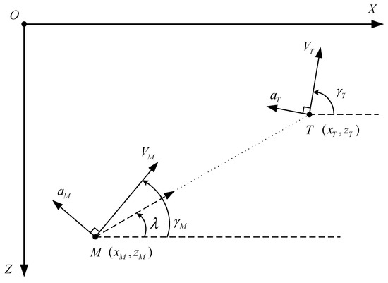
Figure 1.
Two-dimensional engagement geometry for a moving target.
In addition, the relative range r and line-of-sight (LOS) angle between the missile and target are governed by the equations of
where the look angles and are defined as and , respectively. Combining (1)∼(4), we have the linearized kinematics on the initial LOS frame as follows [9]:
where is the guidance state vector given by for the relative range z defined as . The matrices , , and are given by
Herein, the missile acceleration in (5) is produced by the aerodynamic force as , where , m, , and are the lift by the angle-of-attack, mass, angle-of-attack, and tail fin deflection of the missile, respectively. In addition, the short period dynamics of the missile in the plane are given by
where the variable q is the pitch rate of the missile. Q, S, l, and are the dynamic pressure, reference area, reference length, and moment of inertia of the pitch axis, respectively, and , , , , and are the aerodynamic coefficients. Herein, if we design a state feedback controller based on (7) and (8), the controller will be challenging to apply to practical situations due to the angle-of-attack being difficult to measure at high-speed conditions. Thus, in terms of the practical application of the controller, it is more advantageous to use the normal acceleration , obtainable from the INS sensor, as a state variable rather than the angle-of-attack. Using as a state variable, the equations in (7) and (8) can be rewritten as
where is the redefined missile state vector given by and the system matrices and are given by
Combining (5) and (9), we have the integrated equations of the integrated dynamics as
where x is the integrated state vector defined as . The matrices A, B, and C are given by
Note that the integrated dynamics in (11) use the normal acceleration and pitch rate q, of which information is acquirable from the IMU sensor of the missile in real time, as state variables. Therefore, this enables the design of a more practical method than the controller of [9], which requires angle-of-attack information that is difficult to measure directly.
3. Integrated Control for Guidance and Autopilot Synthesis
In this section, we design the integrated guidance autopilot through two subsections. In Section 3.1, we first present ZEM using the dynamics of (11) in which the missile dynamics are included as well as the engagement kinematics, similar to the research in [9]. In Section 3.2, based on the proportional control structure, the autopilot regulating ZEM for homing is developed using the Lyapunov stability theory.
3.1. Zero-Effort-Miss of the Integrated Dynamics
Based on the equations in (11), the state transition matrix of the integrated dynamics is given by
which can be used to obtain the integrated ZEM as
where denotes the first row of the 5-dimensional identity matrix . The remaining time-to-go, defined as , is applied to the controller design using an estimate of
Considering the structure of the matrix A in (12), it is deduced that ZEM in (14) can be rewritten as
where represents the th component of the state transition matrix defined as . In addition, the first and second terms in (16) are related to the guidance variables and can be rewritten as
where the estimation of the time-to-go in (15) is used. Substituting (17) into (16), we have the expression for ZEM as
The proposed ZEM in (18) means the terminal miss distance with the target when the tail fin rate of the missile is maintained at zero. Hence, by stabilizing ZEM at zero, we can achieve target interception while minimizing the terminal rate of the tail fin deflection. To this end, in the next section, we design a controller that can regulate ZEM based on the simple proportional control structure.
3.2. Design of an Integrated Guidance Autopilot via Proportional Control
Taking the time derivative to ZEM, we have
where the scalar functions and are defined as
respectively. From (19), we can present the command for the integrated autopilot guidance as
where is the controller gain, selected as a positive constant. Substituting (21) into (19) leads to
If we consider the Lyapunov candidate function of , then its derivative satisfies that
where Young’s inequality is used. The inequality in (23) implies that ZEM converges into the ball whose radius is given by
if the gain is chosen to satisfy . It can also be seen that the convergence radius in (24) goes to zero as the missile approaches the target. Namely, the command of the tail fin rate in (21) ensures the convergence of ZEM in (18), which means the achievement of the interception against a maneuvering target.
In addition, since the proposed control input in (21) stabilizes the ZEM of the integrated dynamics at zero, the closed-loop stability of the missile dynamics is determined by the zero-input stability governed by (7) and (8) with . To identify the internal stability, let us investigate the dynamics of the angle-of-attack as
where (7) and (8) are used. In the common flight dynamics of fixed-wing aircraft, the coefficient has a positive value to produce lift in the upward direction. In addition, for stability in the longitudinal direction, the coefficients and are designed to have negative values [15]. As a result, the equation in (25) gives proof that is asymptotically stable at zero, which implies that is marginally stable.
The proposed command in (21) can be applied as a form of tail fin command through integration as follows:
which can be rewritten as
where , , , and are the functions of the time-to-go as
Note that the rewritten control command in (27) shows that it consists of feedback loops of guidance variables, normal acceleration, and angular rate with an integrator. As shown in Figure 2, this configuration is similar to a simple guidance and control structure including a well-known three-loop autopilot topology that is proven to stabilize the internal dynamics. Furthermore, since the values of the controller gains required to implement the proposed command are appropriately determined by (28) according to the engagement situation, it is free from gain scheduling, which requires significant effort, unlike the conventional three-loop-based method. Therefore, it is expected that the proposed integrated control method can be easily implemented from a practical point of view.
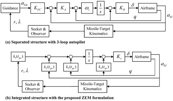
Figure 2.
Guidance and autopilot structures.
4. Numerical Simulation
To demonstrate the proposed guidance and control method, we investigate the performance of the proposed guidance law through numerical simulation using two different missile models: canard-controlled and tail-controlled dynamics, respectively. The dual missile model used in [12] is adopted for the simulation, and the input channel of the tail or canard is ignored to implement the canard- or tail-controlled missile model, respectively. Specifically, the aerodynamic lift and pitch moment of the missile model are governed by
The canard-controlled model is implemented by ignoring the tail fin deflection , and conversely, the tail-controlled model is realized with the canard deflection as zero. The other expressions and specific values of the parameters can be found in [12].
As a means to evaluate the performance of the proposed method, a separate method consisting of the ZEM-based guidance law and Lyapunov-based autopilot is used, as shown in [9].
where is the time constant of the actuator dynamics of the control fin. N and M are the controller gains whose values are selected to be positive.
The ZEM-based guidance law in (31) is structured as well-known proportional navigation guidance and the Lyapunov-based autopilot in (32) is designed to only stabilize the dynamics of at . Now, the performance of the proposed integrated method in (27) can be compared with this separate method consisting of (31) and (32) through the simulation results under two different missile models.
Figure 3 and Figure 4 illustrate the simulation results of both methods under the canard-controlled missile model with the settings given in Table 1. Figure 3a and Figure 4a show that both methods enable the canard-controlled missile to achieve interception against maneuvering targets of g with a miss distance less than 0.3 m. The upper parts of Figure 3b and Figure 4b also provide the results where both methods cause ZEM to converge to zero according to the design purpose.
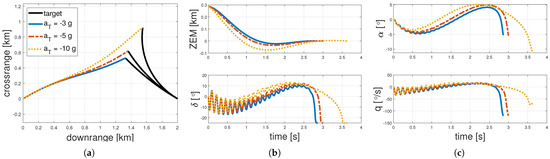
Figure 3.
Simulation results of the separate method under the canard-controlled missile model. (a) Flight trajectories. (b) ZEM and fin deflections. (c) State variables.
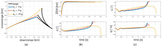
Figure 4.
Simulation results of the integrated method under the canard-controlled missile model. (a) Flight trajectories. (b) ZEM and fin deflections. (c) State variables.

Table 1.
Simulation settings.
However, Figure 3b,c show that the separate method generates fluctuated commands for the canard deflection, causing the state variables to be vibrated. This is because the acceleration controller of the separate method in (32) is configured to only aim at the guidance command, without considering internal dynamics, such as the pitch rate. For reliable autopilot performance, it is necessary to stabilize the rotational dynamics as well as generate the required acceleration. To achieve such requirements, the proposed method in (27) is designed in a three-loop structure that can stabilize the internal dynamics. The results presented in Figure 4b,c show that the proposed integrated method prevents the state variables from fluctuating by generating smoother commands than when using the separate method. In addition, it is shown that all the methods exhibit diverging responses in the vicinity of interception. This is due to the requirement of convergence of the LOS rate defined as (4) in spite of the presence of an unknown target maneuver. That is, unless the missile uses information of the target acceleration, divergence of the command in the vicinity of interception is inevitable.
The results under the tail-controlled missile dynamics, presented in Figure 5 and Figure 6, show large differences between the two methods in stabilizing the internal dynamics. As shown in Figure 5a,b, the separate method fails to intercept the target since it cannot achieve ZEM convergence. Specifically, the lower part of Figure 5b shows that the generated command is saturated for every case, which implies that the separate controller in (32) fails to control the acceleration.
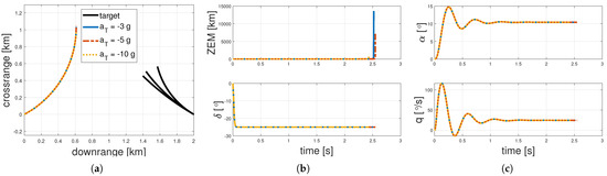
Figure 5.
Simulation results of the separate method under the tail-controlled missile model. (a) Flight trajectories. (b) ZEM and fin deflections. (c) State variables.
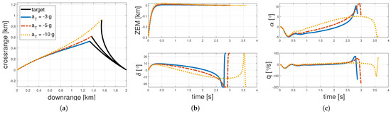
Figure 6.
Simulation results of the integrated method under the tail-controlled missile model. (a) Flight trajectories. (b) ZEM and fin deflections. (c) State variables.
Conversely, Figure 6a,b show that the proposed method fulfils interception by achieving ZEM convergence. Figure 6c also shows that the state variables of the internal dynamics remain stable throughout homing, in spite of the non-minimum phase of the tail-controlled dynamics. Such results imply that the integrated method is more suitable for actual implementation than the separate method, owing to the inclusion of the three-loop-like structure illustrated in Figure 2.
In addition, Figure 7 and Figure 8 show that the proposed method can be implemented in 3-D engagement space. The proposed 2-D planar algorithm is applied by decoupling the 3-D space into longitudinal and lateral planes. As a result, Figure 7a–c and Figure 8a–c exhibit that the proposed integrated method achieves the interception of various maneuvering targets by nullifying the ZEMs in both the longitudinal and lateral directions.
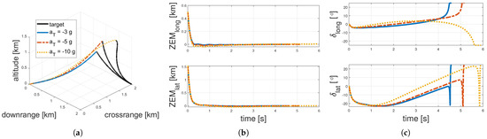
Figure 7.
Three-dimensional simulation results of the integrated method under the canard-controlled missile model. (a) Flight trajectories. (b) ZEM and fin deflections. (c) State variables.
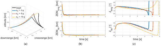
Figure 8.
Three-dimensional simulation results of the integrated method under the tail-controlled missile model. (a) Flight trajectories. (b) ZEM and fin deflections. (c) State variables.
5. Conclusions
In this study, we propose an integrated guidance and control loop structure for tail-controlled missiles. To consider the minimization of the miss distance, we first derive a formulation of the zero-effort-miss using engagement kinematics that contain the rotating dynamics of the missile, unlike existing approaches that construct the guidance and control loops separately. Subsequently, a nonlinear controller was designed to regulate the zero-effort-miss based on the Lyapunov stability theory, which causes the derived autopilot to exhibit a similar structure to the well-known three-loop topology that can prevent the flight dynamics from diverging. Through numerical simulation results, it is demonstrated that the proposed integrated method achieves interception against maneuvering targets, as well as stable dynamics for both canard- and tail-controlled missile dynamics.
Author Contributions
Writing—original draft, H.-G.K.; Writing—review & editing, J.S. All authors have read and agreed to the published version of the manuscript.
Funding
This work was supported by AI-Based Flight Control Research Laboratory funded by Defense Acquisition Program Administration under Grant UD200045CD.
Conflicts of Interest
The authors declare no conflict of interest.
References
- Tahk, M.J.; Briggs, M.M.; Menon, P.K. Applications of plant inversion via state feedback to missile autopilot design. In Proceedings of the 27th IEEE Conference on Decision and Control, Austin, TX, USA, 7–9 December 1988; pp. 730–735. [Google Scholar]
- Menon, P.; Yousefpor, M. Design of nonlinear autopilots for high angle of attack missiles. In Proceedings of the Guidance, Navigation, and Control Conference, San Diego, CA, USA, 29–31 July 1996; p. 3913. [Google Scholar]
- Bruyere, L.; Tsourdos, A.; White, B. Robust augmented lateral acceleration flight control design for a quasi-linear parameter-varying missile. Proc. Inst. Mech. Eng. Part G J. Aerosp. Eng. 2005, 219, 171–181. [Google Scholar] [CrossRef]
- Mracek, C.; Ridgely, D. Missile longitudinal autopilots: Connections between optimal control and classical topologies. In Proceedings of the AIAA Guidance, Navigation, and Control Conference and Exhibit, San Diego, CA, USA, 15–18 August 2005; p. 6381. [Google Scholar]
- Kim, S.H.; Tahk, M.J. Missile acceleration controller design using proportional–integral and non-linear dynamic control design method. Proc. Inst. Mech. Eng. Part G J. Aerosp. Eng. 2012, 226, 882–897. [Google Scholar] [CrossRef]
- Lee, C.H.; Jun, B.E.; Lee, J.I. Connections between linear and nonlinear missile autopilots via three-loop topology. J. Guid. Control Dyn. 2016, 39, 1426–1432. [Google Scholar] [CrossRef]
- Viswanath, D.; Deb, D. Disturbance observer based sliding mode control for proportional navigation guidance. IFAC Proc. Vol. 2012, 45, 163–168. [Google Scholar] [CrossRef]
- Viswanath, D.; Deb, D. A new nonlinear guidance law formulation for proportional navigation guidance. In Proceedings of the 2012 12th International Workshop On Variable Structure Systems, Mumbai, India, 12–14 January 2012; pp. 190–195. [Google Scholar]
- Shima, T.; Idan, M.; Golan, O.M. Sliding-mode control for integrated missile autopilot guidance. J. Guid. Control. Dyn. 2006, 29, 250–260. [Google Scholar] [CrossRef]
- Park, B.G.; Kim, T.H.; Tahk, M.J. Time-delay control for integrated missile guidance and control. Int. J. Aeronaut. Space Sci. 2011, 12, 260–265. [Google Scholar] [CrossRef]
- Panchal, B.; Mate, N.; Talole, S. Continuous-time predictive control-based integrated guidance and control. J. Guid. Control Dyn. 2017, 40, 1579–1595. [Google Scholar] [CrossRef]
- Idan, M.; Shima, T.; Golan, O.M. Integrated sliding mode autopilot-guidance for dual-control missiles. J. Guid. Control Dyn. 2007, 30, 1081–1089. [Google Scholar] [CrossRef]
- Shtessel, Y.B.; Shkolnikov, I.A.; Levant, A. Guidance and control of missile interceptor using second-order sliding modes. IEEE Trans. Aerosp. Electron. Syst. 2009, 45, 110–124. [Google Scholar] [CrossRef]
- Kim, H.G.; Kim, H.J. Integrated guidance and control of dual missiles considering trade-off between input usage and response speed. In Proceedings of the 2013 13th International Conference on Control, Automation and Systems (ICCAS 2013), Gwangju, Korea, 20–23 October 2013; pp. 55–60. [Google Scholar]
- Stevens, B.L.; Lewis, F.L.; Johnson, E.N. Aircraft Control and Simulation: Dynamics, Controls Design, and Autonomous Systems; John Wiley & Sons: Hoboken, NJ, USA, 2015. [Google Scholar]
Publisher’s Note: MDPI stays neutral with regard to jurisdictional claims in published maps and institutional affiliations. |
© 2022 by the authors. Licensee MDPI, Basel, Switzerland. This article is an open access article distributed under the terms and conditions of the Creative Commons Attribution (CC BY) license (https://creativecommons.org/licenses/by/4.0/).