1. Introduction
In recent years, we have observed a change in the way robots are used in the industry. The workspaces of robots and humans are beginning to overlap, which is allowed by the introduction of collaborative robots that are designed so that they cannot harm humans. Inherent safety mostly stems from monitoring the forces acting on the robot and stopping the motion when the measured values exceed the calculated expected values. In addition to using robots designed not to harm humans, speed and separation monitoring (SSM) can also be used [
1]. This approach is becoming increasingly common. In its simplest form, SSM is implemented using an industrial 2D lidar scanner to monitor the robot’s surroundings. Further improvements can be achieved by monitoring the robot’s environment with a depth camera [
2,
3]. This way, it is possible to determine not only where the operator is standing, but also whether the operator is reaching in the direction of the robot, allowing for even more nuanced SSM. A problem with observing the robot’s surroundings form a single field of view (FOV) is occlusions. To obtain a better representation of the robot’s surroundings, multiple depth cameras, placed in different locations, can be used [
4,
5]. Another approach that may be used to solve occlusion is to mount a complementary depth camera or laser time of flight (ToF) proximity sensors onto a robot [
6,
7]. A similar safety system can be implemented by distributing individual proximity sensors over the robot without using an external depth camera [
8,
9,
10]. To reap the full benefits of such a configuration, the position and orientation of the sensors must be considered to achieve maximum data throughput while minimizing blind spots [
11], as sensors may interfere with one another’s operation when their FOVs overlap. Readings from the sensors can be used to implement a continuous SSM response-slow down or stop when an obstacle is detected-or to implement an advanced collision avoidance algorithm [
12,
13].
All of the cited work using ToF proximity sensors relied on mounting them all over the robot or introduced massive dead zones around the robot where targets could not be detected. We believe that imitating the effect of distributing a plurality of individual ToF sensors across the robot is a promising approach. This could be achieved by mounting a centralized range finder with multiple FOVs on the end of the robot’s segment and distributing its FOVs across the joint by the means of mirrors or prisms. The use of a centralized multi-perspective ranging device could allow us to achieve better performance or lower system cost, since some common components could be reused for all channels.
The redirecting of lidar’s FOV with a mirror, located within its dead zone, is a common practice in modern lidar scanners [
14]. Much less research has been conducted for configurations where the redirection element may be located anywhere within the ranging device’s FOV. Notable exceptions are researches where mirrors were used to expand the FOV of a scanning lidar [
15,
16,
17] and the study that achieved a simulated multiple depth camera setup for 3D object capture by reflecting parts of the depth camera’s FOV in [
18]. The listed studies proved that mirrors can be used for redirecting light-based ToF ranging device’s FOV but did not go into detail about how the mirror affects measurement characteristics. In order to pursue the direction of equipping a robot with a multi-perspective light ToF ranging device with redirected FOVs, this paper analyzes the effects of mirrors and prisms in expected real conditions at different distances from the ranging device on its ranging performance. The direct ToF measurement approach with time over threshold (TOT)-based walk error compensation was selected as it does not require a long integration time, and therefore allows a higher measurement rate and introduces only negligible motion blur [
19].
This paper is organized as follows: after
Section 1, the introduction,
Section 2 presents the underlying principles of ToF measurement. It explains how ToF measurements work, the difference between direct and redirected measurement, the construction of the ranging device used in the experiments, and the measurements setup, as well how the data were gathered and processed.
Section 3 presents the experimental results in the form of graphs for different measurement configurations. That includes direct and reflected ranging with the ranging device at different distances from the FOV redirection optics. Results are interpreted in
Section 4. Conclusions and ideas for further work based on said interpretations are gathered in
Section 5.
2. Materials and Methods
In this section, basic functioning and measurement procedures are discussed. This includes the explanation of the difference between laser ToF-based ranging in direct and redirected configurations, how the ranging device that was used in later experiments works, a description of the measurement setup, and the description of the measurement procedure.
2.1. Direct and Redirected Time of Flight Measurement
The oath of light from a laser ToF ranging device may be direct or redirected before reaching the target surface. A direct measurement is common in laser rangefinders, where only one dimensional ranging is required. Redirected measurements are common in lidar scanners, where the FOV of a single device is redirected in multiple directions. The distance between the device and the reflecting surface that is used for redirection of light in this configuration is constant and never changes. Redirection may be carried out in one or two dimensions. The former results in 2D measurements of the surroundings, while the later generates a point cloud on the surface of observed objects. Both approaches have been thoroughly explored and are standard in industrial environments. Even though redirection using mirrors is the most common, beam steering using prisms can be used instead, such as those detailed in [
20,
21].
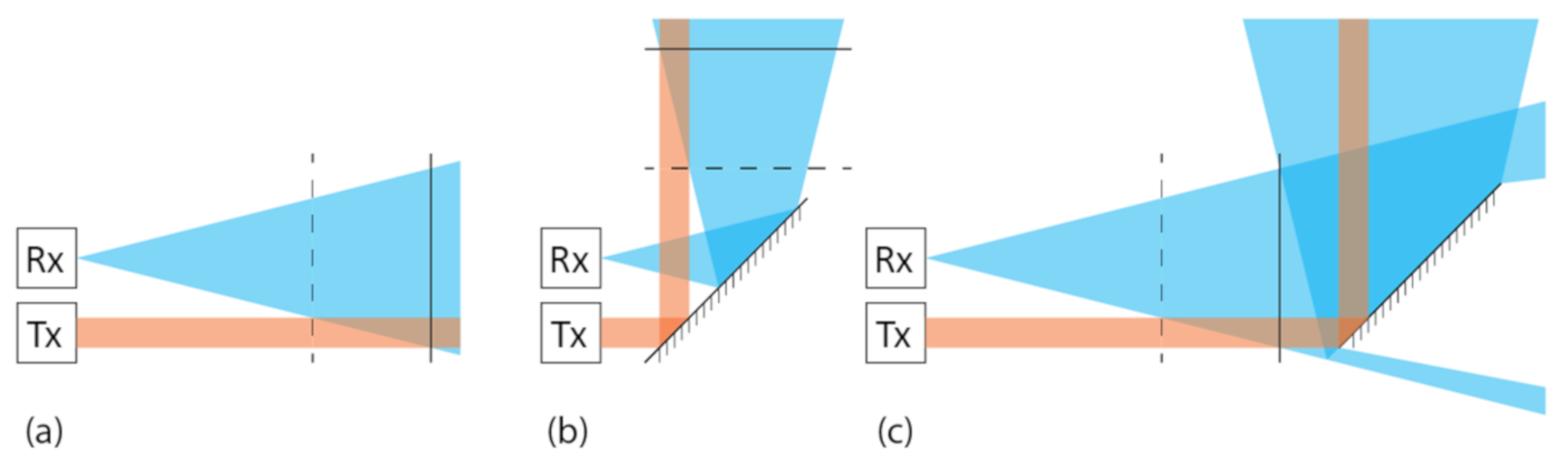
The comparison of how a direct or redirected laser ToF ranging works is depicted in
Figure 1.
Figure 1a shows direct operation,
Figure 1b shows how light FOV can be redirected by using a reflective surface within the devices dead zone, which is commonly used in industrial lidar scanners, and lastly,
Figure 1c shows the operation where the reflecting surface lies beyond the device’s dead zone. Boxes marked Rx and Tx represent light transmitters (lasers) and receivers (photodiodes), respectively. The system’s dead zone ranges from the transmitter/receiver to the dashed line, and partially dead zone extends up to the solid line. While operation between the first two configurations should not be critically different, the third one may pose problems, as any imperfections on the reflecting surface may cause reflections that will interfere with the ranging device’s operation.
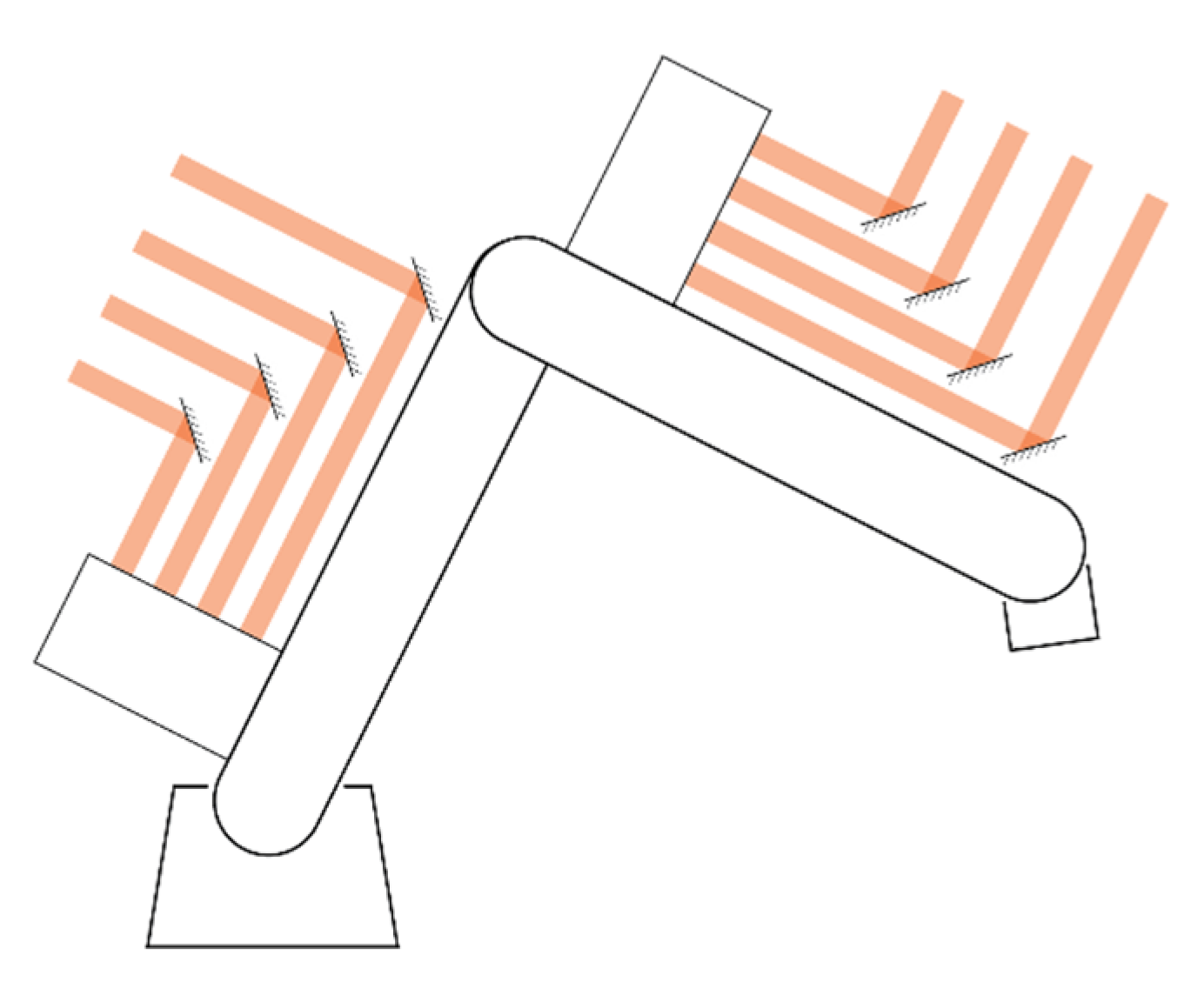
This article addresses a similar approach to redirecting the FOV as described previously, with the major difference that the device used to redirect the FOV is stationary and immovable, with respect to the ranging device. The idea is to transmit a laser beam along the length of the robot’s joint and redirect it perpendicularly outwards when it hits the redirection device. The light, reflected from a target, then travels essentially the same path back to reach the receiver. Multiple optical paths are established along the robot’s segment, leading to a multi-perspective view of the surroundings. A multi-perspective view might provide a significant advantage in monitoring the robot’s surroundings, enabling enhanced safety features. The principle of operation is depicted in
Figure 2, where orange bands represent individual light paths.
2.2. Laser ToF Ranging Device Device
Many commercial ToF-based ranging devices are available on the market as either off the shelf products or as development kits. Those offerings, however, do not offer much insight into what is going on with the measurement. For that reason, we opted to use a custom direct time of flight ranging device, which not only allows us to measure the distance to the target, but also to indirectly observe the amplitude of the return signal. This section discusses the laser ToF ranging device, its construction, and principles of operation.
The laser ToF ranging device that was used has a
laser diode as a light source and an avalanche photodiode (APD) connected to a transimpedance amplifier (TIA), with the gain of
on the receiving end. The receiver APD is also masked with an optical low pass filter to eliminate much of the ambient illumination. The model used is the Optolite IR filter that cuts off light with wavelengths below approximately
. For outdoor use, a band pass filter would be more appropriate but is unnecessary for indoor use, as modern lights produce little to no light in the IR spectrum [
22]. Both the transmitters and the receiver are equipped with focusing optics to achieve a narrow FOV of
. Time of flight measurement is taken care of by a pair of TDC7200 time to digital converters (TDC). This model has a resolution of
(
) and a standard deviation of
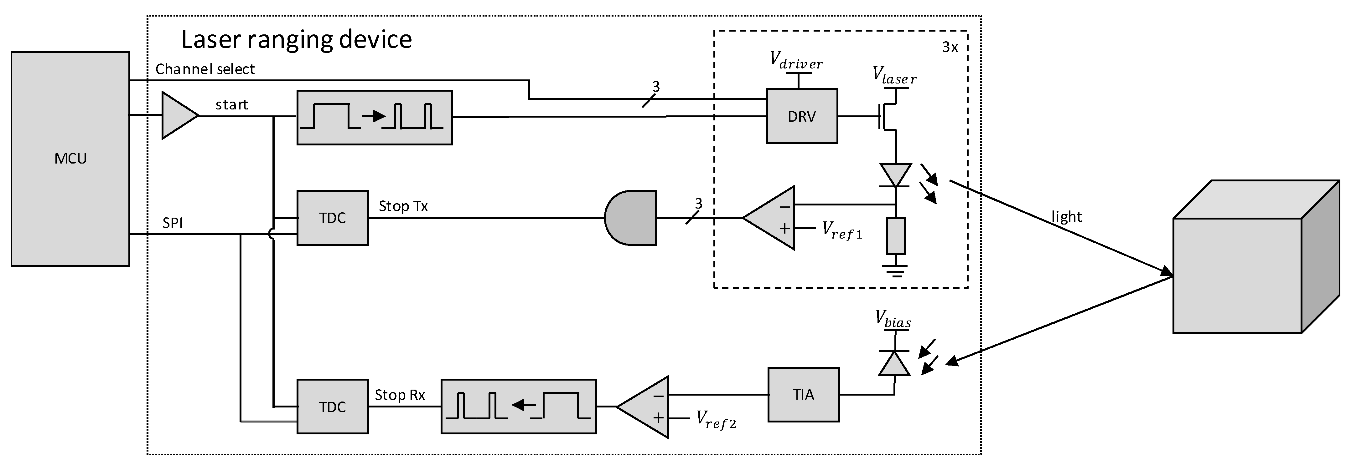
). This is improved by using a running average of eight samples. Both TDCs start the measurement on the positive front of the signal to emit a light pulse but their stop signals are different. One TDC stops the measurement when the current through the laser diode, as measured on a shunt resistor, exceeds the threshold. The other TDC measures both the time of detecting the reflected pulse and its width. This is achieved by passing the signal from the TIA through a comparator with a selected threshold voltage, and then passing the resulting waveform through a pulse generator for both the falling and rising front from the first comparator. The described setup eliminates measurement error that comes from the temperature dependent delay between triggering the transmitted pulse and the laser actually turning on. The system can select between three different illumination channels, all of which trigger the same stop signal for the reference TDC. Ranging is controlled with an external microcontroller. A simplified schematic is shown in
Figure 3. The dashed line encircles components of each of the three equal transmit channels and the dotted line encircles components on the laser ranging device’s printed circuit board (PCB), which comprise the analog front end. Throughout the experiment, only one channel 1, which is located
from the receiver, was used. The remaining two channels will allow the same ranging device to be used in later research.
The microcontroller, which controlled the ranging, was an ATmega328P on an Arduino Nano development board. It was used for generating appropriate transmit pulses and controlling TDCs, which includes initialization, arming, and reading measurement data. The later was sent over to the PC with minimal additional processing carried out on the microcontroller.
2.3. Walk Error
When transmitted light is focused in a parallel beam, the amount of the returned light follows an inverse square law with increasing distance to the target. Total received power for diffuse targets may be estimated using a modified radar Equation (1) [
23], where
is received power,
is receiver gain,
transmitter gain,
power of the transmitted signal,
is the radius of receiving lens (
is its area), and
the distance between measuring device and the target.
in the equation represents the solid angle, at which the light is reflected. In this case it is assumed that the target behaves as a perfect point source that reflects light evenly in the hemisphere towards the light source.
The equation does not take into account the target’s albedo, which provides information on what portion of light is reflected off of the target. This factor could be added to the equation as a multiplicative factor in the fraction’s numerator. The possibility for the target to be non-Lambertian is omitted as well. In such a case, another orientation dependent factor that addresses the material’s physical reflective properties should be added to the equation. Since real materials rarely have a uniform reflection pattern, Equation (1) is only good to obtain a rough estimate for diffuse targets, which remains valid so long as the target’s orientation in regard to the illuminator and the observer is fixed. To summarize the main takeaways, the further the target or lower its albedo, the less signal is captured by the receiving diode. For real signals with finite rise and fall times, the reduction in amplitude effectively shrinks the pulse width after the comparator.
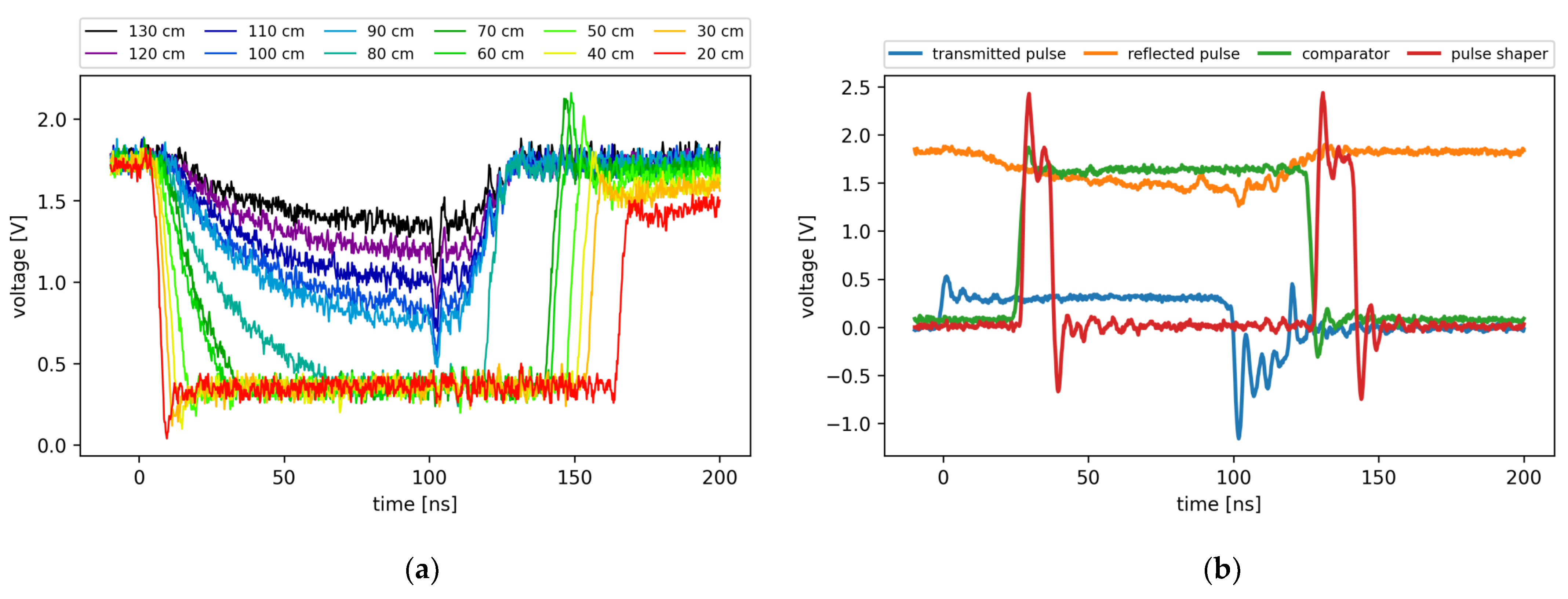
Figure 4a shows the return signal, captured after TIA with the target at different distances. It should be noted that TIA is saturated for signal responses from targets at
or closer. To make the effect more pronounced, a dark target with low albedo was selected when gathering data for
Figure 4a. Traces of different colors represent return signals for measurements with targets at different distances. Which color corresponds to which distance can be read from the legend. For strong return signals, the pulse width can exceed
, which is notably wider than the transmitted pulse, set at
.
The returned signal’s amplitude plays a huge role in when and if the signal will cross the detection threshold, which introduces the walk error. Ideally, neighboring traces in
Figure 4a would cross the threshold, set at
,
apart, the same time it takes the light to traverse the roundabout distance between subsequent measurements. In our case, spread between traces was greater than this and varied by signal strength, as observed in
Figure 4a. Walk error is a systemic error, inherent to ToF based ranging devices [
24]. Some laser ToF ranging devices are constructed so that they do not need additional walk error compensation. More often than not, that is due to having an analog compensation built into the receiver or having a design that is inherently less sensitive to walk error. When that is not the case, walk error compensation has to be implemented to obtain accurate measurements. Common methods for measurement correction for systems with PIN photodiode or APD receivers are based on the signal’s time over threshold (TOT) or rise time. The TOT-based compensation function relies on detected pulse width [
25], and the later one is based on signal’s rise time, measured by the time it takes for the received signal to rise from first threshold to the next [
26]. The ranging device used in this article used TOT-based walk error compensation.
The measured pulse width is a systemic parameter that only depends on the target reflectivity and distance to the target, assuming that the ranging device’s operating parameters, such as supply voltage and temperature, are fixed. TDC7200, the TDC used on the selected ranging device, has the ability to measure time from the start pulse to multiple stop pulses if a sufficient amount of time passes between individual pulses. However, all stop pulses must have the same direction (rising or falling edge). By transmitting a
light pulse and converting the returned signal into two
pulses, one for rising and one for the falling edge of the return signal after passing through a comparator, we ensure that the condition for measuring time to multiple stop pulses is met.
Figure 4b shows the pulse shape of the transmitted pulse, as measured on the shunt resistor (blue), reflected pulse, as measured after TIA (orange), pulse shape after the first comparator (green, and the pulse pair after the pulse shaper (red). The comparator’s and the pulse shaper’s waveforms were attenuated by 50% to make the graph more comprehendible.
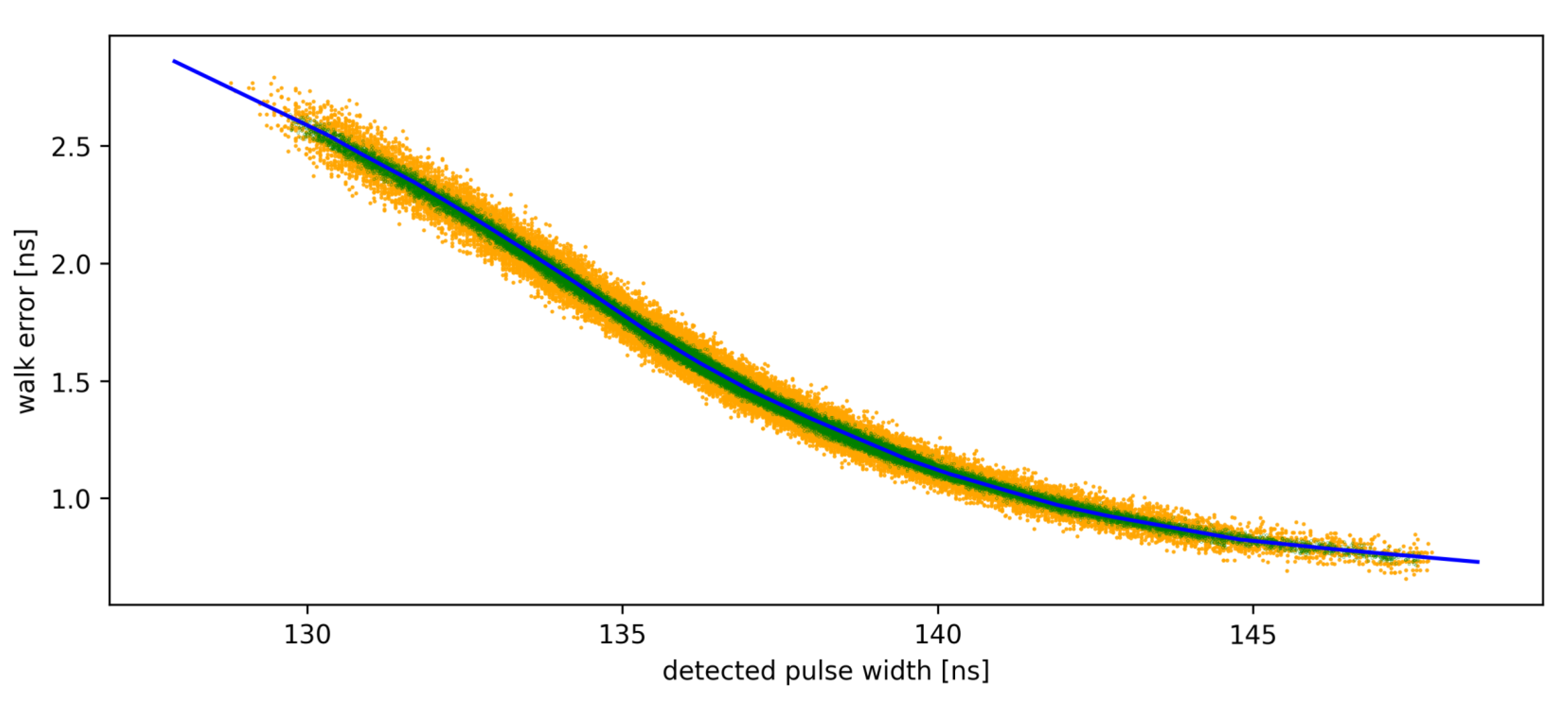
To obtain the compensation function, multiple measurements were taken off of a spinning color wheel with varying albedo, set at multiple different known distances. Both the time to the first stop signal and TOT were recorded for all samples. The difference between measured distance and the expected value (error) versus TOT was plotted, and a piecewise linear (PWL) function was fitted to the resulting data cluster, as shown in
Figure 5. The yellow points correspond to single measurements, the green points are for the data captured with running averages on eight samples, and the solid blue line represents the manual PWL fit. Beyond calibration range, linear continuation with the same coefficient as the last segment within the calibration range is assumed.
After the time from the transmitted to received pulse and the corresponding TOT are measured, walk error compensation is applied. As observed in
Figure 5, a wider pulse means that less time is subtracted from the first stop signal and vice versa. Walk error compensation has to be applied either immediately on the microcontroller or afterwards on the master computer. The later was chosen for our experiments, as we wanted to obtain raw as well as compensated measurements.
2.4. Measurement Setup
This section discusses the tools and procedures used in experiments for this article. It is split into three subsections. In them, measurement hardware, measurement software, and measurement procedure are discussed respectively.
2.4.1. Measurement Hardware
Ranging was carried out using a direct ToF laser ranging device, which was thoroughly discussed in the previous sections. The device was validated in advance to achieve sub centimeter accuracy on the range of zero to eighty centimeters for a range of targets with different albedos. The ToF ranging device was mounted on a stand that allowed for some minor height and angle adjustments.
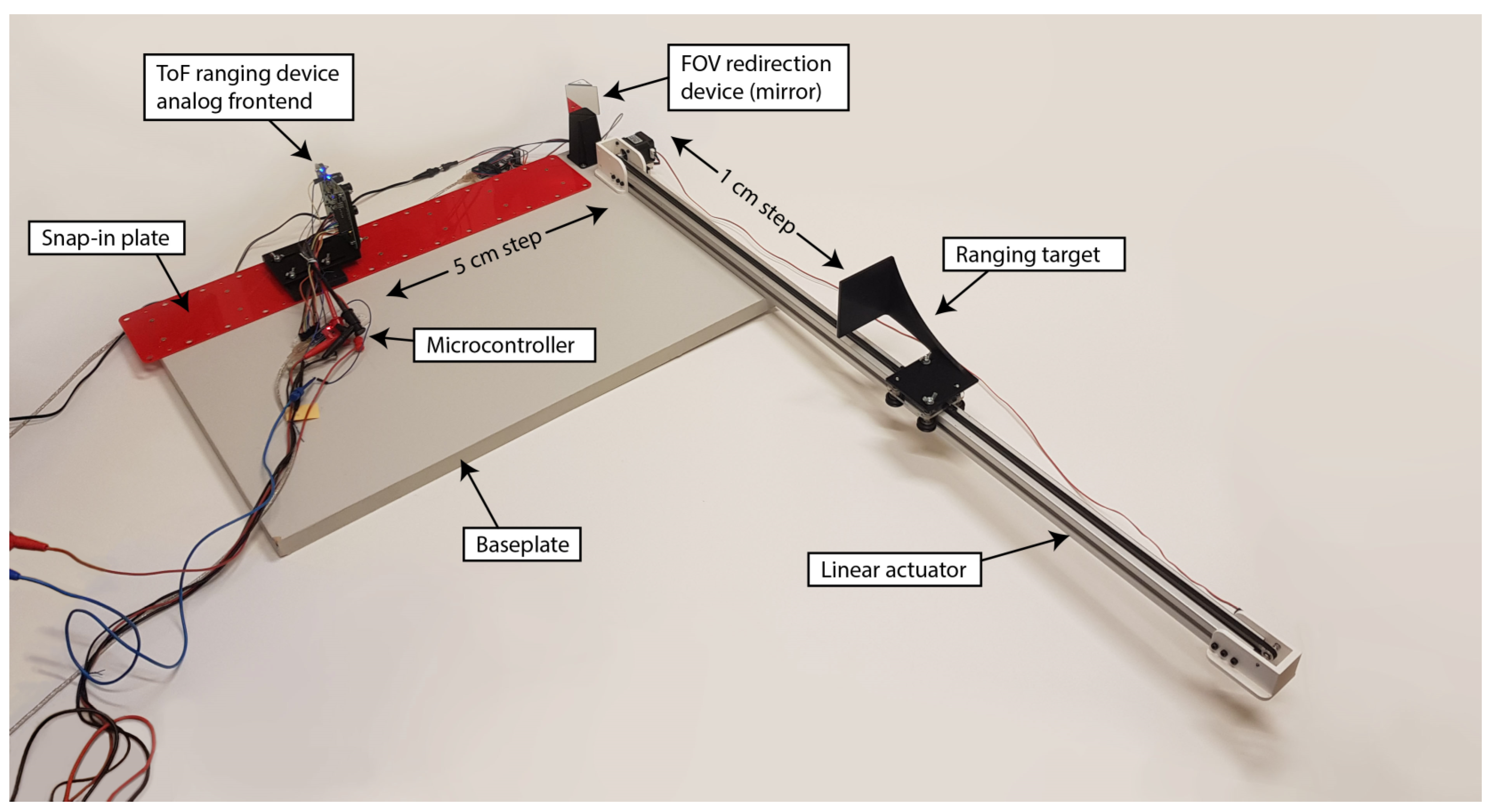
For ranging through an FOV redirection device (mirrors and prisms), a special jig was devised. The jig comprises a linear actuator, and an acrylic snap-in plate, fixedly mounted on a solid particle board baseplate. They were mounted in a way that their axis intersected at a right angle. The FOV redirection device was mounted on a pedestal at the desired height, angle and position. Mirrors were angled at
to both the linear rail and the optical axis of the ranging device. This was the same with the prism, when observing the hypotenuse. Minor adjustments could be made before fixing the stand in place to ensure the desired orientation. That means that experiments were repeatable so long as the redirection device was not changed. The measurement setup is shown in
Figure 6.
Optics for redirecting FOV were Thorlabs’ first surface protected aluminum mirror (ME2S-G01), a generic aluminum back coated mirror from Duratool (S5003), and Knight Optical’s right angle prisms made of N-BK7 glass with AR coated legs (PTK4001). It was known from our previous experiments that using an uncoated prism does not work, as too much light is reflected off of the first surface back into the receiver diode; thus, we did not test that configuration. Mirrors and prism were large enough such that the entire laser beam was safely within the bounds of mirrors or the prism. The target was covered with multiple layers of white office paper. During the aligning process, we made sure that the entire transmitted pulse was hitting the target.
To control for errors rising from variable system parameters, such as temperature and varying voltage levels, all power supplies were left to warm up and then left powered for the entire duration of experiments. The ranging device was left ranging for at least one day before the experimental data were gathered. The walk error compensation curve was recorded on a warmed up system, which was not powered off until all data were collected.
2.4.2. Measurement Software
The ranging device was set in autonomous ranging mode and was continuously sending measurement data to the master PC through a USB serial data link. The microcontroller, connected to the ranging device, was only used to initiate the measurement, gather time of flight data, calculate the running average, and send data over to the master PC with minimal additional processing. Walk error compensation and time to distance conversions were carried out on the PC.
The linear actuator waited for commands to go to the home position, detected by a microswitch, or to move to a desired location. Once the command was executed, the PC was informed that linear actuator is finished with moving.
The master PC was running a python script that took care of setting the linear actuator and saving the ranging data. Data were captured on a span of in increments. For each set distance, 128 raw samples were taken and saved to a file.
2.4.3. Measurement Procedure
For each FOV redirection optic and its configuration, we conducted the same experimental procedure. The ranging device was mounted on the furthermost position () and the target on the linear actuator was set to its furthermost distance as well. Optics, mounted onto a stand, were placed into the ranging device’s FOV such that the laser spot was redirected onto a correct spot on the target. It was ensured that all the transmitted light was hitting either the mirror or the prism, and that all reflected light was hitting the target. Following that, autonomous ranging commenced.
The linear actuator was instructed to move to the home position ( from the optics) and the system started ranging. The target moved one centimeter further away each time, for the total of 80 set distances with 128 raw samples collected at each one.
When data for the entire range were collected, the ToF ranging device was manually moved one position () closer to the redirection optics, and the procedure was repeated for a total capture of eleven datasets per redirection optics configuration.
For the experiments with clean optics, they were thoroughly cleaned using nonwoven cotton wipes (Webril Handi-Pads) damped in isopropanol. When the solvent had evaporated, an optical inspection was conducted. If any streaking or imperfections were observed, the cleaning process was repeated.
2.5. Measurement Data Processing
Data for each optics configuration and each distance between them and the ranging device were saved in individual files. After measurements were completed, data for optics configuration were pooled together and individual datasets were plotted with Python and Matplotlib.
For error plots, all 128 raw samples for each set distance were averaged and the expected measurement was subtracted. Standard deviation was calculated for each distance individually as well. Raw and compensated measurement data were plotted against non-discarded measurement number. Plots for same optics configuration but different distances between them and the optics were overlaid.
4. Discussion
This section discusses the meaning of measured data. Firstly, the direct measurement method is discussed where the importance of walk error compensation is illustrated. Following that, redirecting FOV with mirrors and reasons for the trend of measurement becoming increasingly negative for only some distances between the ranging device and dusted mirror is explained. Our results are also compared to similar data from preexisting studies. Lastly, we take a look at what measurement results for redirecting light with a prism suggest.
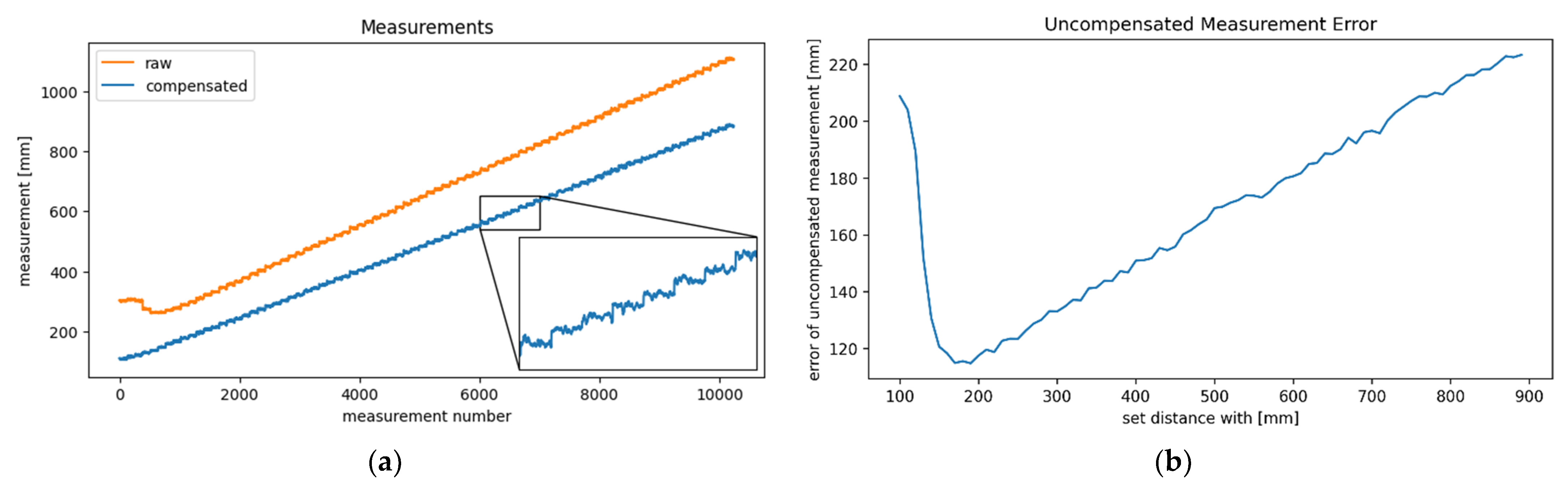
The importance of walk error compensation is observed in
Figure 7a. It shows uncompensated and compensated measurements with orange and blue lines, respectively. It can be observed that the uncompensated measurements show a target at significantly greater distance than expected. Beyond the partially dead zone, the error increases with distance, as best illustrated in
Figure 7b. It shows the uncompensated measurement error versus the set distance.
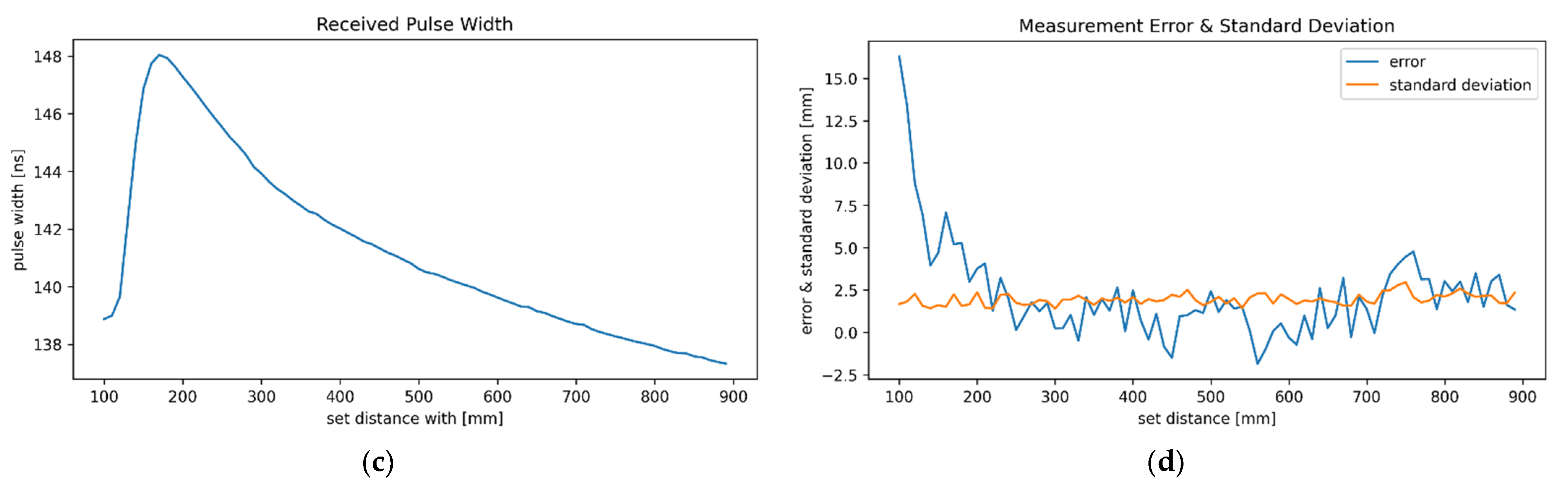
Figure 7c shows the reflected pulse’s width, which decreases with distance beyond the partially dead zone, extending to approximately
beyond the sensor. In this zone, not all transmitted light is in the receiver’s FOV, as illustrated in
Figure 1.
Figure 7d provides a reference for further ranging methods, as it shows the measurement error and the standard deviation of measurements for the direct ranging. A trend observed here and in all remaining measurements is that standard deviation increases slightly with distance but does not vary greatly between different configurations, as it can be observed in
Table 1. It provides an overview of the maximal measurement standard deviations. The values are gathered only from data points where the total distance between the ranging device and target is greater than
, as to eliminate the data points just beyond the ranging device’s dead zone, which shows a large deviation from the expected values even in a direct measurement configuration.
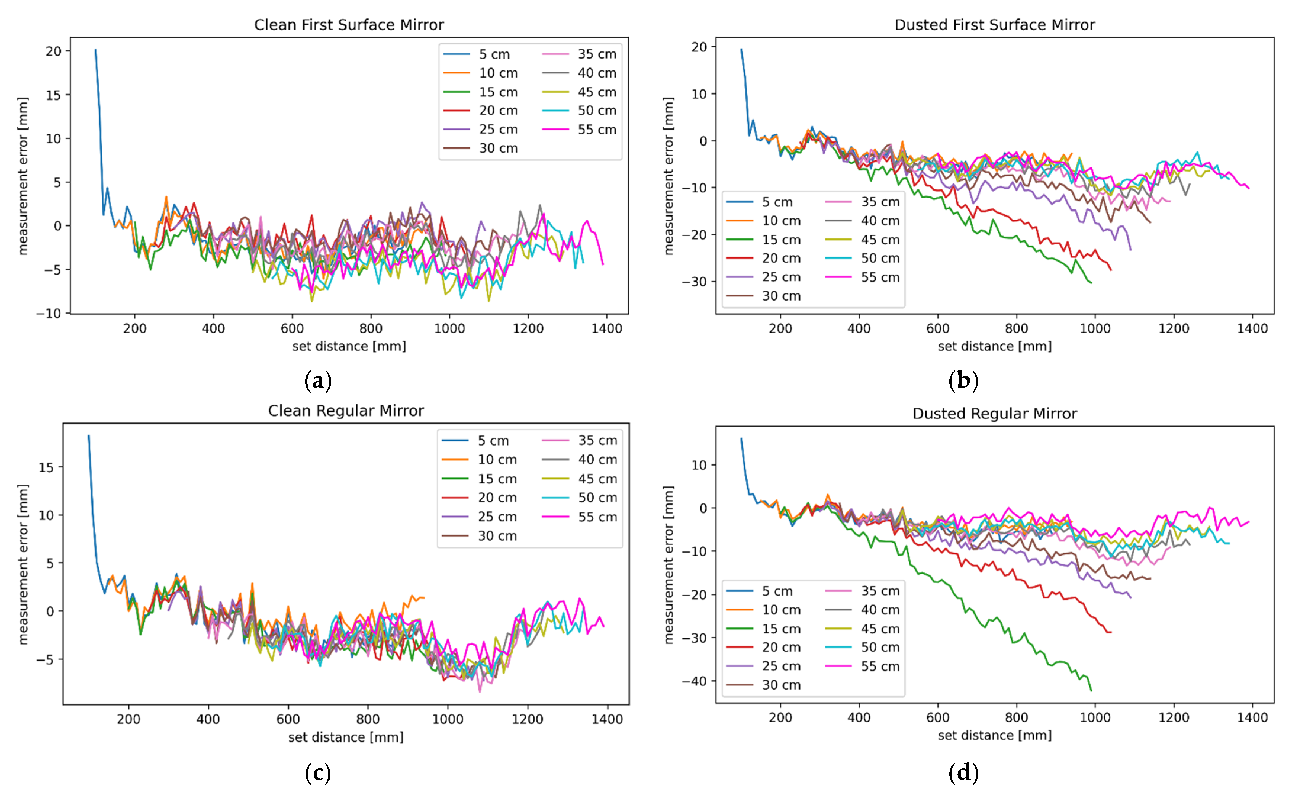
A more or less direct comparison between direct measurements and the ones reflected by a mirror at 5 cm can be made. This is because the minimal distance between the ranging device and target in both cases was
in both cases. By comparing
Figure 8a to
Figure 8c (FOV redirected by a clean first surface and a regular mirror), any differences are within the margin of measurement error and show outstanding similarity in shape. When
Figure 7d (direct measurement) is taken into consideration as well, some minor differences can be observed among the three datasets, but those are once again below the designed accuracy threshold. The rest of the measurements with FOV redirected by a clean mirror were still very similar to the ones obtained directly in the overlapping measurement range.
Worse results were expected for the configurations with dusted mirrors. When comparing measurement results for clean mirrors to their dusted counterparts in
Figure 8b and
Figure 8d for the dusted first surface and regular mirror, respectively, essentially no differences can be observed up to the
mark. From that point on, traces for configurations with the mirror set closer than
from the ranging device continue the same way as in
Figure 8a or
Figure 8b, but the remaining traces trend downwards. The effect diminishes as the distance between the mirror and the ranging device increases. Measurements with the mirror
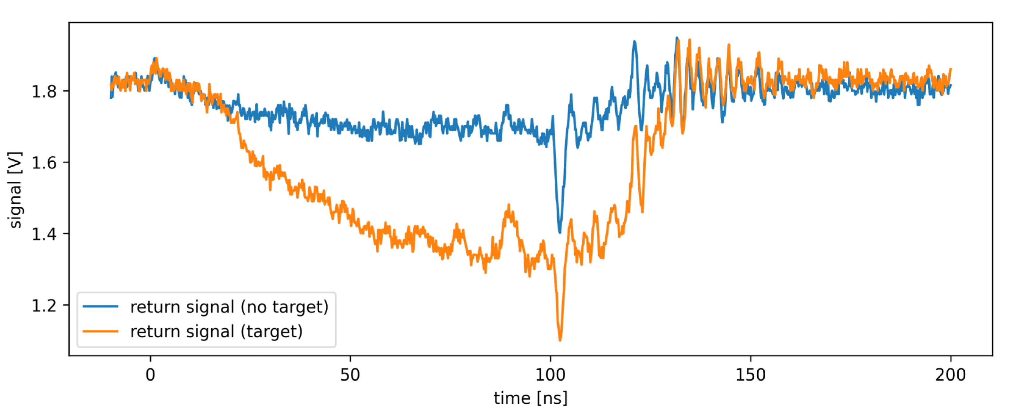
or further from the ranging device seem effectively unaffected by the phenomenon. An explanation for the effect can be found by examining the reflected pulse’s shape, as shown in
Figure 9. When ranging at an infinity, no return signal should be observed, but when ranging at an infinity while redirecting the FOV with a dusted mirror, some weak return signal can be detected (blue trace in
Figure 9). This is a reflection off the dust on the mirror’s surface. It is below the detection threshold on its own, but when ranging on a target is carried out with such a setup, reflections off the target and dust combine into a single pulse (orange trace in
Figure 9), resulting in a measurement error. It comprises two effects, moving the ranging result towards lower measured time, and pulse widening. In a direct time of flight ranging system with TOT-based walk error compensation, those effects work in opposing directions. The first lowers the compensated ranging result, and the other increases it. This study finds that moving the measurement towards lower time has more influence on the ranging, which results in a negative measurement error. As the target moves further away, the desired reflection grows dimmer, but the reflection off the dust remains unchanged. This means that the error will grow in magnitude, which can be observed in error plots in
Figure 8b,d. The effect will be the most pronounced when the mirror is positioned around the end of the partially dead zone, as there the most parasitic reflection will be coupled into the receiver. As observed in
Figure 8b,d, the amount of light from the parasitic reflection is negligible when the mirror is positioned at
from the ranging device or closer. With increasing distance, the parasitic reflection’s intensity decreases alongside its influence on the measurement. Therefore, ranging with a dusted mirror
from the target or further is hardly affected by the parasitic reflection.
The data about the effects of mirrors on ranging characteristics, presented in
Figure 7 and
Figure 8, cannot be directly compared to other researches. In spite of that, some relatable data are found by taking multiple separate researches into account simultaneously. It has been found in [
18] that redirecting Microsoft Kinect 2.0’s FOV with mirrors results in an RMS error ranging between
and
for raw data, which was reduced to roughly
to
after the enhancement algorithm was applied. The data have to be read from the provided graph, as no numerical data were provided. It can be compared to the results of [
27], where a camera’s raw performance was evaluated. The mean measurement error has been found to be within
on the entire advertised measurement range of the Microsoft Kinect 2.0 (
). Even though the data cannot be compared directly because the distance to the object in the first study was not disclosed, it can be observed that the performance of the camera with reflected FOV was close to the study with direct measurements. This confirms our findings that clean mirrors do not have a large influence on the camera’s performance. Another study that can be used for comparison used a movable mirror to redirect a portion of VLP-16’s FOV [
16]. It obtained measurement errors that ranged from comparable to significantly worse than the reference measurements obtained by direct measurements in [
28]. Five of the twelve provided error measurements where FOV was redirected by a mirror that exceeded the advertised measurement tolerance of the lidar, which was in itself twice the expected amount according to [
28]. A large contributor to this discrepancy may have been the tolerances for mirror positioning, as we found measurement results for direct ranging and ranging through a clean mirror to be effectively indistinguishable from one another. The alternative explanation is that the mirror used in [
16] was not clean in at least some parts of the experiments.
In our tests, the use of prisms has proven to be more problematic than mirrors. When a prism is placed within the ranging device’s dead zone, its influence is rather small, although still observable. This can be observed in
Figure 10a, where the blue trace (prism
from the ranging device) trends towards increasingly negative measurement errors as the target moves away. Since the prism’s first leg was in the ranging device’s dead zone, this reflection likely did not contribute much. Therefore, internal reflections are the likely culprit.
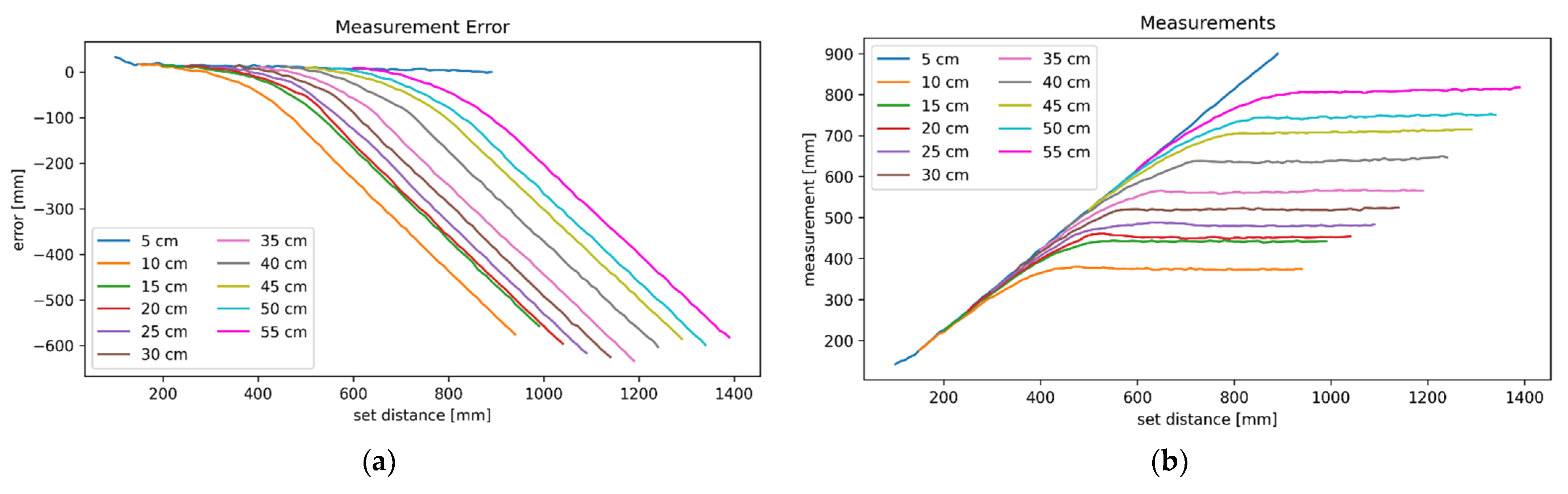
When the prism is positioned
from the ranging device or further in our setup, both of its legs rest within the ranging device’s partially dead zone. This means that reflections off of both surfaces may be coupled straight back into the receiving photodiode. When the target is nearby, the signal’s strength is strong enough to dominate the parasitic reflection; thus, the measurements are accurate. As the target moves further away, its influence slowly diminishes until eventually, the parasitic reflections take over entirely. When this happens, the measurements plateau, which can be clearly observed in
Figure 10b.
The discussed results were obtained with a clean prism with AR coated legs, which is the best-case scenario for redirecting FOV of a light ToF ranging device with a prism. With that in mind, it can be concluded that prisms are inappropriate for redirecting the FOV when the reflecting surfaces are beyond the ranging device’s dead zone.
5. Conclusions
In this article, we explored the influence of first surfaces and regular mirrors, as well as AR-coated prisms, on the performance of a light ToF ranging device with TOT-based walk error compensation. This was carried out for eleven distances to mirrors or prisms, while the target was moved in increments. It has been determined that there is no significant difference between direct measurements and the ones where the FOV was with clean mirrors. Furthermore, there was no significant difference between a first surface or a regular mirror. When the mirror is dusted, the measurements are essentially the same as with direct measurements, so long as the reflecting surface is within the partially dead zone or closer. Beyond that, light reflecting off dust introduces a negative measurement error that is more pronounced when the target is further away. This effect is more noticeable when the mirror is closer to the ranging device. Beyond a certain distance, between the redirection optics and ranging device, dust’s influence on the measurements becomes undetectable. A method for detecting and compensating for the reflection off lint on a mirror might be explored in the future to determine whether redirecting FOVs with mirrors shows potential for use in industrial environments.
This study has also examined the usability of prisms for redirecting FOV of a direct ToF ranging device. As long as the entire prism is well within the ranging device’s partially dead zone or closer, a strong correlation between the set and measured distance can be observed, even though parasitic reflections have some influence on measurements. When the prism is placed further, parasitic reflections quickly exceed and overpower the strength of reflections off the target when the target moves away, at which point the measurements plateau. This was observed in the best-case scenario for the prisms—a clean prism with AR-coated legs. The results of this study show that the prisms in general are not a feasible option for achieving the set goals, unless transmitted and received light paths could be separated entirely.


