Article

Optimal Design of Fluid Flow and Heat Transfer in Pipe Jackets Having Bow Cross-Sections

1
Institute of Mechanical and Electrical Engineering, Beijing University of Chemical Technology, Beijing 100029, China
2
Henan Jinxin Intelligent Technology Co., Ltd., Xinxiang 453011, China
*
Author to whom correspondence should be addressed.
Appl. Sci. 2022, 12(14), 7179; https://doi.org/10.3390/app12147179
Submission received: 23 June 2022 / Revised: 13 July 2022 / Accepted: 13 July 2022 / Published: 16 July 2022

Abstract

:
Pipe jackets are widely used in engineering as a component for heating or cooling reactors or other equipment. In this paper, fluid flow and heat transfer performances in straight or helical pipes having bow cross-sections with the central angle α in the range of 90–180° were numerically simulated using water as the medium under turbulent flow conditions. The results show that, under the same volume flow rate, the bow cross-sectional pipe with α less than 180° can enhance heat transfer and shows better comprehensive heat transfer performance compared with the half-pipe with α being 180°. As a result, less heat exchange surface (or the weight) of the bow cross-sectional pipe is needed for transferring the same amount of heat. Specifically, for the helical pipe having the bow cross-section with α being 90°, the weight of the pipe can be reduced by about 80%. In order to facilitate the engineering design of bow cross-sectional pipe jackets, correlation formulas for Nu and f of the whole straight pipe and the helical pipe were modified to include the influence of the central angle α of the bow cross-sections.

1. Introduction

Pipe jackets are widely used in engineering as a component for heating or cooling reactors or other equipment [1,2]. At present, most pipe jackets are straight or helical pipes with a whole or half circular section. Therefore, the performance of pipe jackets depends on the fluid flow and heat transfer behaviors inside the straight or helical pipes, on which various studies have been conducted. Chu et al. [3] studied the stratified flow of supercritical CO2 in a horizontal pipe under constant heat flow. Xie et al. [4] studied the effect of elliptical dimples on the heat transfer performance of fluids in straight pipes. Dhotre [5] and Jayakumar [6] conducted an experimental study on the heat transfer of the fluid in helical half-coil jackets under laminar and turbulent flow conditions and fitted the heat transfer coefficient correlation. Li et al. [7,8] carried out a numerical study on the fluid flow and heat transfer in the inner and outer half-coil pipe jackets, proposed the correlation formula for heat transfer coefficient and flow resistance, and studied the effect of jacket structure parameters on heat transfer and fluid dynamics. Huang et al. [9] simulated the flow and heat transfer performance of helical pipes with different cross-sections under turbulent conditions, and found that the comprehensive heat transfer performance of the helical pipes with circular cross-sections was the best. Wang et al. [10] studied the laminar flow and heat transfer characteristics of a triangular channel jacket under constant heat flux density and found that the Nusselt number increases with the increase in the Prandtl number and Dean number. Zhang et al. [11] studied the effects of pitch and overlapping form on the heat transfer and resistance characteristics of the fluid in the helical half-coil jackets and pointed out that 1.96 > τ ≥ 1.86 was beneficial to enhance heat transfer. Li et al. [12] studied the effects of dimensionless curvature and Reynolds number on the turbulent flow and heat transfer performance of the fluid in the arch cross-section helical half-pipe jacket in the same heat transfer area. Wang et al. [13] evaluated the flow and heat transfer performance of five arcuate cross-section helical half-pipe jackets, and found that when the Reynolds number and heat transfer area were constant, the Nusselt number of the arcuate cross-section jacket was lower than that of the half-pipe jacket, but the resistance loss was smaller. The comprehensive evaluation factors of pec and JF showed that the performance of the jacket with the arcuate section of 140° was the best under the constant Reynolds number.
As shown in Figure 1, instead of cutting from a whole pipe, a helical half-pipe jacket is manufactured by bending a metal plate into a half-circle transversely while feeding it forward with the roller into a ring in the longitudinal direction [14]. In this regard, the helical pipe does not have to be a half-pipe or even in a circular shape. In fact, a bow cross-sectional pipe jacket is easier to manufacture.
Although investigations of the effects of shapes of cross-sections with some central angles (e.g., 140° [13]) on heat transfer were found in the literature, studies of the engineering application of pipe jackets having different bow cross-sections regarding the optimization in heat transfer and material consumption and correlation formulas of Nu and f needed for process calculations were not addressed. In this paper, numerical simulations were carried out on the fluid flow and heat transfer in both straight pipes and helical pipes having bow cross-sections with different central angles, focusing on the heat transfer enhancement effects and material savings of the bow cross-sectional pipe jackets compared with the half-pipe ones. Correlation formulas for Nu and f of the fluid flow in the bow cross-sectional pipes were proposed to facilitate the engineering design of bow cross-sectional pipe jackets.

2. Numerical Simulation

2.1. Geometrical Model

Without showing the thickness of the pipes, cross-sections with different central angles α (90–180°) are illustrated in Figure 2. Figure 3 shows the helical pipe model where the central angle is 180°.
In this study, three kinds of straight pipes and helical pipes with different pipe diameters were used for numerical simulations. The sizes of the straight pipes were 30, 45 and 60 mm in diameter. The sizes of the helical pipes were 32, 53 and 81 mm (referring to the pipe sizes used in engineering).

2.2. Governing Equations and Boundary Conditions

The continuity, momentum and energy equations are as follows [15]:
ρ u i x i = 0
ρ u i u j x j = x j μ t u i x j + u j x i 2 3 μ t u k x k P x i + ρ g i
ρ u i C p T x i = x i α T μ t T x i + u i x j μ t u i x j + u j x i 2 3 μ t u k x k δ i j
The RNG k-ε two-equation model was adopted for the turbulent region [16]. It can better deal with the flow with a high strain rate and large streamline curvature. The two equations are expressed as follows:
ρ k t + ρ k u i x i = x j α k μ + μ t k x j + G k ρ ε
ρ ε t + ρ ε u i x i = x j α ε μ + μ t ε x j + C 1 ε * k G k C 2 ε * ρ ε 2 k
where the μ t can be expressed as follows:
μ t = ρ c μ k 2 ε
where the C 1 ε * can be expressed as follows:
C 1 ε * = C 1 ε η 1 η / η 0 1 + β η 3
η = 2 E i j E i j 1 / 2 k ε
E i j = 1 2 u i x j + u j x i
with the constants are given as follows:
α ε = α k = 1.39 ,   c μ = 0.0845 ,   C 1 ε * = 1.42 ,   C 2 ε * = 1.68 ,   η 0 = 4.377 ,   β = 0.012
For simulation, the SIMPLEC algorithm was adopted for coupling pressure and velocity. Except for the pressure term, the remaining variables were processed by the second-order upwind style. The velocity inlet and pressure outlet were used. For the boundary conditions, a no-slip constant wall temperature was set for the straight pipe wall. Therefore, the wall boundary condition of the spiral pipe was a no-slip adiabatic on the outer curved wall, and the inner straight wall had a no-slip constant wall temperature [12,13]. The convergence criterion for the energy residual was 10−6, and 10−5 for other parameters.
In this part, the volume flow rate changed with the pipe size to keep the Reynolds number Re in the range of 12,000–24,000, a turbulent flow state. The inlet temperature was set to 20 °C and the temperature of the pipe wall was set to 80 °C for heating the medium inside.
Water at ambient temperature and normal pressure was set as the medium. The specific physical parameters are listed in Table 1 and assumed to be constant in this study, as the temperature was not significantly changed.

2.3. Data Reduction

The Reynolds number (Re), Nusselt number (Nu), friction factor of the straight pipe (fs) and the comprehensive performance evaluation factor (pec) are defined as follows [17].
The Reynolds number is defined as follows:
R e = d e u ρ μ
where u is the fluid flow rate, m/s; ρ is the fluid density, kg·m−3; μ is the dynamic viscosity of fluid, Pa·s; de is the equivalent diameter, m, which is expressed as follows:
d e = 4 A p
where A is cross-sectional area, m2, and p is the wetted perimeter, m.
The Nusselt number can be calculated as:
N u = h d e λ
where h is the heat transfer coefficient, W·m−2·K−1; λ is the fluid thermal conductivity, W·(m·K)−1.
The friction resistance coefficient of the straight pipe is calculated by the Darcy friction coefficient formula as follows:
f s = 2 Δ P d e ρ L u 2
where ∆P is the pressure drop between the inlet and outlet of the pipe, MPa; L is the pipe length, m.
The friction resistance coefficient of the helical pipe is calculated by the Fanning friction coefficient formula as follows [12]:
f h = Δ P d e 2 ρ L u 2
Nusselt number and frictional resistance coefficient of the fluid are two important properties for a pipe jacket as a component performing heating or cooling functions for reactors or other components in engineering. Enhancing heat transfer is always at the cost of increasing flow resistance or pressure drop. Therefore, in engineering, the comprehensive performance evaluation factor pec is sometimes used to evaluate the comprehensive performance of helical pipe jackets, and is defined as follows:
p e c = N u / N u 0 f / f 0 1 / 3
where Nu and f are the average Nusselt number and friction resistance coefficient of the fluid in the pipe; Nu0 and f0 are the average Nusselt number and frictional resistance coefficient of the fluid in the pipe with α being 180°.

2.4. Mesh and Simulation Verification

As shown in Figure 4, tetrahedral elements were used to mesh the medium domain inside the straight pipes. Mesh-independence tests were performed for Nu and f, and the results are listed in Table 2. Clearly, the element number of 1,920,556 is suitable considering the calculation cost and the resulting error comprehensively.
The helical pipe was meshed with Poly-Hexcore elements, which can effectively reduce the number of elements and improve the solution speed. The mesh model is shown in Figure 5. Similarly, a mesh-independence test was conducted, and the results are listed in Table 3. As a result, the mesh model with 2,326,812 elements was selected in this study.
The Dittus–Boelter formula [18] and Blasius formula [19] for straight pipes and correlations given by the literature [20,21] for helical pipes were applied to verify the accuracy of the numerical simulations using the above models, in terms of the average Nusselt number Nu and frictional resistance coefficient f. The formulas are as follows:
N u = 0.023 R e 0.8 P r 0.4
f = 0.316 / R e 0.25
N u = 0.023 R e 0.85 P r 0.4 δ 0.1
f = 0.076 R e 0.25 + 0.00725 ( D c / d ) 0.5
where Pr is the Prandtl number; δ is the curvature ratio, δ = d/Dc; d is the pipe inner diameter, mm; Dc is the curvature diameter, mm, Dc = 2Rc.
The results are shown in Figure 6 and Figure 7, respectively, where the medium is water and the straight pipe is 30 mm in diameter and 1000 mm in length, and the helical pipe is 32 mm in pipe diameter, 100 mm in pitch and 500 mm in helical diameter. It is seen that the numerical simulations are in good agreement with the correlation calculated results. The absolute values of the relative errors of Nu and f for the straight pipe are 0.53–7.55% and 3.67–6.74%, respectively, and the absolute values of the relative errors of Nu and f for the helical pipe are 2.53–6.73% and 1.82–6.33%, respectively, indicating that the simulation method in this paper is reliable.

3. Results and Discussion

3.1. Optimal Design of Pipe Cross-Sections

For developing high-efficiency heat exchange structures, researchers usually compare heat transfer results for a given Re number [22,23,24]. However, in this study, as the pipe jackets are designed to achieve a specific amount of heat with a needed volume flow rate of cooling or heating water in the pipes, keeping the volume flow rate constant for a given pipe having a bow cross-section with different central angles and comparing heat transfer efficiency would be more meaningful in engineering. In addition, in engineering practice, the volume flow rate should be changed with the variation in medium temperatures inside, for example, reactors while keeping the flow in a turbulent flow state.
Under the condition of the same volume flow rate for the same pipe size, the variations in Re, Nu and f with α are shown in Figure 8, Figure 9, Figure 10, Figure 11, Figure 12 and Figure 13 in relative values compared with the corresponding items in half-pipes with α equal to 180° for different pipe sizes represented by ∅ for the inner diameter. It is seen from Figure 8, Figure 9, Figure 10 and Figure 11 that both Re/Re0 and Nu/Nu0 for the straight pipe and the helical pipe decrease monotonically with increasing α, which is understandable because a small α gives a small bow cross-section and, thus, a large flow velocity. It was also found that the variation in Re/Re0 and Nu/Nu0 with α for both straight and helical pipes is the same and has nothing to do with the pipe size; the reason for this result is that, by using relative quantities, the effect of the volume flow rate is eliminated.
Figure 12 and Figure 13 show the relative frictional resistance coefficient f/f0 changing with α for different pipe sizes. f/f0 decreases with decreasing α, meaning that the pressure drop increases when α decreases, which is expected since a small α gives a small cross-section and, thus, a large flow velocity.
Figure 14 and Figure 15 show the comprehensive performance evaluation factor pec of the straight pipes and the helical pipes changing with the central angle α. It is seen that the pec of the straight pipes and the helical pipes for α less than 180° is greater than 1 for α equal to 180°, which means that the comprehensive heat transfer performance of the pipe with α less than 180° is better than that of α equal to 180°. With increasing α, pec decreases, indicating that the smaller the α is, the better the comprehensive performance of the pipe will be. In the range of 90°–180°, the comprehensive heat transfer effect is the best when α is 90°. Again, for all pipe sizes, the variation in pec with α is the same.
Cost should always be considered for the design of pipe jackets, which is directly related to the weight of the pipes. For a given pipe size, the thickness is the same although the central angle α could be different, so the weight of a pipe can be affected by the wetted surface, which is the product of the pipe length and the wetted perimeter. Figure 16 and Figure 17 show the relative consumed weight W/W0 changing with the central angle α for straight pipes and helical pipes when α changes from 90° to 180° while keeping the volume flow rate and the transferred heat for each pipe size the same. Obviously, the smaller the central angle α of the bow cross-section of the pipes, the smaller the weight of the pipe. Specifically, for straight pipes of ∅30, ∅45 and ∅60, when α is 90°, the pipe weight can be reduced by 80.15%, 79.62% and 79.47%, respectively, compared with that of half-pipes at α equal to 180°. For helical pipes of ∅32, ∅53 and ∅81, the wetted surface or the weight of the pipe with α being 90° can be reduced by 82.53%, 83.66% and 83.48%, respectively.
In general, the results obtained in this section indicate that for the same volume flow rate, compared with the half-pipe with α equal to 180°, the bow cross-sectional pipe with α less than 180° presents higher heat transfer efficiency and, thus, needs less heat exchanging surface for transferring the same quantity of heat.

3.2. Modification of Nu and f Correlation Formulas for Bow Cross-Section Pipes

It was found that when the pipe cross-section is not a full circle, or, in other words, when the central angle α of the cross-section is not 360°, errors of the Nusselt number Nu and frictional resistance coefficient f calculated by the existing correlation Formulas (16)–(19) are relatively large. In this study, in order to more accurately evaluate Nu and f for bow cross-section pipes, the correlation Formulas (16)–(19) were modified by taking into account the influence of α based on a large number of numerical calculations. The corrected correlations for calculating Nu and f of straight pipes are Formulas (20) and (21) with the scope of application: 12,000 ≤ Re ≤ 24,000, 90° ≤ α ≤ 180°, 30 mm ≤ d ≤ 60 mm. The modified formulas were verified numerically and the results are listed in Table 4. It is seen that, within the scope of application, the modified correlations are in good agreement with the simulated results and the relative errors are within 10%, which can be better used to calculate the Nusselt number and frictional resistance coefficient of straight pipes with a bow cross-section.
N u = 0.026 R e 0.8 P r 0.4 α 360 0.155
f = 0.327 R e 0.25 α 360 0.165
Similarly, for the helical bow pipe, the correlation Formulas (18) and (19) were also modified into Formulas (22) and (23), respectively, where the applicable range is: 12,000 ≤ Re ≤ 24,000, 90° ≤ α ≤ 180°, 32 mm ≤ d ≤ 81 mm, 450 mm ≤ Dc ≤ 1000 mm. Numerical verifications are listed in Table 5. It is seen that, within the applicable range, errors between the modified correlations and the simulations are within 10%, which can be better used to calculate the Nusselt number and frictional resistance coefficient of helical pipes with a bow cross-section.
N u = 0.0185 R e 0.85 P r 0.4 d D c 0.1 α 360 0.075
f = 0.059 R e 0.25 + 0.017 D c d 0.5 α 360 1.399

4. Conclusions

In this paper, the numerical simulations were carried out on the fluid flow and heat transfer in straight pipes and helical pipes having bow cross-sections with different central angles. Conclusions are drawn as follows:
(1)
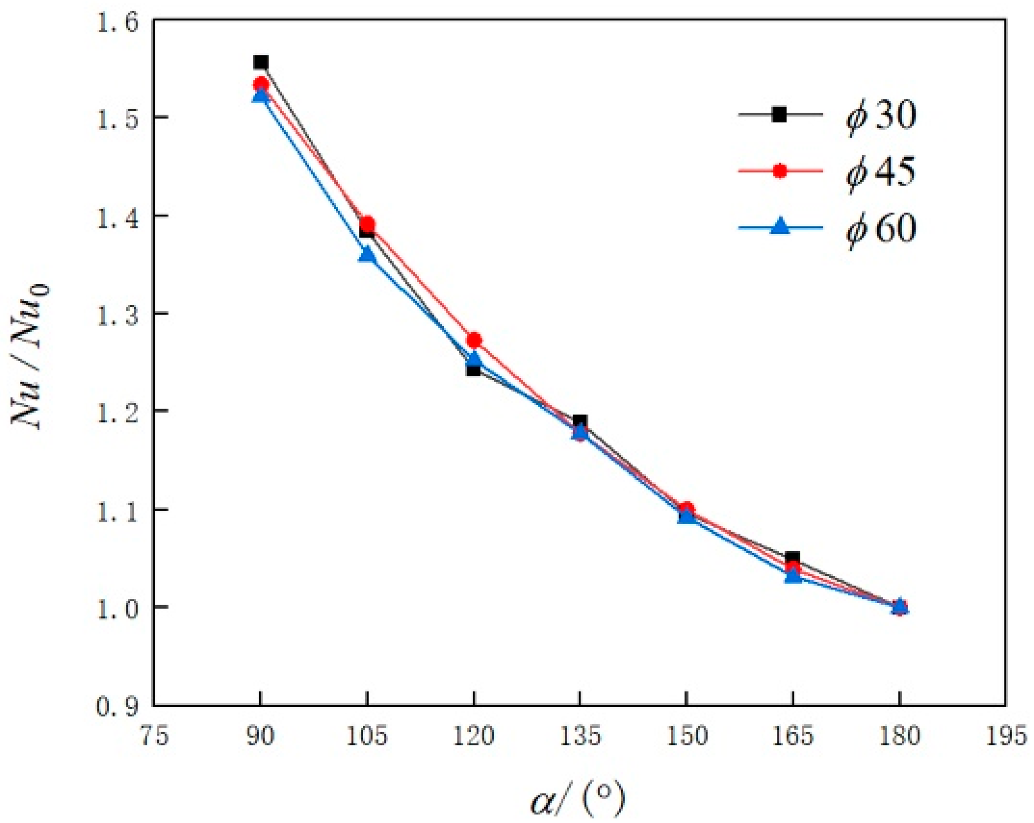
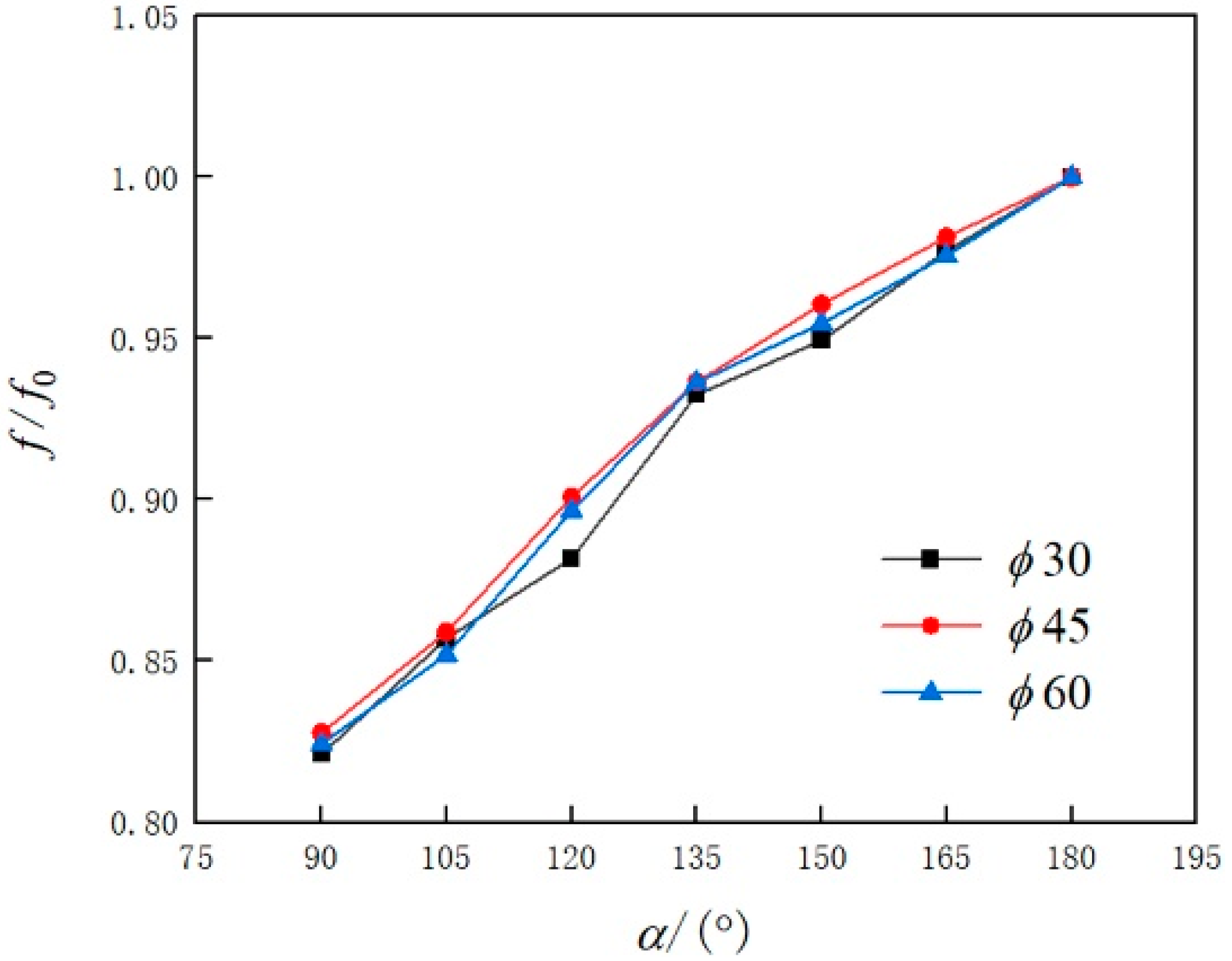
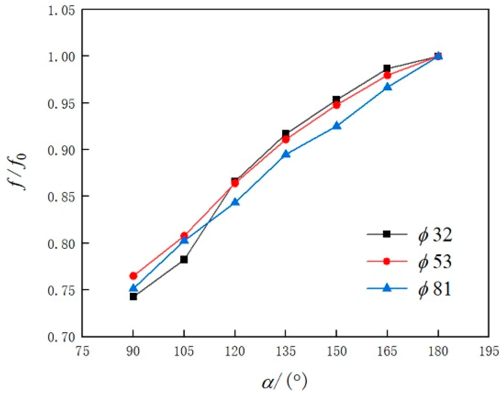
For a given volume flow rate, by decreasing the central angle α of the bow cross-sections in the range of 90–180°, Re and Nu for both straight pipes and helical pipes increase, meaning that the bow cross-sections can enhance heat transfer in the pipes. However, at the same time, the flow resistance will also increase.
(2)
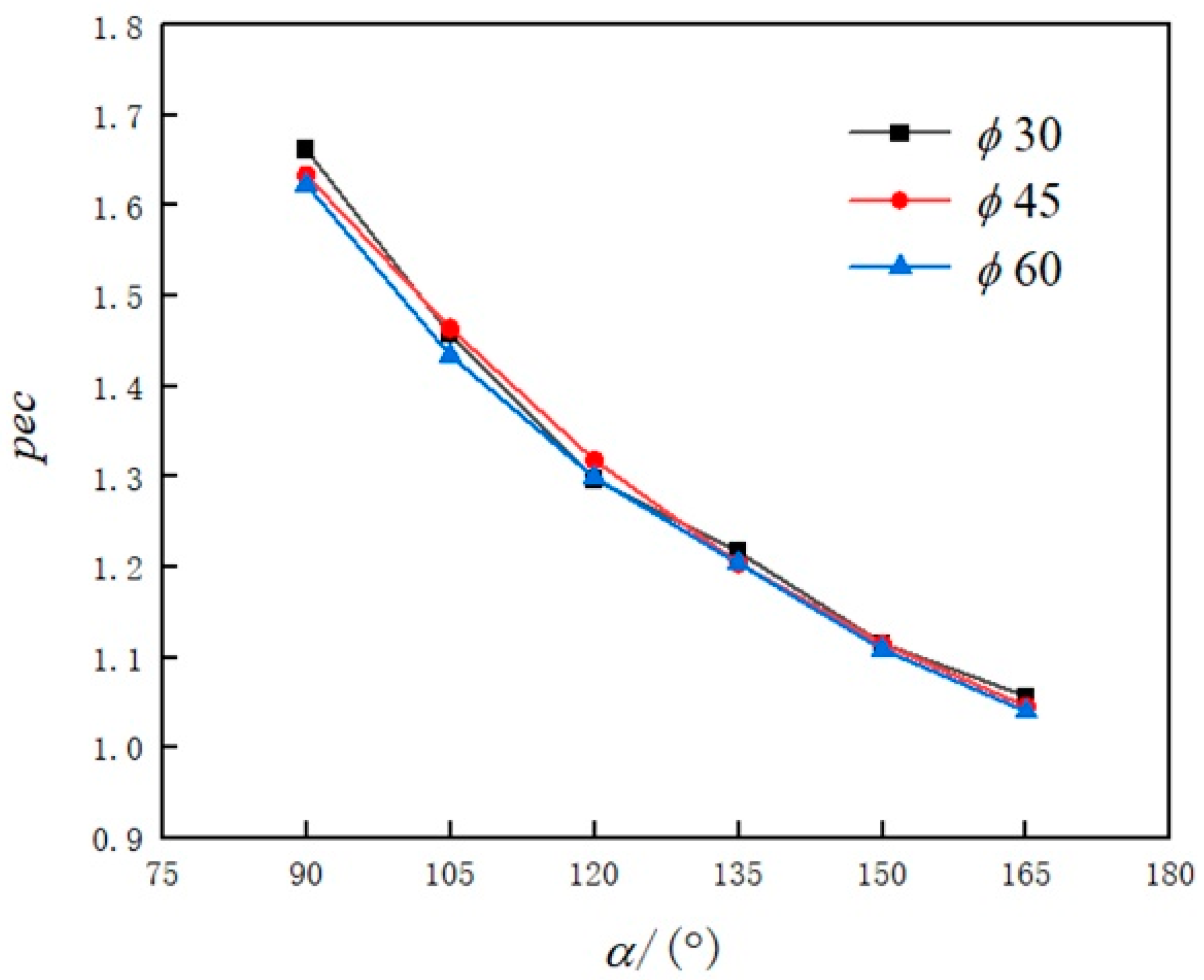
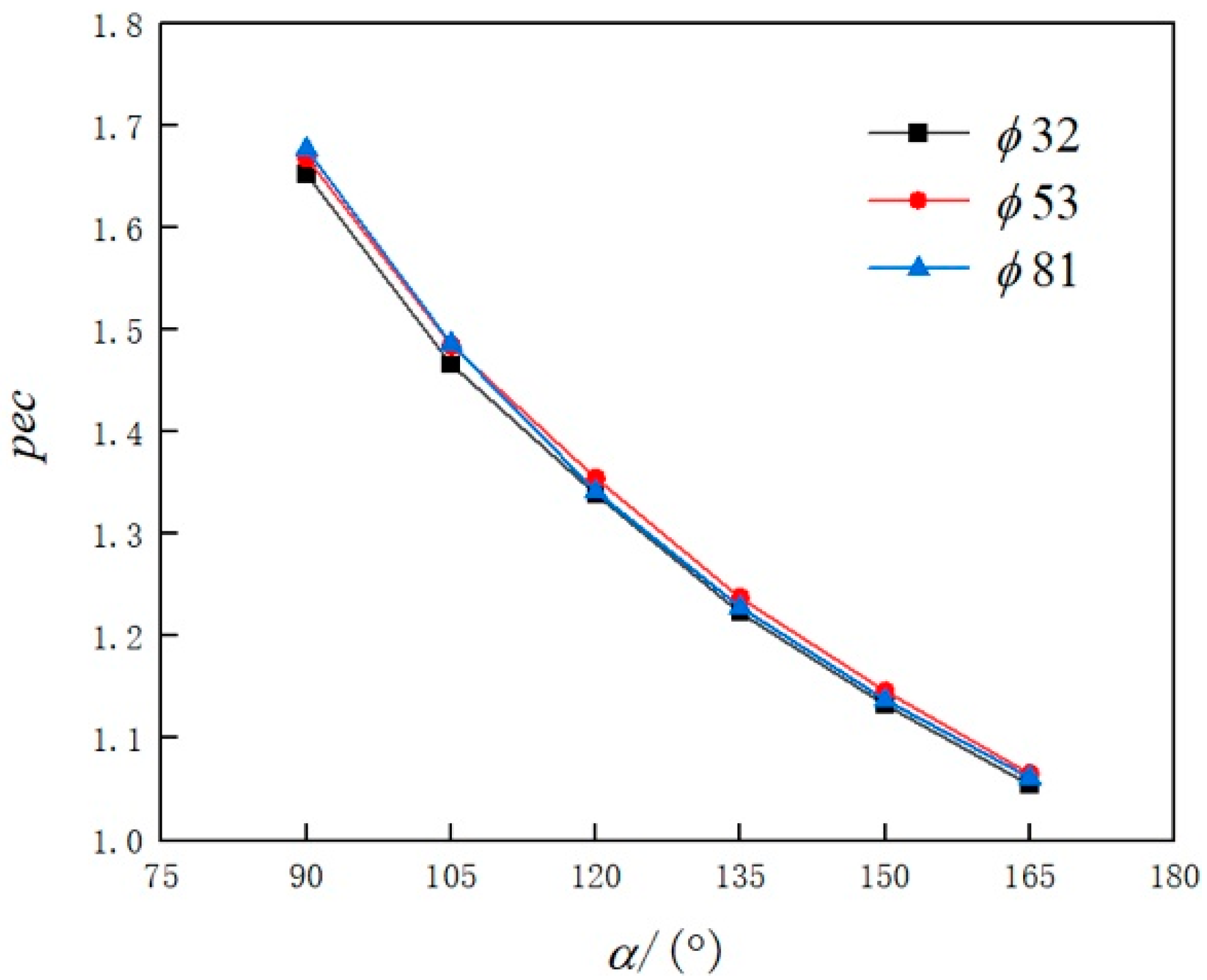
Compared with half-pipes with the central angle α being 180°, the comprehensive performance evaluation factor pec for both straight pipes and helical pipes having bow cross-sections is greater than 1, meaning that bow cross-sectional pipes have better comprehensive heat transfer performance. Specifically, for the helical pipes, when α is 90°, the pec can reach 1.68 times that with α being 180°.
(3)
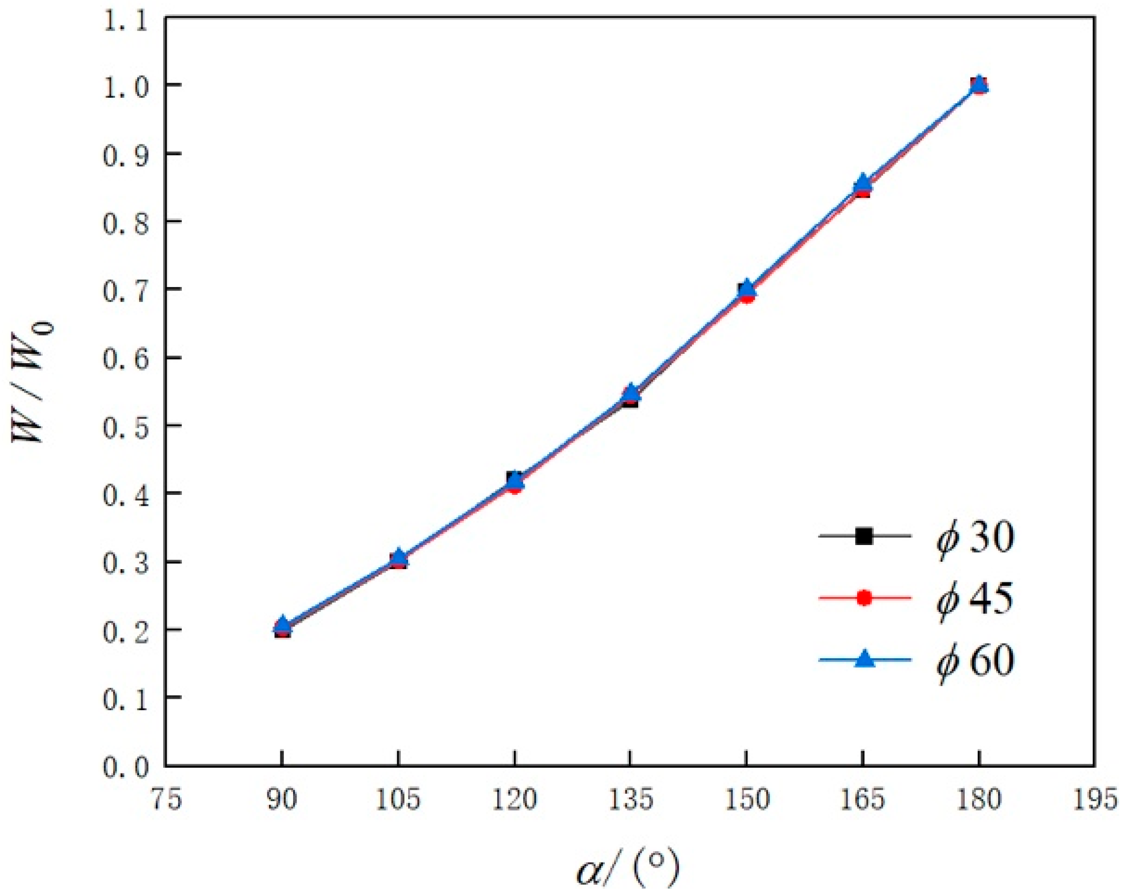
Compared with the half-pipe with α equal to 180°, less weight of the bow cross-sectional pipe is needed for transferring the same amount of heat. For the helical pipe having a bow cross-section with α being 90°, the weight of the pipe can be reduced by about 80%, a significant saving of the material or the manufacturing cost;
(4)
Correlation formulas for Nu and f of the whole straight pipe and the helical pipe were modified to include the influence of the central angle α of the bow cross-sections. With relative errors of less than 10%, the modified formulas can be applied in engineering to construct jackets with bow cross-sectional pipes.
As mentioned in the Introduction and shown in Figure 1, pipe jackets are manufactured by bending and feeding metal plates into rings rather than cutting from whole pipes. Obviously, a pipe jacket with a bow cross-section with a central angle of less than 180° is easier to manufacture than a half-pipe jacket. Therefore, together with the higher heat transfer ability and fewer consumed materials found in this study, using bow cross-sectional pipes to construct jackets is more economic compared with half-pipes and should be adopted preferentially in engineering, with the design based on the correlation formulas for Nu and f proposed in this paper.

Author Contributions

Conceptualization, X.Y. and C.Q.; methodology, C.Q.; software, W.L.; validation, Z.W.; formal analysis, W.L. and Z.W.; investigation, X.Y. and C.Q.; resources H.L.; data curation, W.L. and Z.W.; writing—original draft preparation, W.L.; writing—review and editing, X.Y. and C.Q.; visualization, Z.W.; supervision, H.L.; project administration, H.L.; funding acquisition, H.L. All authors have read and agreed to the published version of the manuscript.

Funding

This research received no external funding.

Institutional Review Board Statement

Not applicable.

Informed Consent Statement

Not applicable.

Data Availability Statement

Data available on request.

Conflicts of Interest

The authors declare no conflict of interest.

References

  1. Gai, C.; Zheng, X.; Wang, C.; Zhou, N.; Xiao, J. Finite element stress analysis of vessel with half-pipe jacket. J. Wuhan Inst. Technol. 2011, 33, 77–80. [Google Scholar]
  2. Deng, X. The Development and Application of the Spiral Semicircle Double-Layered Reactor. Press. Vessel. Technol. 2001, 18, 45–47. [Google Scholar]
  3. Chu, X.; Laurien, E. Flow stratification of supercritical CO2 in a heated horizontal pipe. J. Supercrit. Fluids 2016, 116, 172–189. [Google Scholar] [CrossRef]
  4. Xie, S.; Liang, Z.; Zhang, L.; Wang, Y. A numerical study on heat transfer enhancement and flow structure in enhanced pipe with cross ellipsoidal dimples. Int. J. Heat Mass Transf. 2018, 125, 434–444. [Google Scholar] [CrossRef]
  5. Dhotre, M.T.; Murthy, Z.V.P.; Jayakumar, N.S. Modeling & dynamic studies of heat transfer cooling of liquid in half-coil jackets. Chem. Eng. J. 2006, 118, 183–188. [Google Scholar] [CrossRef]
  6. Subramanian, J.N.; Mjalli, F.S. The dynamics of liquid cooling in half-coil jackets. Chem. Prod. Process Model. 2008, 3, 1264. [Google Scholar] [CrossRef]
  7. Li, Y.; Wu, J.; Zhan, H.; Wang, C. Fluid flow and heat transfer characteristic of outer and inner half coil jackets. Chin. J. Chem. Eng. 2011, 19, 253–261. [Google Scholar] [CrossRef]
  8. Li, Y.; Wu, J.; Zhang, L.; Kou, L. Comparison of fluid flow and heat transfer behavior in outer and inner half coil jackets and field synergy analysis. Appl. Therm. Eng. 2011, 31, 3078–3083. [Google Scholar] [CrossRef]
  9. Huang, Y.; Huang, Y.; Wang, W. Numerical research on flow and heat transfer in helically coiled pipes with different cross-sections. Comput. Appl. Chem. 2016, 33, 1261–1266. [Google Scholar] [CrossRef]
  10. Wang, C.; Liu, S.; Wu, J.; Li, Y. Laminar flow and heat transfer characteristics in jackets of triangular flow channels. Chin. J. Chem. Eng. 2013, 21, 1224–1231. [Google Scholar] [CrossRef]
  11. Zhang, J.; Zhang, Y.; Wu, J. Effect of Varying Pitch and Overlap Scale on Enhanced Heat Transfer of Half-coil Jackets. The Chin. J. Process Eng. 2017, 17, 697–703. [Google Scholar] [CrossRef]
  12. Li, Y.; Lan, L.; Wu, J. Fluid Flow and Heat Transfer Characteristic in the Half-Pipe Coiled Jacket with Arch Cross Section. Contemp. Chem. Ind. 2012, 41, 1291–1294. [Google Scholar] [CrossRef]
  13. Wang, L.; Liao, X.; Li, H. Evaluation of flow and heat transfer performance of spiral coil jacket with different cross sections. J. Phys. Conf. Ser. 2022, 2235, 012036. [Google Scholar] [CrossRef]
  14. Wei, L.; Xiao, X.; Hao, W. The Design and Manufacture of Half Pipe Jacket. China Chem. Ind. Equip. 2017, 19, 45–48. [Google Scholar]
  15. Xu, X.; Wu, Y.; Liu, C.; Wang, K.; Ye, J. Numerical study of cooling heat transfer of supercritical carbon dioxide in a horizontal helically coiled pipe. Acta Phys. Sin. 2015, 64, 258–264. [Google Scholar] [CrossRef]
  16. Yang, M.; Li, G.; Liao, F.; Li, J.; Zhou, X. Numerical study of characteristic influence on heat transfer of supercritical CO2 in helically coiled pipe with non-circular cross section. Int. J. Heat Mass Transf. 2021, 176, 121511. [Google Scholar] [CrossRef]
  17. Zhang, C.; Wang, D.; Xiang, S.; Han, Y.; Peng, X. Numerical investigation of heat transfer and pressure drop in helically coiled pipe with spherical corrugation. Int. J. Heat Mass Transf. 2017, 113, 332–341. [Google Scholar] [CrossRef]
  18. Yao, Y.Y.; Huang, F.L.; Chen, C.G.; Chai, C.J. Principles of Chemical Engineering; Tianjin University Press: Tianjin, China, 1999; pp. 336–342. [Google Scholar]
  19. Itō, H. Friction Factors for Turbulent Flow in Curved Pipes. J. Basic Eng. 1959, 81, 123–132. [Google Scholar] [CrossRef]
  20. Lin, C.X.; Ebadian, M.A. Developing turbulent convective heat transfer in helical pipes. Int. J. Heat Mass Transf. 1997, 40, 3861–3873. [Google Scholar] [CrossRef]
  21. Cioncolini, A.; Santini, L. An experimental investigation regarding the laminar to turbulent flow transition in helically coiled pipes. Exp. Therm. Fluid Sci. 2006, 30, 367–380. [Google Scholar] [CrossRef]
  22. Błasiak, P.; Pietrowicz, S. An experimental study on the heat transfer performance in a batch scraped surface heat exchanger under a turbulent flow regime. Int. J. Heat Mass Transf. 2017, 107, 379–390. [Google Scholar] [CrossRef]
  23. Błasiak, P.; Pietrowicz, S. Towards a better understanding of 2D thermal-flow processes in a scraped surface heat exchanger. Int. J. Heat Mass Transf. 2016, 98, 240–256. [Google Scholar] [CrossRef]
  24. Błasiak, P.; Pietrowicz, S. A numerical study on heat transfer enhancement via mechanical aids. Int. J. Heat Mass Transf. 2019, 140, 203–215. [Google Scholar] [CrossRef]
Figure 1. Manufacture of helical half-pipe jackets.
Applsci 12 07179 g001
Figure 2. Illustration of the pipes having bow cross-sections with different central angles.
Applsci 12 07179 g002
Figure 3. Illustration of a helical pipe jacket model.
Applsci 12 07179 g003
Figure 4. Mesh model for straight pipes.
Applsci 12 07179 g004
Figure 5. Mesh model of helical pipe.
Applsci 12 07179 g005
Figure 6. Verification of the numerical simulations in the straight pipe.
Applsci 12 07179 g006
Figure 7. Verification of the numerical simulations in the helical pipe.
Applsci 12 07179 g007
Figure 8. Relative Reynolds number Re/Re0 changing with the central angle α for straight pipes.
Applsci 12 07179 g008
Figure 9. Relative Reynolds number Re/Re0 changing with the central angle α for helical pipes.
Applsci 12 07179 g009
Figure 10. Relative Nusselt number Nu/Nu0 changing with the central angle α for straight pipes.
Applsci 12 07179 g010
Figure 11. Relative Nusselt number Nu/Nu0 changing with the central angle α for helical pipes.
Applsci 12 07179 g011
Figure 12. Relative frictional resistance coefficient f/f0 changing with the central angle α for straight pipes.
Applsci 12 07179 g012
Figure 13. Relative frictional resistance coefficient f/f0 changing with the central angle α for helical pipes.
Applsci 12 07179 g013
Figure 14. Comprehensive performance evaluation factor pec changing with the central angle α for straight pipes.
Applsci 12 07179 g014
Figure 15. Comprehensive performance evaluation factor pec changing with the central angle α for helical pipes.
Applsci 12 07179 g015
Figure 16. Relative consumed weight W/W0 changing with the central angle α for straight pipes.
Applsci 12 07179 g016
Figure 17. Relative consumed weight W/W0 changing with the central angle α for helical pipes.
Applsci 12 07179 g017
Table 1. Physical parameters of water.
ParameterValue
Cp4182 J·(kg·K)−1
μ0.001003 Pa·s
ρ998.2 kg·m−3
λ0.6 W (m·K)−1
Table 2. Mesh-independence test for straight pipes.
Mesh NumberNuError (%)fError (%)
929,583168.520.380.0237−1.66
1,920,556168.360.290.0239−0.83
3,945,627167.8800.02410
Table 3. Mesh-independence test for helical pipes.
Mesh NumberNuError (%)fError (%)
1,164,67284.502−0.750.00720−2.04
2,326,81284.846−0.340.00726−1.22
4,628,35585.13800.007350
Table 4. Verification of the modified formula for straight pipes.
α (°)Red
(mm)
Nu
(Simulation)
Nu
with Equation (11)
Relative Error
(%)
f
(Simulation)
f
with Equation (12)
Relative Error
(%)
10018,00045120.43117.83−2.16%0.022880.02285−0.12%
15522,00040151.86148.07−2.49%0.023260.023360.44%
9022,00060141.22136.11−3.76%0.021550.02136−0.89%
12016,00060112.72110.31−2.19%0.024640.02425−1.58%
9523,00055148.04142.22−3.93%0.021590.02131−1.3%
14512,0005090.2390.240.005%0.026950.02689−0.21%
14017,00032117.92118.590.57%0.024010.024512.08%
13514,0003599.27100.961.70%0.025270.025571.21%
17015,00030108.02110.572.36%0.025190.026113.64%
18024,00053164.12162.47−1.00%0.022850.023432.53%
Table 5. Verification of the modified formula for helical pipes.
α (°)Red
(mm)
Dc
(mm)
Nu
(Simulation)
Nu
with Equation (13)
Relative Error
(%)
f
(Simulation)
f
with Equation (15)
Relative Error
(%)
10022,00070900137.13139.281.57%0.00550.005632.36%
9016,00032450104.13104.470.32%0.005960.0059−1.03%
15023,000321000147.79137.41−7.02%0.005870.00581−1.03%
14017,00040600113.89112.97−0.81%0.006360.00634−0.42%
9513,0006570086.4390.34.48%0.006130.006333.28%
11019,00055950121.78120.24−1.27%0.005760.00580.80%
12024,00081450153.33165.347.83%0.006190.006291.67%
16024,000811000155.38155.980.38%0.006370.0063−1.10%
18012,0005068084.5286.462.30%0.007320.007390.83%
17020,00045800132.23129.39−2.15%0.006440.00639−0.69%
Publisher’s Note: MDPI stays neutral with regard to jurisdictional claims in published maps and institutional affiliations.

