Article

Inorganic–Organic Hybrid Electrolytes Based on Al-Doped Li7La3Zr2O12 and Ionic Liquids

by
Akiko Tsurumaki
*,
Rossella Rettaroli
,
Lucia Mazzapioda
and
Maria Assunta Navarra
*
Department of Chemistry, Sapienza University of Rome, Piazzale Aldo Moro 5, 00185 Rome, Italy
*
Authors to whom correspondence should be addressed.
Appl. Sci. 2022, 12(14), 7318; https://doi.org/10.3390/app12147318
Submission received: 4 May 2022 / Revised: 13 July 2022 / Accepted: 14 July 2022 / Published: 21 July 2022
(This article belongs to the Special Issue Innovative Materials for Batteries)

Abstract

:

Featured Application

All-solid-state lithium battery.

Abstract

Organic–inorganic hybrid electrolytes based on Al-doped Li7La3Zr2O12 (LLZO) and two different ionic liquids (ILs), namely N-ethoxyethyl-N-methylpiperidinium bis(fluorosulfonyl)imide (FSI IL) and N-ethoxyethyl-N-methylpiperidinium difluoro(oxalato)borate (DFOB IL), were prepared with the aim of improvement of inherent flexibilities of inorganic solid electrolytes. The composites were evaluated in terms of thermal, spectroscopical, and electrochemical properties. In the impedance spectra of LLZO composites with 15 wt% ILs, a semi-circle due to grain boundary resistances was not observed. With the sample merely pressed with 1 ton, without any high-temperature sintering process, the ionic conductivity of 10−3 S cm−1 was achieved at room temperature. Employing a ternary composite of LLZO, FSI IL, and LiFSI as an electrolyte, all-solid-state lithium metal batteries having LiFePO4 as a cathode were assembled. The cell exhibited a capacity above 100 mAh g−1 throughout the course of charge–discharge cycle at C/20. This confirms that FSI IL is an effective additive for inorganic solid electrolytes, which can guarantee the ion conduction.

1. Introduction

All-solid-state lithium ion batteries (ASS LIBs) have been recognized as a next-generation battery [1,2]. An essential component to realize ASS LIBs is solid state electrolytes (SEs), and different kinds of materials have been developed such as dry polymer electrolytes [3], plastic crystal electrolytes [4], and inorganic glass–ceramic electrolytes [5]. The use of SEs effectively eliminates safety issues that have always been a concern in organic solvent-based liquid electrolytes including risk of fire or explosion and battery leakage. Also, the SEs are electrically insulative and can act as a separator of batteries, which allows a thinner and more lightweight design, and thus a higher energy density per volume or mass [6]. Among these kinds of SEs, the former two, consisting of organic components, are favored for the purpose of enhancing in a structural flexibility, while the last one based on inorganic components is acknowledged to have a high thermal stability superior to the organic SEs [7]. The inorganic SEs also have the lithium transport number of unity in contrast to the liquid electrolyte having the value between 0.2 and 0.4 [8].
By virtue of these advantages, inorganic SEs are garnering attention intensively from both the research community and industry. Inorganic SEs are generally based on oxides or sulfide, and classified into three types: crystal, glass, and glass–ceramic [9]. The oxide-based SEs have been acknowledged to be air-stabile and low toxic as compared with sulfide-based ones [10]. The main challenge for a practical use of the oxide-based SEs is the improvement of their ionic conductivity, which is low due to grain boundary resistances between ceramic particles. The principal requisite for battery electrolytes is high ionic conductivity of preferably higher than 10−3 S cm−1, and this value needs to be achieved within feasible conditions for commercialization. In order to achieve this conductivity value, sintering at high temperatures, conventionally at around 1000 °C, is necessary in the case of oxide-based SEs [11]. In addition, for practical uses, the sintered pellet of SEs must have a good mechanical robustness so that it does not form any cracks and its conductivity is also stable.
With the aim of improvement in inherent robustness and flexibility of the SEs, hybrid materials of inorganic and organic components such as polymer–SE [12,13] and ionic liquids (ILs)–SE [14,15,16] have been proposed. ILs are molten salts composed of organic ions. Since they possess a high thermal stability as well as desirable ionic conductivity, ILs have been used for development of battery electrolytes not only as an additive but also as a main component [17]. By using organic ILs, it is possible to improve the flexibility of inorganic SEs in three different aspects. First, a flexibility, i.e., enhanced multifariousness, in the formation of ion conduction path is improved through coating of SEs with IL. The voids among SE particles are filled with conductive liquids, which allows ion conduction even among isolated SE particles and reduces the grain boundary resistance of SEs, such as those based on Li7La3Zr2O12 [15,18,19] and Li1.5Al0.5Ge1.5(PO4)3 (LAGP) [20]. Second, the composites of SEs and ILs are known to result in soft solid or gel, and therefore, the flexibility of shape formation is augmented [15,19]. Finally, flexibility in terms of chemical structure can be improved since ILs have wide-ranging possibilities of chemical structure. In spite of the last characteristic, to the best of our knowledge, solely conventional or commercially available ILs with bis(trifluoromethanesulfonyl)imide ([TFSI]) and bis(fluorosulfonyl)imide ([FSI]) have been used as the binder for the SEs. In our past research, ILs functionalized with an ether oxygen in the cation structure to suppress their crystallization tendency, were synthesized and used as battery electrolytes [21]. As counter anions, [FSI] and difluoro(oxalato)borate ([DFOB]) have been selected because of their ability to form a solid electrolyte interphase on anode (SEI) such as Si [22] and on cathode (CEI) such as high-voltage LiNi0.5Mn1.5O4 [23], respectively. These ILs with FSI and DFOB are expected to be a potential electrolyte for the development of high-voltage LIBs in the future. The aim of this research is to confirm the applicability of these homemade ILs as a conductive additive for SEs. To this end, thermal, spectroscopical, and electrochemical properties of SE–IL composite materials were evaluated. Before expanding the research towards high-voltage ASS LIBs, the hybrid materials were evaluated in lithium metal cells with a well-known LiFePO4 cathode in the present research to confirm the applicability of home-made ILs as a conductive additive for SEs and their feasibility to build ASS cells.

2. Materials and Methods

Two types of ILs, namely N-ethoxyethyl-N-methylpiperidinium bis(fluorosulfonyl)imide (FSI IL) and N-ethoxyethyl-N-methylpiperidinium difluoro(oxalato)borate (DFOB IL) (Figure 1), were synthesized as reported in our previous papers [23,24]. Solid electrolyte, Al-doped Li7La3Zr2O12, more specifically Li6.24La3Zr2Al0.24O11.98 (hereafter LLZO), was purchased from NEI Corporation (Somerset, New Jersey, USA). Dried ILs were added to LLZO and mixed by manual grinding using agate mortar in an Ar-filled glove box (Jacomex, Dagneux, France, O2 and H2O < 10 ppm). According to the literature [15], concentration of ILs was fixed to 15 wt% to keep the hybrid materials in a solid state. For several electrochemical analyses, ILs containing a lithium salt were also used. Specifically, LiFSI and FSI IL, as well as LiDFOB and DFOB IL, both mixed at a ratio of 1:9 mol/mol [25,26], were individually added to LLZO.
X-ray diffraction (XRD) analysis was carried out using a Rigaku d-max Ultima + diffractometer equipped with a CuKα source (Rigaku, Tokyo, Japan). The samples were prepared in the Ar-filled dry box and covered with a Kapton tape. The spectra were recorded from 20° to 60° with a scan rate of 0.5° min−1.
Differential scanning calorimetry (DSC) was performed using a Mettler-Toledo DSC 821 under a N2 flow (Mettler-Toledo, Columbus, OH, USA). The samples were cooled from room temperature to −120 °C with a rate of −10 °C min−1 and kept for 7 min to equilibrate the temperature. The heating scan was then taken from −120 to 120 °C with a rate of 3 °C min−1. Thermogravimetric analysis (TGA) was also performed using Mettler-Toledo TGA 2 (LF) under a N2 flow from room temperature to 700 °C with a rate of 5 °C min−1.
Attenuated total reflection–Fourier transform infrared (ATR-FTIR) spectra were recorded using a Bruker Alpha spectrometer (Bruker, Billerica, MA, USA) employing a germanium crystal in the range of 4000 to 400 cm−1 with a resolution of 4 cm−1. The analysis was conducted in the Ar-filled glove box.
A series of electrochemical measurements, except for galvanostatic charge–discharge cycling, was performed by using a Biologic VSP instrument (Biologic, Seyssinet-Pariset, France). For these analyses, home-made bulk-type cells, having a pair of stainless steel cylinders (Ø = 10 mm) as current collectors nested in an insulating tube of polyoxymethylene (Ø = 10 mm), were used. For the ionic conductivity measurements, 120 mg of the composite was put between the current collectors and pressed by a hydraulic press (Specac, Orpington, UK) or by hand for 10 s. A whole cell was put in a housing made of stainless and then closed by using a hex key to keep constant pressure during the analysis. After the cell assembly in the Ar-filled glove box, the measurements were carried out in ambient atmosphere. An AC signal with an amplitude of 10 mV was applied to the cell at OCV. The frequency range was 1 MHz to 1 Hz with 6 points per decade. The conductivity (σ) was calculated by using the following equation:
σ   = 1 R · l a
where R is a resistance value at the intersection of a Nyquist plot with the Z’real axis, l is the thickness of SE pellets (see Table S1), and a is the area of electrodes (0.785 cm2). The impedance spectra were recorded with respect to the cells by changing three different factors: pressure for the pellet preparation (1–4 tons and hand press), exposure of time (1–24 h), and temperatures (room temperature−100 °C). For the temperature dependency analysis, the cells were put in an oven and stored at a set temperature for 6 h prior to the analysis. For cyclic voltammetry (CV), the cells were prepared by sandwiching the electrolyte pellet, prepared as described above, between a disk of lithium (Ø = 10 mm, thickness = 30 μm) as a counter/reference electrode and a working electrode prepared as follows. Super P carbon (Timcal, Imerys Graphite & Carbon, Paris, France) and poly(vinylidene fluoride), Solef® 6020 PVDF (Solvay, Brussels, Belgium) were mixed at a ratio of 7:3 wt/wt using N-methyl-2-pyrrolidone (NMP) as a solvent. The slurry was coated on Al or Cu current collector for anodic and cathodic scans, respectively, and dried at 120 °C for 1 night. The CV was recorded between OCV (~3.0 V) and 0.01 V vs. Li/Li+ for the cathodic scan and OCV to 6.0 V vs. Li/Li+ for the anodic scan. The scan rate was set to 0.1 mV s−1.
Charge–discharge cycling performance of lithium metal cells was evaluated as follows. The cells were similarly prepared as mentioned for CV, but with LiFePO4 cathode. A cathode sheet of LiFePO4 deposited on Al foil was purchased from Custom Cells (Itzehoe, Germany), cut into a disk with a diameter of 10 mm, and dried at 120 °C for 1 night. The specific capacity of the LiFePO4 is reported to be 150 mAh g−1 by the supplier. The cycling test was performed at C/20 using a Maccor Series 4000 Battery Test System (Maccor Inc., Tulsa, OK, USA) where 1C is equivalent to 1.08 mA cm−2.

3. Results and Discussion

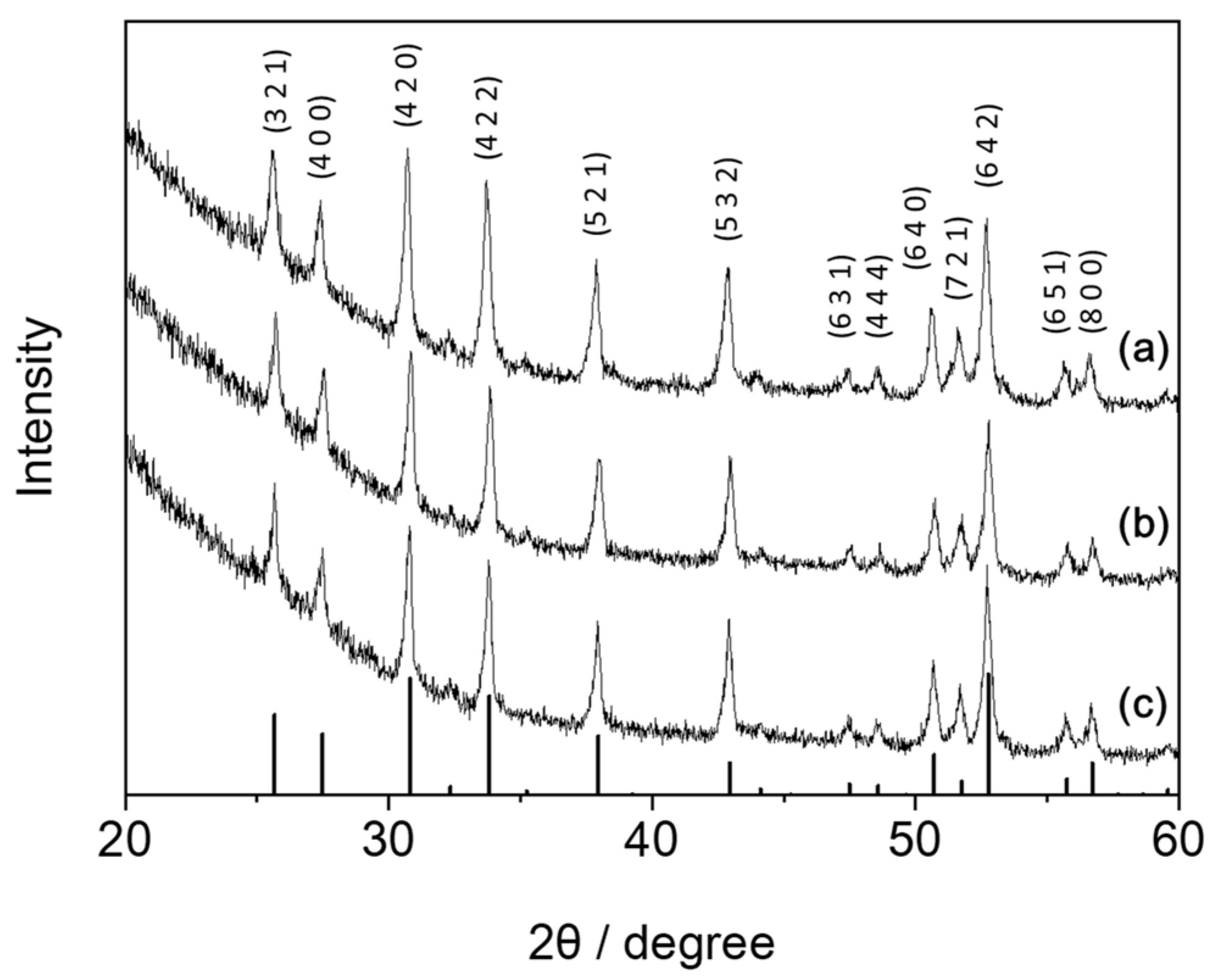
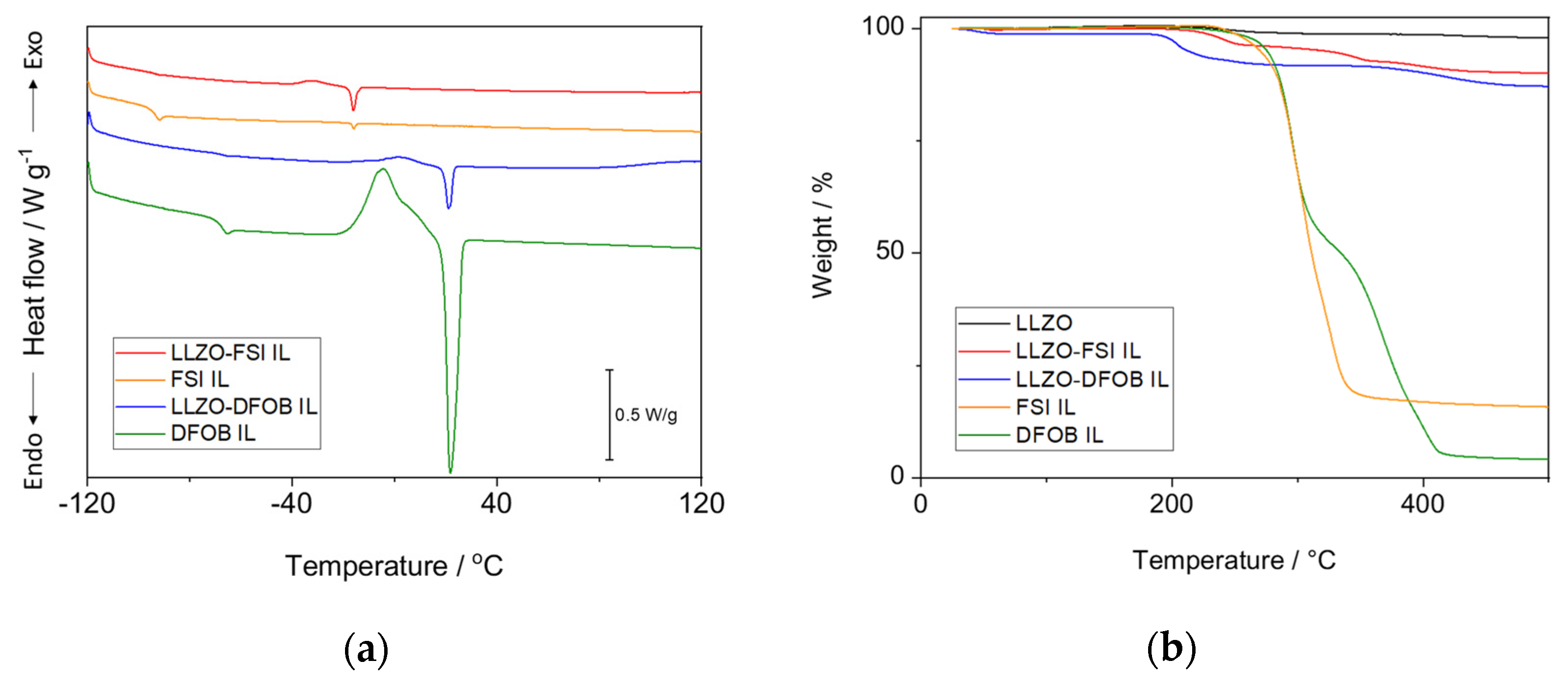
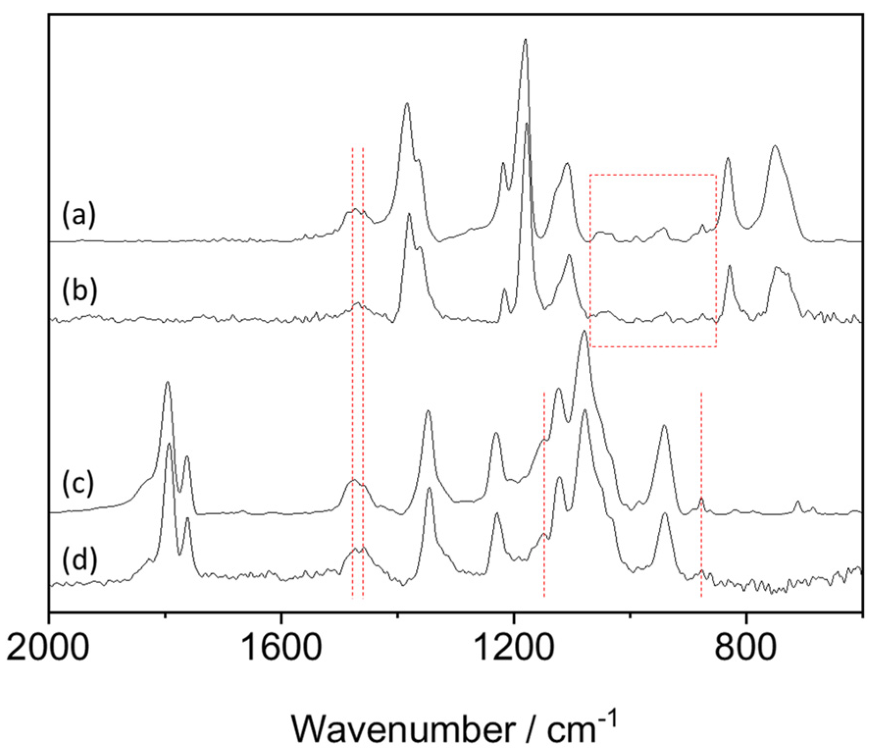
3.1. Fundamental Properties of LLZO–IL Composites

Figure 2 is the XRD pattern of LLZO and its composites containing 15 wt% ILs. The diffraction pattern of Al-doped LLZO, taken from the reference [27], is also shown as a reference. The slope in the background at lower angles is due to Kapton. In the pattern of pristine LLZO, typical signals of a cubic phase of Al-doped LLZO are observed. It is known that the cubic structure of LLZO needs to be maintained to realize its high ionic conductivity [28]. The XRD patterns of LLZO–IL composites are identical to that of the pristine LLZO, confirming the crystalline structure of LLZO is stable and not affected by the presence of the ILs. This suggests that unfavorable reactions, such as dissolution of metal cations by the ILs, did not occur during the synthesis of the composites.
Figure 3 shows thermal properties of the LLZO–IL composites. As shown in the DSC curve of FSI IL (orange) and its LLZO composite (red), a glass transition temperature (Tg) of pure FSI IL was around −95 °C and remained the same even when the IL was mixed with LLZO. A melting temperature (Tm) of FSI IL was observed at a constant temperature of c.a. −15 °C regardless of the presence of LLZO. With the Tm, however, the peak intensity was more pronounced with LLZO. The change in peak intensity but not in peak position suggests that the degree of structural order of the IL is enhanced in the LLZO composites, which is most likely due to physical interactions between LLZO and FSI IL (will be discussed subsequently), but this interaction does not affect the dissociation rate of the IL. This increase was not observed when DFOB IL was used. Both Tg and Tm assigned to DFOB IL were observed at the same temperatures and became minor when the IL was mixed with LLZO.
Results of TGA are shown in Figure 3b. The curve in the range of 500–700 °C is not shown because the weight change in this range was negligible (<0.01 wt% per min). As reported in the literature, LLZO is thermally stable and its decomposition temperature is above 1000 °C [7]. Similarly, a huge weight loss was not observed in the curve of the pristine LLZO (black), but slight weight losses were visible at 200 and 400 °C (see Figure S1), which are expected to be assigned to the decomposition of impurities such as La(NO3)3 [29]. For the composites with 15 wt% FSI IL and DFOB IL, weight losses at 500 °C were found to be 9.8% and 12.7%, respectively. These losses are expected to be due to the decomposition of the organic components, i.e., ILs. However, the weight losses were observed at 200 and 400 °C (see red and blue curves), which were different from the decomposition temperatures of pure ILs. They are rather similar to those of LLZO. This fact suggests that reactive gases, such as HNO3 and NOx [30], are formed due to the presence of a trace of metal nitrate in LLZO and cause the decomposition of ILs at lower temperatures. Although the decomposition temperatures of LLZO–IL composites are lower compared to that of pure LLZO, the composites can be confirmed to be stable in the temperature range of battery operation.
In Figure 4, ATR-FTIR spectra of the composites are shown. The samples are pristine FSI IL, LLZO–15 wt% FSI IL, pristine DFOB IL, and LLZO–15 wt% DFOB IL. In the upper two curves for the materials with FSI anion, strong signals are attributable as follows: 1383, 1364, 1218, and 1180 cm−1 for SO2 str; 1106 cm−1 for S-N-S str; 831 and 750 cm−1 for S-F str [31,32]. The minor signals at 1474 and 1457 cm−1 (broken red lines) as well as those in the red square are assigned to the cation structure [33]. A change in the peak shape was observed at 750 cm−1. From this signal, it is possible to estimate the ratio of cisoid or transoid conformers of FSI because the FSI anions with cis and trans conformations exhibit their band at 730 and 750 cm−1, respectively [31]. In the case of pure FSI IL, the peak around these frequencies can be accurately fitted by two Gaussian peaks as shown in Figure S2. The peak at around 750 cm−1 was more intense compared with that at around 730 cm−1. When LLZO was present, a broad signal with multiple peak tops was observed. In this case, the peak intensity at 730 cm−1 was slightly higher than that at 750 cm−1. This suggests that the cis conformer is major in the LLZO–FSI IL composites while the trans conformer is dominant in the pure FSI IL. This change confirms the presence of physical interaction between LLZO and FSI IL as discussed for DSC. The curves for the pristine DFOB IL and its composites with LLZO are shown in the bottom. The peaks are assigned as follows: 1795 and 1761 cm−1 for C=O str; 1347 cm−1 for C-C str and C-O str; 1229 cm−1 for C-C bend and CO str; 1121 and 1076 cm−1 for B-F str, and 941 cm−1 for B-O str. The peaks related to the cation structures were observed at 1473, 1457, 1150, and 876 cm−1. In the case of LLZO–DFOB IL composite, noticeable change of the spectra in terms of peak position and intensity was not observed.

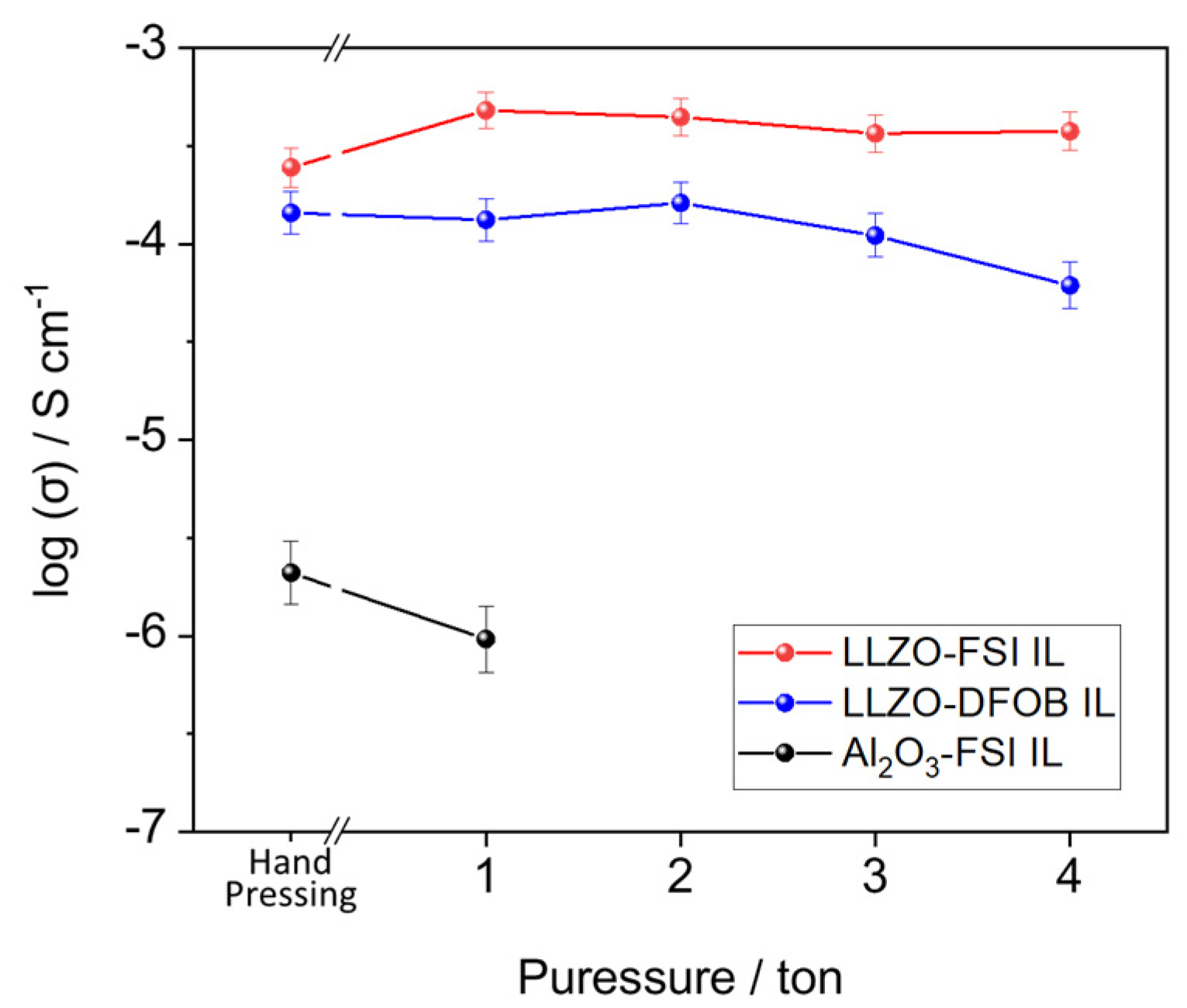
3.2. Ionic Conductivity of LLZO–IL Composites

An error of our set up of ionic conductivity measurement was estimated to be 2.9% from repeated measurements using three cells having LLZO–15 wt% FSI IL as a standard material. This value was used to provide error bars in the figures in this section. Ionic conductivity was measured by changing three different factors: pressure for the pellet preparation (1–4 tons and also hand press), exposure time (1–24 h), and temperatures (room temperature–100 °C). Thickness of pellets prepared at different pressures is summarized in Table S1. Figure 5 reports the ionic conductivity of LLZO–IL composites pressed with different pressure, and that of Al2O3–FSI IL composites is shown as a reference. The concentration of the ILs was fixed to be 15 wt%. The Nyquist plot of pristine LLZO, pressed with 1 ton, is shown in the supplementary information (Figure S3). One large semicircle was observed and the ionic conductivity estimated from the diameter of the semicircle was 1.1 × 10⁻⁹ S cm−1. When LLZO was integrated with the ILs, the conductivity values increased to the order of 10−4 S cm−1 as shown in Figure 5 even when the pellets were prepared by hand pressing. In these cases, semicircle was not observed in the Nyquist plots (Figure S4), confirming that the grain boundary resistances were eliminated by ILs. The ionic conductivity of the LLZO composites was slightly lower compared with that of the pristine ILs (3.5 × 10⁻³ S cm−1 for FSI IL and 0.7 × 10⁻³ S cm−1 for DFOB IL). The conductivity values of our LLZO–IL composites are comparable to other LLZO composites with conventional ILs such as N-butyl-N-methylpyrrolidinium bis(trifluoromethanesulfonyl)imide ([Py14][TFSI]) as summarized in Table 1 and even with the composites based on LAGP containing 50 wt% IL.
When FSI IL was added to LLZO, the conductivity increased by making the pellet with 1 ton instead of hand press, and the increased value was maintained until the pressure was increased to 4 ton. In the case of LLZO–DFOB IL composites, the conductivity values did not increase even when the pressure was increased to 2 ton, and instead they rather decreased above 3 ton, which suggests the bleed out of DFOB IL. This was not observed in the case of FSI IL, which is probably because of the presence of physical interaction among the components. In the DSC curve of LLZO–FSI IL (Figure 3a), the melting peak arising from FSI IL was intense compared with that in the DSC curve of pristine ILs, suggesting enhanced structural order of the IL in the composites. In addition, in the infrared spectroscopy, the dominant conformer of FSI anion was found to change from trans to cis with the presence of LLZO. Taking all these results into account, we consider that FSI anion interacts more with LLZO than DFOB anion. The reference sample based on a non-ion conductive ceramic, specifically Al2O3, and 15 wt% FSI IL exhibited ionic conductivity around 10−6 S cm−1, which suggests not all combinations of ceramic and ILs are suitable as hybrid electrolytes.
Stability of the composites against time exposure was evaluated by monitoring ionic conductivity of LLZO–FSI IL and LLZO–DFOB IL composites, pressed with 1 ton for the preparation of their pellets, for 24 h. As shown in Figure S5, the conductivity was constant throughout the course of measurements, suggesting absence of unfavorable side reactions, such as bleed out of the ILs, phase separation of composites, and decomposition of the ILs. The conductivity decreased by increasing the pressure for pellet preparation but was constant with time exposure, suggesting that the bleed out of DFOB IL is not spontaneous and occurs only when the pellet is pressed with a high pressure. Figure 6 shows temperature dependency of the ionic conductivity of LLZO–IL composites. The conductivities at 15 °C, 4.8 × 10⁻⁴ S cm−1 for LLZO–FSI IL and 1.9 × 10⁻⁴ S cm−1 for LLZO–DFOB IL, increased to 3.8 × 10⁻³ S cm−1 and 1.7 × 10⁻³ S cm−1 at 100 °C, respectively. The conductivity value of 1.0 × 10⁻³ S cm−1, which is a preferred value for battery applications, was achieved at around room temperature in the case of the LLZO–FSI IL composite.

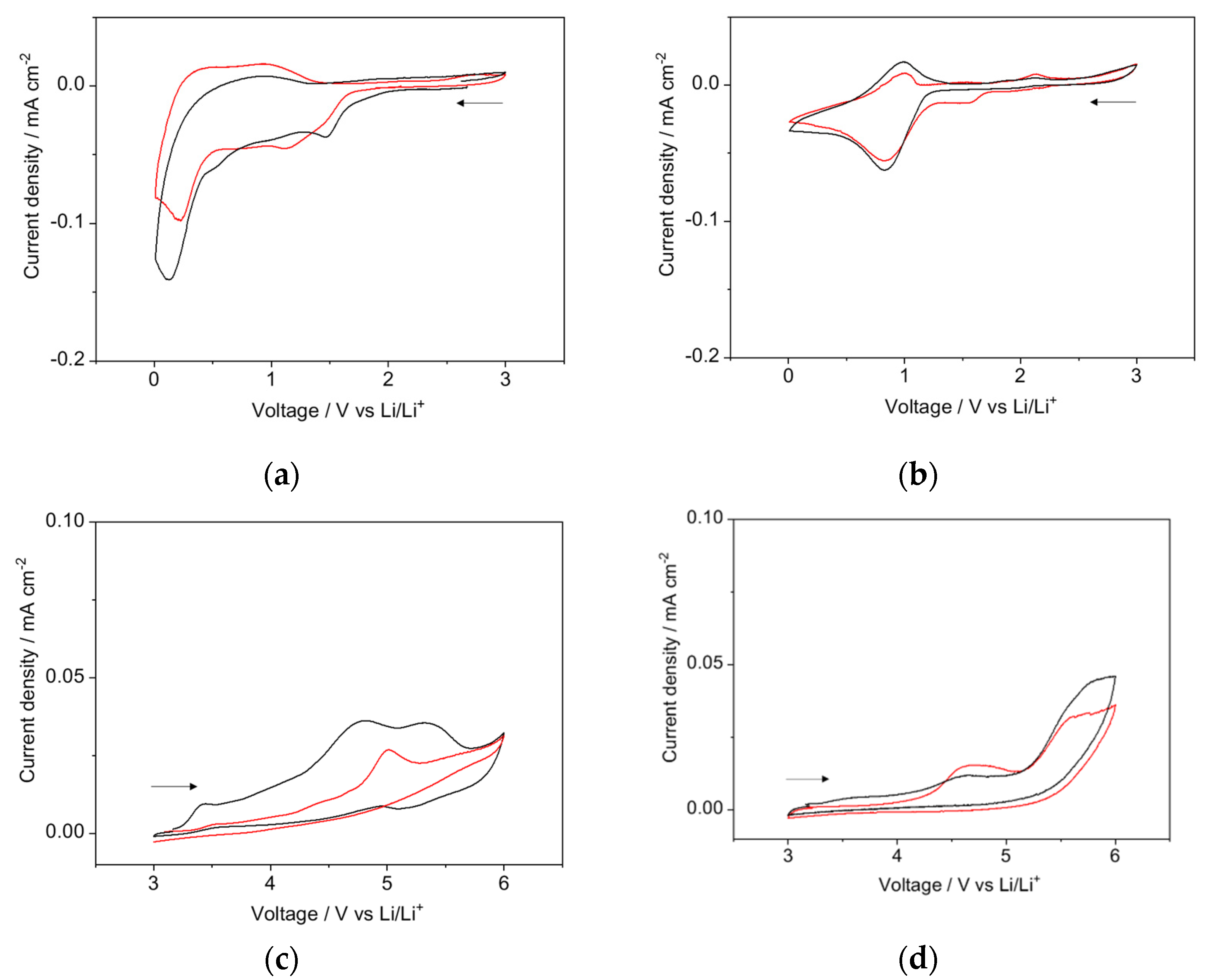
3.3. Electrochemical Stability of LLZO–IL Composites

The ternary composites of LLZO with either FSI IL or DFOB IL containing their corresponding lithium salt, namely LiFSI or LiDFOB, in ratio of IL:Li salt = 9:1 in mol, were prepared in addition to the binary composites of LLZO and ILs. Figure 7 summarizes the CV of these four composites. In the cathodic scan (OCV to 0.01 V vs. Li/Li+) of LLZO–FSI IL composites with and without LiFSI (Figure 7a), an increase in the reduction current was observed from 1.8 V vs. Li/Li+ due to the decomposition of FSI anion as discussed in the literature [24]. This current was suppressed in the successive cycles (Figure S6), suggesting the formation of a passivation layer on Super P surface. The reduction current below 0.5 V vs. Li/Li+ arose from the lithium intercalation to Super P. This current density decreased during successive cycling when LiFSI was absent. When LiFSI was present in the composite, however, the currents associated with lithium intercalation as well as lithium de-intercalation in the reverse scan were found to be constant from the 2nd to the 4th cycle. This confirms the lithium intercalation/de-intercalation is reproducible in the case of the ternary composite made of LLZO, FSI IL, and LiFSI. In the anodic scan from OCV to 6.0 V vs. Li/Li+, the current increase began at 3.2 V vs. Li/Li+ and current density reached 0.01 mA cm−2 at 3.9 V vs. Li/Li+ in the case of LLZO–FSI IL binary composites. This oxidation current was suppressed with the presence of LiFSI. In this case, the current density was less than 0.01 mA cm−2 until 4.7 V.
For the composites with DFOB IL, the reduction current was observed around 0.9 V vs. Li/Li+. A current due to the reduction of DFOB was observed at 1.4 V vs. Li/Li+ when a similar IL with DFOB anion, namely N-methoxyethyl-N-methylpiperidinium DFOB, was added to carbonate-based electrolyte [23], while when this anion was combined with N-alkyl-N-methylpyrrolidinium, the reduction current was observed at 0.4 V vs. Li/Li+ [34]. Therefore, the peak at 0.9 V vs. Li/Li+ is expected to be due to the reduction of the DFOB anions. In the case of the composites with DFOB IL, a stable lithium intercalation/de-intercalation was not observed regardless of the presence of LiDFOB (see Figure S6). Because of the better ionic conductivity and the ability of constant lithium intercalation/de-intercalation, LLZO–FSI IL doped with LiFSI was used for the galvanostatic charge–discharge analysis.

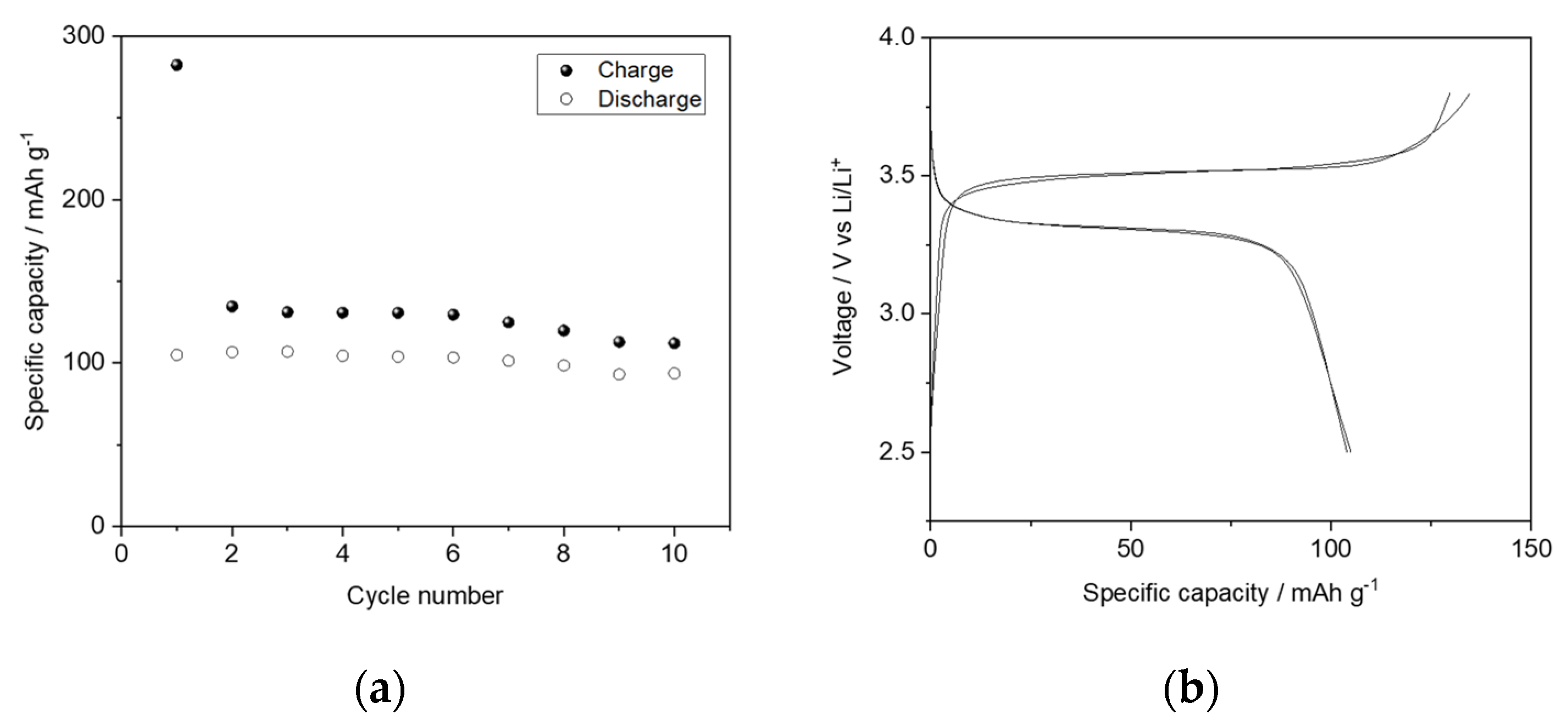
3.4. Performance of Battery with LLZO–IL Composites

Using the ternary composite of LLZO, FSI IL, and LiFSI as an electrolyte, which exhibits better ionic conductivity, ASS lithium metal cells were prepared. Figure 8 shows the galvanostatic cycling performance of LiFePO4|Li cycled at C/20. The cell retains a specific capacity higher than 100 mAh g−1 throughout 10 cycles. A retention rate of 1st/10th discharge capacity was found to be 89.5%. As shown in Figure 8b, the cell exhibited a flat voltage profile, which is characteristic of LiFePO4.

4. Conclusions

Organic–inorganic hybrid materials based on LLZO and either FSI IL or DFOB IL were prepared. From TGA analysis, both composites were confirmed to be stable in the temperature range where batteries are expected to work. In DSC and ATR-FTIR analyses, it was suggested that FSI IL formed a physical interaction with LLZO, while evidence of interactions was not observed in the case of DFOB IL. In the latter case, its ionic conductivity decreased when the pellet was pressed with a pressure higher than 2 ton, which is probably due to a bleed out of DFOB IL. With respect to the electrolyte pellets prepared with 1 ton, the higher conductivities were found for LLZO–FSI IL (4.8 × 10⁻⁴ S cm−1 at 15 °C) and the conductivity of 10−3 S cm−1 was achieved at room temperature, which cannot be achieved through the cold pressing of pristine LLZO. In addition to this, a constant lithium intercalation/de-intercalation behavior was observed during the CV of LLZO–FSI IL doped with LiFSI. For this reason, the ASS lithium metal cells, having the composition LiFePO4|LLZO–FSI IL–LiFSI|Li, were assembled. The cell exhibited a specific capacity higher than 100 mAh g−1 throughout 10 cycles when the cell was cycled at C/20. These results confirm that the addition of ILs effectively reduces the grain boundary resistance between LLZO particles. By using ILs as a conductive binder for LLZO, a battery with favorable performance can be prepared through a simple cold-pressing procedure.

Supplementary Materials

The following supporting information can be downloaded at: https://www.mdpi.com/article/10.3390/app12147318/s1, Figure S1: Enlarged TGA curve of pristine LLZO; Table S1: Thickness of the pellet of LLZO–FSI IL and LLZO–DFOB IL; Figure S2: Gauss curve fitting of ATR-FTIR spectra of pure FSI IL and LLZO–FSI IL composite, Figure S3: Impedance spectrum of pure LLZO pressed with 1 ton; Figure S4: Nyquist plot of impedance spectra; Figure S5: Change of the ionic conductivity of LLZO–FSI IL and LLZO–DFOB IL composites versus time; Figure S6: CV of LLZO–FSI IL and LLZO–DFOB IL composites with and without a corresponding lithium salt.

Author Contributions

Conceptualization, A.T. and M.A.N.; methodology, A.T.; investigation, R.R. and L.M.; data curation, A.T. and R.R.; writing—original draft preparation, A.T.; writing—review and editing, L.M. and M.A.N.; supervision, M.A.N.; funding acquisition, A.T. and M.A.N. All authors have read and agreed to the published version of the manuscript.

Funding

This research was funded by Sapienza University of Rome, Avvio alla Ricerca 2020 (AR220172B8AEEAFE) for “Design of multifunctional surface on inorganic ceramic solid electrolytes by using ionic liquids” (A.T.) and Ateneo 2020 (RM120172B3B81486) for “Ionic Liquid-based electrolytes for Energy Storage devices (ILES)” (M.A.N.).

Acknowledgments

Authors acknowledge Giorgio Amico, the Department of Physics, Sapienza University of Rome for his technical support during fabrication of home-made ASS cells.

Conflicts of Interest

The authors declare no conflict of interest. The funders had no role in the design of the study; in the collection, analyses, or interpretation of data; in the writing of the manuscript, or in the decision to publish the results.

References

  1. Chen, Y.; Wen, K.; Chen, T.; Zhang, X.; Armand, M.; Chen, S. Recent progress in all-solid-state lithium batteries: The emerging strategies for advanced electrolytes and their interfaces. Energy Storage Mater. 2020, 31, 401–433. [Google Scholar] [CrossRef]
  2. Gao, Z.; Sun, H.; Fu, L.; Ye, F.; Zhang, Y.; Luo, W.; Huang, Y. Promises, Challenges, and Recent Progress of Inorganic Solid-State Electrolytes for All-Solid-State Lithium Batteries. Adv. Mater. 2018, 30, e1705702. [Google Scholar] [CrossRef] [PubMed]
  3. Yu, W.; Xue, C.; Hu, B.; Xu, B.; Li, L.; Nan, C.-W. Oxygen- and dendrite-resistant ultra-dry polymer electrolytes for solid-state Li–O2 batteries. Energy Storage Mater. 2020, 27, 244–251. [Google Scholar] [CrossRef]
  4. Zhu, H.; MacFarlane, D.R.; Pringle, J.M.; Forsyth, M. Organic Ionic Plastic Crystals as Solid-State Electrolytes. Trends Chem. 2019, 1, 126–140. [Google Scholar] [CrossRef] [Green Version]
  5. Famprikis, T.; Canepa, P.; Dawson, J.A.; Islam, M.S.; Masquelier, C. Fundamentals of inorganic solid-state electrolytes for batteries. Nat. Mater. 2019, 18, 1278–1291. [Google Scholar] [CrossRef]
  6. Betz, J.; Bieker, G.; Meister, P.; Placke, T.; Winter, M.; Schmuch, R. Theoretical versus Practical Energy: A Plea for More Transparency in the Energy Calculation of Different Rechargeable Battery Systems. Adv. Energy Mater. 2018, 9, 1803170. [Google Scholar] [CrossRef]
  7. Wu, Y.; Wang, S.; Li, H.; Chen, L.; Wu, F. Progress in thermal stability of all-solid-state-Li-ion-batteries. InfoMat 2021, 3, 827–853. [Google Scholar] [CrossRef]
  8. Nam, Y.J.; Oh, D.Y.; Jung, S.H.; Jung, Y.S. Toward practical all-solid-state lithium-ion batteries with high energy density and safety: Comparative study for electrodes fabricated by dry- and slurry-mixing processes. J. Power Sources 2018, 375, 93–101. [Google Scholar] [CrossRef]
  9. Viallet, V.; Seznec, V.; Hayashi, A.; Tatsumisago, M.; Pradel, A. Glasses and Glass-Ceramics for Solid-State Battery Applications; Springer: Berlin/Heidelberg, Germany, 2019; pp. 1697–1754. [Google Scholar] [CrossRef]
  10. Chen, X.; Guan, Z.; Chu, F.; Xue, Z.; Wu, F.; Yu, Y. Air-stable inorganic solid-state electrolytes for high energy density lithium batteries: Challenges, strategies, and prospects. InfoMat 2021, 4, e12248. [Google Scholar] [CrossRef]
  11. Xu, Q.; Tsai, C.-L.; Song, D.; Basak, S.; Kungl, H.; Tempel, H.; Hausen, F.; Yu, S.; Eichel, R.-A. Insights into the reactive sintering and separated specific grain/grain boundary conductivities of Li1.3Al0.3Ti1.7(PO4)3. J. Power Sources 2021, 492, 229631. [Google Scholar] [CrossRef]
  12. Liu, M.; Cheng, Z.; Ganapathy, S.; Wang, C.; Haverkate, L.A.; Tułodziecki, M.; Unnikrishnan, S.; Wagemaker, M. Tandem Interface and Bulk Li-Ion Transport in a Hybrid Solid Electrolyte with Microsized Active Filler. ACS Energy Lett. 2019, 4, 2336–2342. [Google Scholar] [CrossRef] [Green Version]
  13. Fan, L.-Z.; He, H.; Nan, C.-W. Tailoring inorganic–polymer composites for the mass production of solid-state batteries. Nat. Rev. Mater. 2021, 6, 1003–1019. [Google Scholar] [CrossRef]
  14. de la Torre-Gamarra, C.; Appetecchi, G.B.; Ulissi, U.; Varzi, A.; Varez, A.; Passerini, S. Na3Si2Y0.16Zr1.84PO12-ionic liquid hybrid electrolytes: An approach for realizing solid-state sodium-ion batteries? J. Power Sources 2018, 383, 157–163. [Google Scholar] [CrossRef]
  15. Kim, H.W.; Manikandan, P.; Lim, Y.J.; Kim, J.H.; Nam, S.C.; Kim, Y. Hybrid solid electrolyte with the combination of Li7La3Zr2O12 ceramic and ionic liquid for high voltage pseudo-solid-state Li-ion batteries. J. Mater. Chem. A 2016, 4, 17025–17032. [Google Scholar] [CrossRef]
  16. Kim, K.; Park, J.; Jeong, G.; Yu, J.S.; Kim, Y.C.; Park, M.S.; Cho, W.; Kanno, R. Rational Design of a Composite Electrode to Realize a High-Performance All-Solid-State Battery. ChemSusChem 2019, 12, 2637–2643. [Google Scholar] [CrossRef] [PubMed]
  17. Armand, M.; Endres, F.; MacFarlane, D.R.; Ohno, H.; Scrosati, B. Ionic-liquid materials for the electrochemical challenges of the future. Nat. Mater. 2009, 8, 621–629. [Google Scholar] [CrossRef]
  18. Pervez, S.A.; Kim, G.; Vinayan, B.P.; Cambaz, M.A.; Kuenzel, M.; Hekmatfar, M.; Fichtner, M.; Passerini, S. Overcoming the Interfacial Limitations Imposed by the Solid-Solid Interface in Solid-State Batteries Using Ionic Liquid-Based Interlayers. Small 2020, 16, e2000279. [Google Scholar] [CrossRef] [Green Version]
  19. Zhang, Z.; Zhang, L.; Liu, Y.; Wang, H.; Yu, C.; Zeng, H.; Wang, L.M.; Xu, B. Interface-Engineered Li7La3Zr2O12-Based Garnet Solid Electrolytes with Suppressed Li-Dendrite Formation and Enhanced Electrochemical Performance. ChemSusChem 2018, 11, 3774–3782. [Google Scholar] [CrossRef] [Green Version]
  20. Xiong, S.; Liu, Y.; Jankowski, P.; Liu, Q.; Nitze, F.; Xie, K.; Song, J.; Matic, A. Design of a Multifunctional Interlayer for NASCION-Based Solid-State Li Metal Batteries. Adv. Funct. Mater. 2020, 30, 2001444. [Google Scholar] [CrossRef] [Green Version]
  21. Navarra, M.A.; Fujimura, K.; Sgambetterra, M.; Tsurumaki, A.; Panero, S.; Nakamura, N.; Ohno, H.; Scrosati, B. New Ether-functionalized Morpholinium- and Piperidinium-based Ionic Liquids as Electrolyte Components in Lithium and Lithium-Ion Batteries. ChemSusChem 2017, 10, 2496–2504. [Google Scholar] [CrossRef]
  22. Kerr, R.; Mazouzi, D.; Eftekharnia, M.; Lestriez, B.; Dupré, N.; Forsyth, M.; Guyomard, D.; Howlett, P.C. High-Capacity Retention of Si Anodes Using a Mixed Lithium/Phosphonium Bis(fluorosulfonyl)imide Ionic Liquid Electrolyte. ACS Energy Lett. 2017, 2, 1804–1809. [Google Scholar] [CrossRef]
  23. Tsurumaki, A.; Branchi, M.; Rigano, A.; Poiana, R.; Panero, S.; Navarra, M.A. Bis(oxalato)borate and difluoro(oxalato)borate-based ionic liquids as electrolyte additives to improve the capacity retention in high voltage lithium batteries. Electrochim. Acta 2019, 315, 17–23. [Google Scholar] [CrossRef]
  24. Tsurumaki, A.; Ohno, H.; Panero, S.; Navarra, M.A. Novel bis(fluorosulfonyl)imide-based and ether-functionalized ionic liquids for lithium batteries with improved cycling properties. Electrochim. Acta 2019, 293, 160–165. [Google Scholar] [CrossRef]
  25. Moreno, J.S.; Deguchi, Y.; Panero, S.; Scrosati, B.; Ohno, H.; Simonetti, E.; Appetecchi, G.B. N-Alkyl-N-ethylpyrrolidinium cation-based ionic liquid electrolytes for safer lithium battery systems. Electrochim. Acta 2016, 191, 624–630. [Google Scholar] [CrossRef]
  26. Montanino, M.; Alessandrini, F.; Passerini, S.; Appetecchi, G.B. Water-based synthesis of hydrophobic ionic liquids for high-energy electrochemical devices. Electrochim. Acta 2013, 96, 124–133. [Google Scholar] [CrossRef]
  27. Buschmann, H.; Dölle, J.; Berendts, S.; Kuhn, A.; Bottke, P.; Wilkening, M.; Heitjans, P.; Senyshyn, A.; Ehrenberg, H.; Lotnyk, A.; et al. Structure and dynamics of the fast lithium ion conductor “Li7La3Zr2O12”. Phys. Chem. Chem. Phys. 2011, 13, 19378–19392. [Google Scholar] [CrossRef] [Green Version]
  28. Shin, R.-H.; Son, S.I.; Han, Y.S.; Kim, Y.D.; Kim, H.-T.; Ryu, S.-S.; Pan, W. Sintering behavior of garnet-type Li7La3Zr2O12-Li3BO3 composite solid electrolytes for all-solid-state lithium batteries. Solid State Ion. 2017, 301, 10–14. [Google Scholar] [CrossRef]
  29. Yang, S.H.; Kim, M.Y.; Kim, D.H.; Jung, H.Y.; Ryu, H.M.; Han, J.H.; Lee, M.S.; Kim, H.-S. Ionic conductivity of Ga-doped LLZO prepared using Couette–Taylor reactor for all-solid lithium batteries. J. Ind. Eng. Chem. 2017, 56, 422–427. [Google Scholar] [CrossRef]
  30. Mekhemer, G.A.H.; Balboul, B.A.A. Thermal genesis course and characterization of lanthanum oxide. Colloids Surf. A Physicochem. Eng. Asp. 2001, 181, 19–29. [Google Scholar] [CrossRef]
  31. Palumbo, O.; Trequattrini, F.; Cimini, A.; Tsurumaki, A.; Navarra, M.A.; Paolone, A. Inter- and Intramolecular Interactions in Ether-Functionalized Ionic Liquids. J. Phys. Chem. B 2021, 125, 2380–2388. [Google Scholar] [CrossRef]
  32. Li, L.; Zhou, S.; Han, H.; Li, H.; Nie, J.; Armand, M.; Zhou, Z.; Huang, X. Transport and Electrochemical Properties and Spectral Features of Non-Aqueous Electrolytes Containing LiFSI in Linear Carbonate Solvents. J. Electrochem. Soc. 2011, 158, A74. [Google Scholar] [CrossRef]
  33. Tsurumaki, A.; Trequattrini, F.; Palumbo, O.; Panero, S.; Paolone, A.; Navarra, M.A. The effect of ether-functionalisation in ionic liquids analysed by DFT calculation, infrared spectra, and Kamlet-Taft parameters. Phys. Chem. Chem. Phys. 2018, 20, 7989–7997. [Google Scholar] [CrossRef] [PubMed]
  34. Allen, J.L.; McOwen, D.W.; Delp, S.A.; Fox, E.T.; Dickmann, J.S.; Han, S.-D.; Zhou, Z.-B.; Jow, T.R.; Henderson, W.A. N-Alkyl-N-methylpyrrolidinium difluoro(oxalato)borate ionic liquids: Physical/electrochemical properties and Al corrosion. J. Power Sources 2013, 237, 104–111. [Google Scholar] [CrossRef]
Figure 1. Chemical structure of FSI IL and DFOB IL.
Applsci 12 07318 g001
Figure 2. XRD curves of (a) LLZO and its composites with (b) 15 wt% FSI IL and (c) 15 wt% DFOB IL. The reference pattern (bar) is taken from the reference [27].
Applsci 12 07318 g002
Figure 3. (a) DSC and (b) TGA curves of LLZO–15 wt% FSI IL (red), LLZO–15 wt% DFOB IL (blue), pristine FSI IL (orange), and pristine DFOB IL (green).
Applsci 12 07318 g003
Figure 4. ATR-FTIR spectra of (a) pristine FSI IL, (b) LLZO–15 wt% FSI IL, (c) pristine DFOB IL, and (d) LLZO–15 wt% DFOB IL.
Applsci 12 07318 g004
Figure 5. Ionic conductivity of LLZO–15 wt% FSI IL composite (red) and LLZO–15 wt% DFOB IL composite (blue) as a function of the pressure to make electrolyte pellets. The conductivity of Al2O3-15 wt% FSI IL composites is also shown as a reference (black).
Applsci 12 07318 g005
Figure 6. Arrhenius plot of ionic conductivity of LLZO–15 wt% FSI IL composite (red) and LLZO–15 wt% DFOB IL composite (blue), pressed with 1 ton.
Applsci 12 07318 g006
Figure 7. CV voltammetry of (a,c) LLZO–FSI IL and (b,d) LLZO–DFOB IL composites with (red) and without (black) lithium salt in the ranges of (a,b) 3–0.01 V vs. Li/Li+ and (c,d) 3–6 V vs. Li/Li+. The arrows indicate the starting point and direction of the sweeps.
Applsci 12 07318 g007
Figure 8. (a) Specific capacity during the charge–discharge cycle of LiFePO4|Li cell having LLZO–FSI IL–LiFSI as the electrolyte and (b) its voltage profile during the 2nd and 5th cycles.
Applsci 12 07318 g008
Table 1. Composition, preparation procedure, and ionic conductivity of different hybrid materials based on SE and IL additive.
SEAdditiveSE:Additive Ratio
in Weight
Mixing
Procedure
Pressure
for Pellet
Conductivity
(S/cm)
Ref.
r.t.60 °C
Li6.24La3Zr2Al0.24O11.98FSI IL85:15mortar mixing1 ton4.8 × 10−4 c2.1 × 10−3- d
Li6.24La3Zr2Al0.24O11.98DFOB IL85:15mortar mixing1 ton1.9 × 10−4 c1.0 × 10−3- d
Li7La3Zr2O12[Py14][TFSI]/LiTFSI a
(19:1 wt/wt)
80:20ball milling
(40 rpm/1 h)
2 ton4.0 × 10−41.6 × 10⁻³[15]
Li6.75La3Zr1.75Ta0.25O12[Py14][TFSI] a86:14mortar mixing15 MPa6.7 × 10−4~3 × 10⁻³[19]
Li1.5Al0.5Ge1.5(PO4)3[bmim][FSI]/LiFSI b
(9/1)
50:50ball milling
(200 rpm/0.5 h)
-~2 × 10⁻³~5 × 10⁻³[20]
a N-butyl-N-methylpyrrolidinium bis(trifluoromethanesulfonyl)imide; b 1-butyl-3-methylimidazolium bis(fluorosulfonyl)imide; c measured at 15 °C; d present study.
Publisher’s Note: MDPI stays neutral with regard to jurisdictional claims in published maps and institutional affiliations.

