Article

Identification of Multimodal Dynamic Characteristics of a Decurrent Tree with Application to a Model-Scale Wind Tunnel Study

1
Key Laboratory of Building Safety and Energy Efficiency of the Ministry of Education, Hunan University, Changsha 410082, China
2
College of Civil Engineering, Hunan University, Changsha 410082, China
3
Boundary Layer Wind Tunnel Laboratory, Faculty of Engineering, Western University, London, ON N6A 5B9, Canada
4
Department of Civil Engineering, Tamkang University, Taipei 25137, Taiwan, China
*
Author to whom correspondence should be addressed.
Appl. Sci. 2022, 12(15), 7432; https://doi.org/10.3390/app12157432
Submission received: 30 April 2022 / Revised: 15 July 2022 / Accepted: 21 July 2022 / Published: 24 July 2022

Abstract

:
Wind tunnel tests of scaled model trees provide an effective approach for understanding fluctuating wind loading and wind-induced response of trees. For decurrent trees, vague multimodal dynamic characteristics and ineffective estimation of leaf mass are two of the main obstacles to developing aeroelastic models. In this study, multimodal dynamic characteristics of the decurrent tree are identified by field measurements and finite element models (FEM). It was found that the number of branches swaying in phase determines the magnitude of effective mass fraction of branch modes. The frequencies of branch modes with larger effective mass fraction were considered as a reference for an aeroelastic model. In addition, an approach to estimate leaf mass without destruction was developed by comparing trunk frequency between field measurements and FEM. Based on these characteristics of the prototype, the scaled, aeroelastic model was constructed and assessed. It was found that the mismatch of leaf stiffness between the model and the prototype leads to mismatch of leaf streamlining and damping between them. The Vogel exponent associated with leaf streamlining provides a possible way to ensure consistency of leaf stiffness between the model and prototype.

1. Introduction

Understanding wind loads and damage to trees in forests is important for many reasons, most recently with respect to identifying the intensity of tornadoes [1,2]. The turbulent nature of the fluctuating wind indicates that wind-induced response and wind loading of trees are not steady but rapidly fluctuate [3]. Compared with obvious challenges in field measurements, wind tunnel tests of scaled, aeroelastic model trees is a more effective approach for studying the fluctuating load and response on trees in forests [4]. However, vague multimodal dynamic characteristics and ineffective estimation of leaf mass are two of the main obstacles to developing aeroelastic models. This is mainly because multiple branches determine that multimodal dynamics associated with branches play a key role in the dynamic process, and the aerodynamics of trees are mainly determined by leaves. Therefore, we explored multimodal dynamic characteristics of a decurrent tree, leaf mass estimation, and complete crown characteristics and model assessment of the Hao’ model [5] in this study.
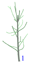
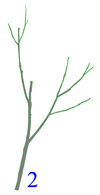
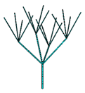
According to the form of the crown, trees can be divided into two categories: decurrent and excurrent trees. A typical decurrent tree is shown in Figure 1a, which is characterized by a shorter trunk and a crown supported by radial branches. In the extreme cases, the decurrent trees can have only spreading branches with nearly no central trunk. The excurrent trees, on the other hand, have a central trunk (Figure 1b), as well as lateral branches. Structurally, the central trunk of an excurrent tree looks like a “pillar”, on top of which the lateral branches, or the “cantilevers”, are fixed.
Branched trees have a complex organization of modes with high modal density and spatial localization [6,7], where high modal density occurs when most of the natural frequencies associated with the branches are in a narrow frequency range. Spatial localization is defined as the combinations of spatial coordinates of branches and the trunk at their natural frequencies. This means that some branch modes have either a localized resonance or a global resonance [8]. Localized resonance will not generally break the trunk or anchorage system, while global resonance affects the global dynamic response of trees. So far, most studies regarding the multimodal behaviour of trees have focused on the effect of high modal density and distinct branch deformation on the wind energy dissipation in trees. For example, multiple mass damping [9,10], multiple resonance damping [11], and branch damping [7] have been studied. For excurrent trees, aeroelastic models usually neglect the contribution derived from branches [12]. However, this is not the case for decurrent trees because of crown deformation determined by branches. A lack of studies regarding the contribution of branch modes to dynamic response makes it difficult to model the dynamic characteristics of the aeroelastic model of a decurrent tree. Therefore, in this paper, the first objective is to quantify the contribution of branch modes in the dynamic processes and determine which branch modes contribute the most.
It should be noted that it is not practical to track each branch by setting sensors on each one in field measurements. In contrast, the finite element method provides an effective approach to characterize the modes generated from branches moving in a complex manner [10,13,14]. Using the FEM, leaf clusters can be considered as a lumped mass attached to branches [15,16], or included in the mass of the primary branch by increasing its density proportionately [14,17,18,19,20], or simply neglected [6,21]. The leaf mass in such models is usually vaguely defined and estimated empirically. Although this may have a limited effect on tree dynamics that depend on the form and morphology of tree and branches [10], accurate estimation of leaf mass is important for scaled, aeroelastic model trees. One of the most effective methods is to directly measure leaf mass. However, this method cannot be widely applied because it is a destructive test. Therefore, the second objective is to develop an approach to estimate leaf mass by the FEM.
Meanwhile, aerodynamic characteristics are an important index to evaluate the level of similarity between the model and prototype. For example, Manickathan et al. [22] used drag coefficients to assess the aerodynamic shape of rigid models of excurrent trees. Stacey et al. [12] also used drag coefficients to assess the aerodynamic shape of aeroelastic models of excurrent trees. These studies indicated that the drag coefficient is an effective parameter to evaluate the aerodynamic shape of a model tree. For real trees, mean drag coefficients have been observed to decrease with increased wind speed because of crown streamlining [23,24,25,26,27]. Vogel [28] quantified crown streamlining by the Vogel exponent, which is defined as the exponent ( ν ) to which the wind speed must be raised to be directly proportional to the drag divided by the square of wind speed ( D / U 2 U ν ). It provides a feasible parameter to quantify the gap of crown streamlining between aeroelastic models and prototypes.

2. Materials and Methods

2.1. Test Site and Prototype Tree

There are several low-rise buildings in the west and south, while the east and north of the test site is surrounded by flat ground with sparse vegetation in the test site. Because the prevailing wind direction is from the north, the terrain to which the prototype tree is exposed is close to flat. The prototype tree is a decurrent tree with a spreading form and no central trunk, as shown in Figure 2a. It is a typically open-grown urban tree (Cinnamomum camphora), which has been pruned. This type of tree is broad-leaved and located widely in the south of China.

2.2. Tree Component Classification and Geometry Measurements

The components of the prototype are ordered according to growth sequence. The main trunk is designated order 0, branches arising directly from the main trunk are designated order 1, and branches arising laterally from the latter are order 2, and so on. Those pertaining to orders 0, 1 and 2 were measured. The process of measurement is described as follows. The trunk profile, including diameters and height, was measured by rulers. The crown profile was measured by camera, and calculated by the proportion relationship between the crown and the trunk. The dimensions of order 1 branches, including diameters, length and directions, were measured. The directions are divided into the vertical angle and horizontal angle. For curved branches, the vertical angle was measured between the secant of proximal and distal end of branches and the horizontal plane, while the horizontal angle was measured anticlockwise from the branch secant to the north direction. Leaf dimensions were also measured.

2.3. Dynamic Measurements

The modal parameters of the prototype were identified by the method of Single Input Single Output (SISO) [29], which measures response at one fixed point of the trunk while lightly hitting different points along the trunk height with a force hammer. It is worth noting that the SISO method was not used to mimic real wind load of the tree, but to identify modal frequencies related to the trunk; based on that modal frequency is the inherent dynamic characteristics of structures, which depends on the mass and stiffness of the structures, and not on the load.
The acceleration response (output signal) of the fixed point at the trunk height of 0.5 m was monitored by a piezoelectric accelerometer (model DH105, Jiangsu Donghua Testing Technology Co., Ltd., Jiangsu, China), and the forces (input signal) at knocking points every 20 cm along the trunk height were monitored by the force sensor (model 3A102) of the force hammer (model LC02, Jiangsu Donghua Testing Technology Co., Ltd.). The sensitivity and measuring range of the accelerometer are 100 mV/(ms−2) and 0–50 m/s2, respectively. The sensitivity and measuring range of the force hammer are 2.22 mV/N and 0–5000 N, respectively. Figure 2b illustrates locations of the accelerometer and knocking points. The acceleration and force were measured synchronously at two orthogonal directions at a sampling frequency of 512 Hz by the acquisition system (model UT3300, Wuhan Yutek Electronic Technology Co., Ltd., Wuhan, China). Figure 2c,d illustrates the typical signals of input and output. The calculation process was finished by the uTekMa modal analysis software of Wuhan Yutek Electronic Technology Co., Ltd.

2.4. Finite Element Model (FEM)

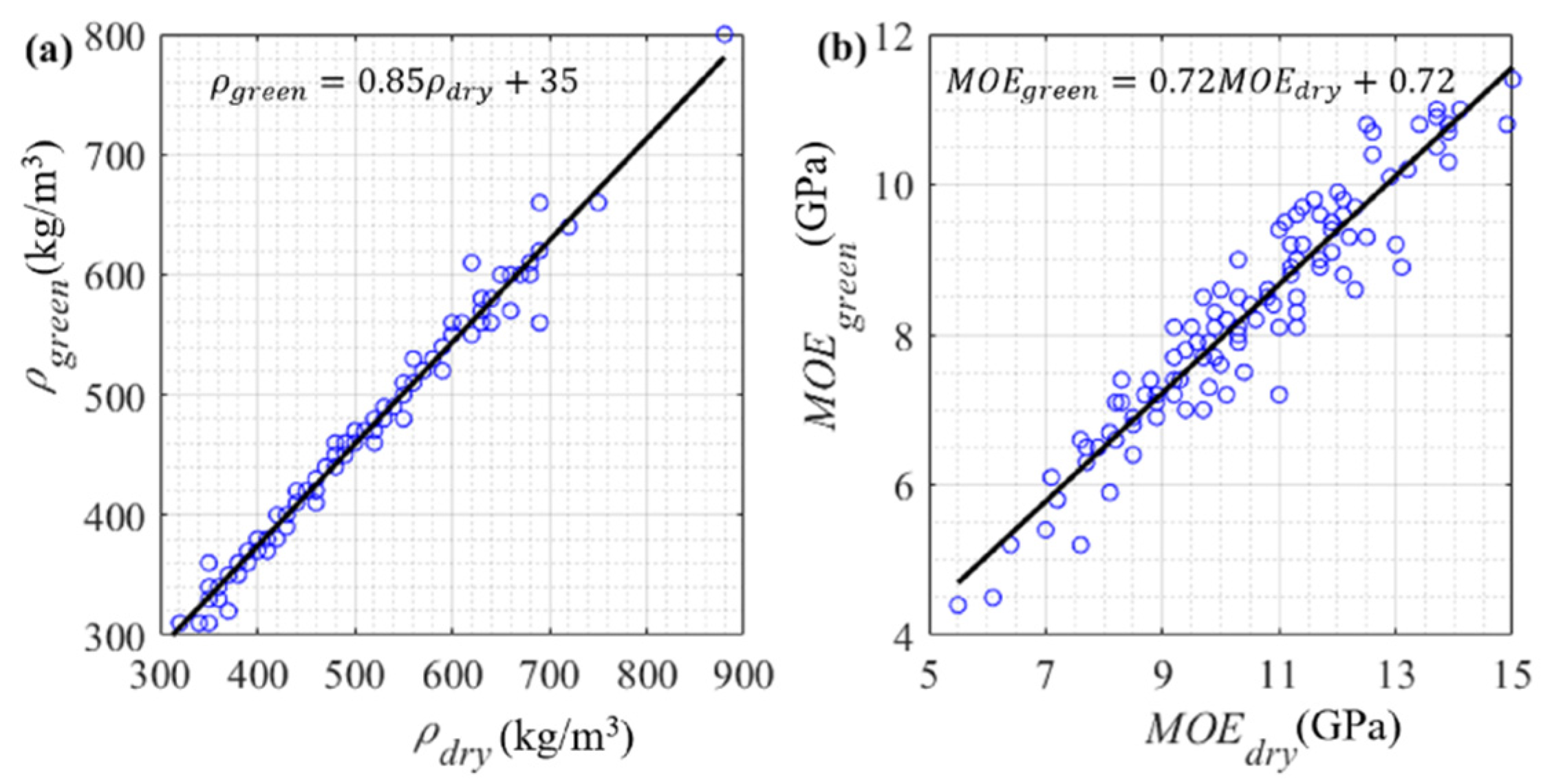
The ANSYS finite element software package (ANSYS, Inc., Canonsburg, PA, USA) was employed to calculate branch modes. Because the transverse dimensions of the trunk and the branches are far less than their longitudinal dimensions, they were modelled by three-dimensional beam elements based on Timoshenko’s beam theory [30]. The density and modulus of elasticity (MOE) of the trunk and the branches are 510 kg/m3 and 9 × 10⁹ Pa/m2, respectively [31], in which the coefficient of variation (COV) of MOE is 22% [32]. Because these are dry wood values, they need to be transferred into green wood values. Based on the Wood Handbook [32], the relationship of density and MOE between green wood and dry wood (12% moisture content) was established, as shown in Figure 3. Therefore, the density and MOE of green wood are 468 kg/m3 and 7.2 × 10⁹ Pa/m2, respectively.

2.5. Leaf Mass Estimation

Because the trunk frequency depends on the stiffness and mass of trunk and crown, the leaf mass can be estimated by comparison between the fundamental trunk frequency derived from SISO and that of the FEM, in which leaf mass can be adjusted to match the fundamental trunk frequency.

2.6. Identification of Branch Modes

Effective mass fraction was used to identify which branch modes contribute the most to the overall dynamic response. The frequencies corresponding to these branch modes are defined as crown frequencies. The calculation process is described as follows.
The generalized mass matrix, m ^ , is
m ^ = Φ T M Φ
where Φ is the eigenvector matrix, and M is the mass matrix.
The influence vector, r ¯ , represents the specified arbitrary displacements with initiating the free vibration of a system [33]. Defining the coefficient vector, L ¯ , as
L ¯ = Φ T M r ¯
the modal participation factor, Γ i , for mode i is
Γ i = L ¯ i m ^ i i
Then, the modal participating mass, Υ i , for mode i is obtained as
Υ i = m ^ i i Γ i 2
The effective mass fraction, Ψ i , for mode i is obtained as
Ψ i = m ^ i i Γ i 2 a = 1 N m ^ a a Γ a 2
where N is total number of modes.

3. Results

3.1. Prototype Characteristics

3.1.1. Geometry and Morphology

The geometric dimensions (including total height, trunk height, diameter at breast height (DBH), crown height and diameter) are illustrated in Table 1. The trunk has a height of 3 m and varying diameters along its height, ranging from 0.153 m to 0.185 m.
Ten main branches support the crown, and the branch numbers are shown in Table 2. Nos. 1–2 branches support the vertical crown, Nos. 3–8 branches support the lateral crown, and Nos. 9–10 branches integrate the crown. The Nos. 1–10 branches are pinpointed by the proximal diameters of branches connected to the main trunk, branch length, vertical angles and horizontal angles, as shown in Table 2.
The typical leaf cluster of the prototype is made up of five leaves, and each leaf consists of a lamina and a petiole. From qualitative observations of multiple leaf clusters, the averaged shape of the lamina resembles an ellipse, with long and short diameters of 4.4 cm and 9.1 cm, respectively, and the length of the petiole is 1.8 cm.

3.1.2. Leaf Mass Estimation

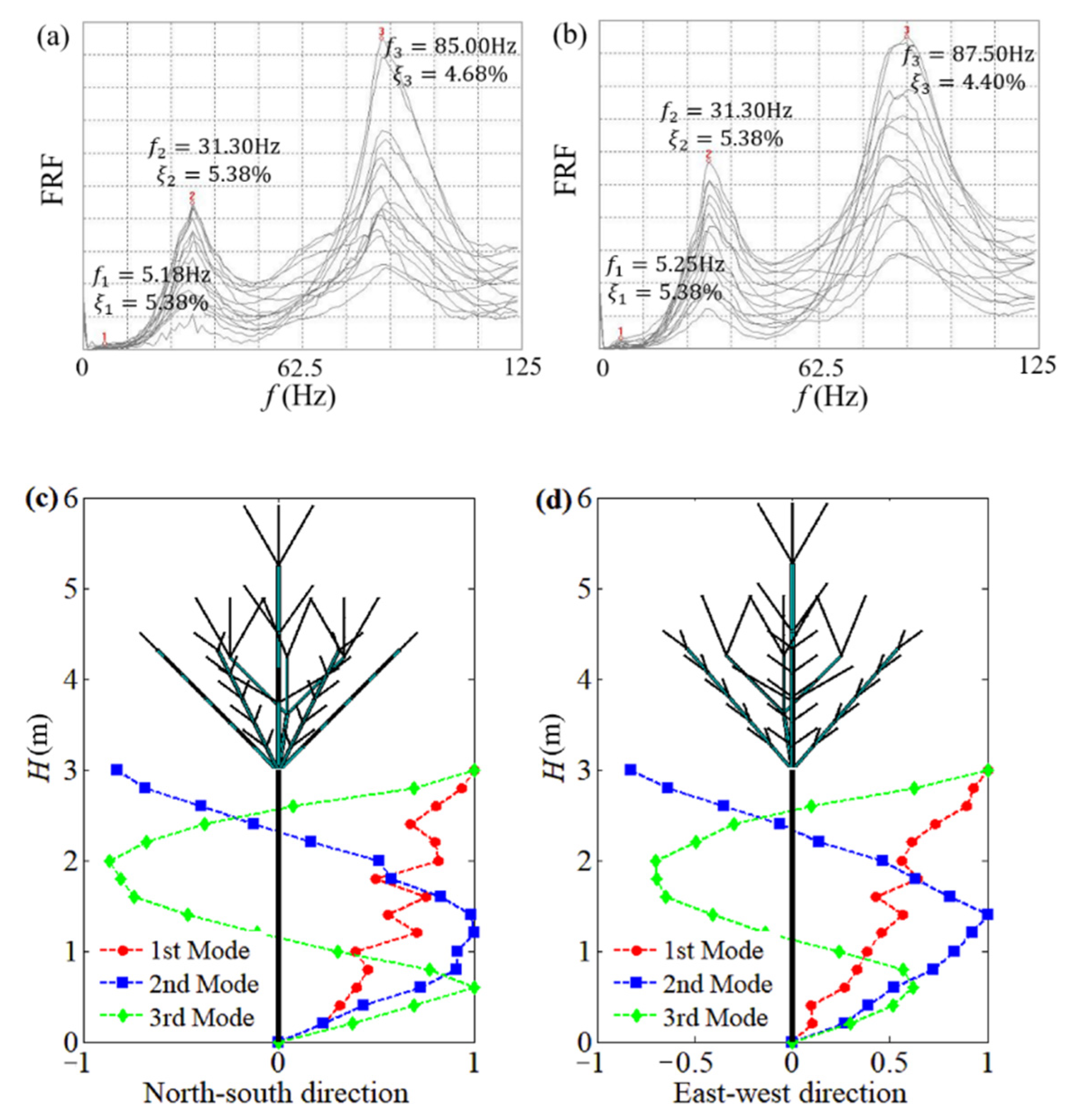
Based on leaf mass influence on trunk frequency, identifying trunk frequency is a prerequisite for leaf mass estimation. Figure 4a,b illustrates the frequency response functions (FRF) of the prototype in the north–south and east–west directions, and the mode shapes corresponding to the first three peaks of the FRFs are further identified, as shown in Figure 4c,d. Because the mode shapes present typical shape characteristics of a cantilever, the first three frequencies and damping are associated with the trunk. The first frequencies of the trunk in the orthogonal directions are 5.18 Hz and 5.25 Hz, while the corresponding damping for both is 5.38%, which verifies the symmetry of the prototype.
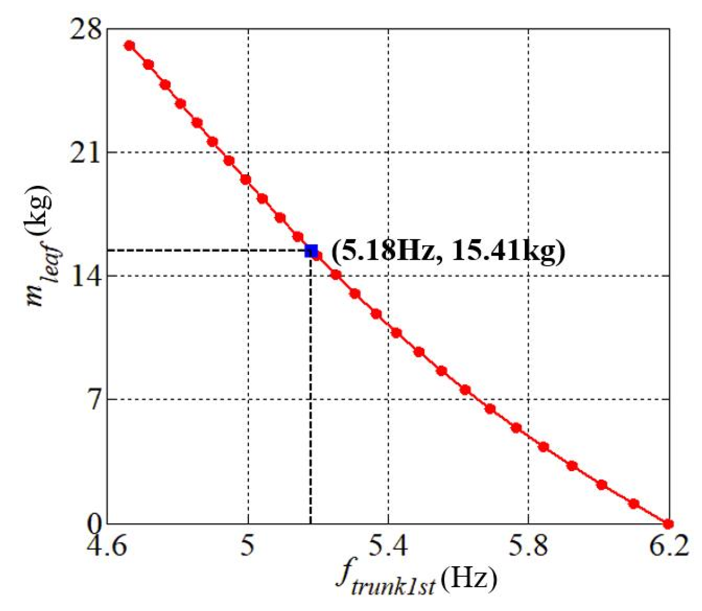
The FEMs of Nos. 1–10 branches were simplified according to branch dimensions, as shown in Table 2. Based on the geometric dimensions of the prototype (Table 1 and Table 2) and material properties, the FEM of the prototype was established. The leaf clusters were modelled as lumped masses attached uniformly to the branches of order 2 and 3 according to the visual observation. Figure 5 illustrates the relationship between fundamental trunk frequency and total leaf mass. The fundamental trunk frequencies decrease with increasing leaf mass. The uncertainty of the estimated leaf mass is based on the fact that the minimum change in leaf mass no longer affects the fundamental trunk frequency. When leaf mass is 15.41 kg, the fundamental trunk frequency of the FEM is consistent with that derived from SISO. Therefore, the estimated total leaf mass is 15.41 kg.
It is necessary to evaluate the effect of variations of MOE and mass on the effective mass fraction. According to Equation (1) to Equation (5), the effective mass fraction is determined by relative distributions of stiffness and mass of the system. To keep the same frequency, the total mass of the tree (including leaf, branches and trunk) varies linearly with MOE based on the frequency formula ( f = k / m , k MOE , where k is the stiffness and m is the mass). This indicates that the relative distributions of stiffness and mass keep constant. Based on that, the variations of MOE and mass have little effect on the effective mass fraction. On the other hand, each specific MOE requires a matched mass to keep the frequency constant. Therefore, the FEM of the prototype with the specific MOE (7.2 × 10⁹ Pa/m2) and the matched leaf mass (15.41 kg) can reflect the contributions of branch modes to the overall dynamic response.

3.1.3. Multimodal Dynamic Characteristics

The FEM of the prototype with correct leaf mass was used to identify the modes of the branches and the trunk. A total of 208 vibrational modes were calculated, where a branch mode is defined as the motion when a single or multiple branches sway independently without the trunk swaying (or with the trunk swaying slightly), while a trunk mode is defined as when the trunk sways significantly. Figure 6a illustrates the frequencies of the first twenty-four vibrational modes in orthogonal directions. The first twenty-two vibrational modes are associated with branches, while the 23rd and 24th vibrational modes are associated with the trunk. This indicates that the branch modes are characterized by a high modal density. To further identify these dense branch modes, Figure 6b presents the effective mass fraction of each mode. It can be seen that the vibrational modes with large effective mass fraction are the 1st, 2nd, 3rd, 4th, 23rd and 24th modes, which account for 13%, 14%, 9%, 10%, 17% and 18%, respectively. The cumulative effective mass fraction of the remaining branch modes accounts for less than 1%. This indicates that the contribution to dynamic response of the first four branch modes is far larger than that of other branch modes. Through checking the mode shape of each branch mode, it is found that branch modes with a small effective mass fraction have localized vibration of a few branches, while branch modes with a larger effective mass fraction are collaborative vibration of multiple branches. This indicates that the number of branches swaying in phase determines the magnitude of effective mass fraction of the branch mode.
The mode shape of branch mode one and two at 1.48 Hz are for all when all branches sway in phase (Figure 6c), while the mode shape of branch modes three and four at 1.83 Hz are when multiple branches sway in phase with a few branches swaying out of phase (Figure 6d). The mode shape of trunk modes 23 and 24 at 5.18 Hz are for when the trunk sways out of phase with the crown (Figure 6e). The cumulative effective mass fraction of the aforementioned six modes is 81%, which indicates that it is sufficient to reflect the dynamic response of the prototype for the aeroelastic model of the decurrent tree to match crown and trunk frequencies (i.e., 1.49–1.83 Hz, 5.18 Hz) of the prototype. The parameters of dynamic characteristics of the prototype are summarized in Table 3. Because the damping of the prototype at the crown frequencies is not identified, the damping of broad-leaved trees at fundamental frequencies is provided as a reference [34].

3.2. Characteristics of the Aeroelastic Model Tree

3.2.1. Scaled Models of Trees

Scaled models of trees are approximately divided into four types based on similarity level between the model and prototype. The first type is extremely simplified models that neglect the detailed crown morphology. Such trees are often modelled by aluminum rods, metal rings, and open-cell polyester foam [35,36,37,38,39,40]. The second type of model scales the crown morphology to some extent, but is relatively rigid compared to the prototypes. This type of models is made of, for example, brushes, metal screens, cotton balls, wooden pegs, plastic stripes or match sticks [41,42,43,44,45,46,47,48,49]. More recently, 3-D printed models have been built by matching specific LAD [50], or the aerodynamic similarity of the momentum absorption [4]. The third type is dwarf potted trees and branches resembling trees [51,52,53,54,55,56,57,58,59,60,61]. The fourth type is scaled, aeroelastic models that meet similarity criteria, in which Finnigan and Mulhearn’s wheat models [62] and Stacey’s excurrent tree models [12] are the representatives. The similarity level of geometry, crown morphology and dynamics between models and prototypes directly determines applicability of scale model testing results in full scale. By neglecting crown morphology, the first type is used to study aerodynamics related to forests more than for single trees. The relative rigidity of the second type may miss the effects due to tree dynamics [50], such as crown streamlining. The mismatches of the third type in the dimensions of the trunk, branches and leaves make it challenging to transfer from the measured results in wind tunnel tests to full-scale dimensions for high wind speed ranges [45]. Neglecting the ears and leaves of wheats in Finnigan and Mulhearn’s models could cause the mismatch on aerodynamics and flexural rigidity. Stacey’s models are somewhat simplified, neglect crown streamlining and have incorrect mass and bending stiffness distributions compared with full-scale prototypes. The mismatch in the mass causes a mismatch in the Froude number, which makes it challenging to apply wind tunnel results in full scale. Based on that, scaled, aeroelastic models of trees that satisfy the similarity criteria for wind tunnel tests could effectively overcome the existing deficiencies and improve the applicability of tree models.

3.2.2. Model Designs

The structural design of the aeroelastic model of the decurrent tree (including trunk and branches) described by Hao et al. [5] is briefly reviewed in this section.
Based on the requirements of the similarity parameters (including length, drag coefficients, mass, bending stiffness and the size of wind tunnel), a 1:6 geometrically scaled model of the tree is selected for wind tunnel tests. The trunk model is designed as the combination of a central spine and cladding modules. A high-strength aluminum rod ( ρ = 2700   kg / m 3 , E = 6.91 × 10 10   Pa / m 2 ) of a circular cross section serves as the “spine” of the trunk model. Based on the diameters at 15 trunk heights and elastic modulus of the trunk, the aluminum spine was machined according to the bending stiffness scale. The aerodynamic shape of the trunk was completed by 15 cladding segments affixed to the spine. In order to prevent the additional stiffness from the cladding segments, gaps of 0.8 mm are imposed between two adjacent cladding segments. By altering the wall thickness of the cladding segments, the modelled mass of the trunk was adjusted to match the mass scale. The properly scaled mass and bending stiffness ensures that the trunk model matches the trunk frequency of the prototype.
The requirements for the branch models are similar to these for the trunk model. However, the design for the trunk is not suitable for the branches because of small diameters of branch models at the length scale. Therefore, a combination of aluminum wire ( ρ = 2700   kg / m 3 , E = 6.91 × 10 10   Pa / m 2 ) and rigid hollow rods ( ρ = 930   kg / m 3 ) based on equivalent displacement was used as an alternative. Because the aeroelastic model and the alternative model have the same displacement under the same load, it ensures the consistency of branch streamlining and bending stiffness. The final branch mass specified by the mass scale is obtained by adjusting the wall thickness of the rigid hollow rods. The aerodynamic shape of the branches was completed by altering the diameters of the rigid hollow rods according to length scale. A total of 10 order-1 branches and 102 order-2 branches was made to model the crown frame of the prototype.
Leaf effects on tree are reflected on dynamic characteristics of tree and crown morphology and, hence, the total leaf mass and leaf area index (LAI) were employed as key parameters for leaf cluster models. The leaf cluster model was made up of steel piano wire and plastic sheet according to the typical leaf cluster of the prototype. The model neglected the dynamic characteristics of the leaf cluster, but scaled the aerodynamic shape of the single-leaf cluster of the prototype. The excess stiffness reduces the streamlining of the modelled cluster that should be observed in the prototype in strong winds.

3.2.3. Model Configurations

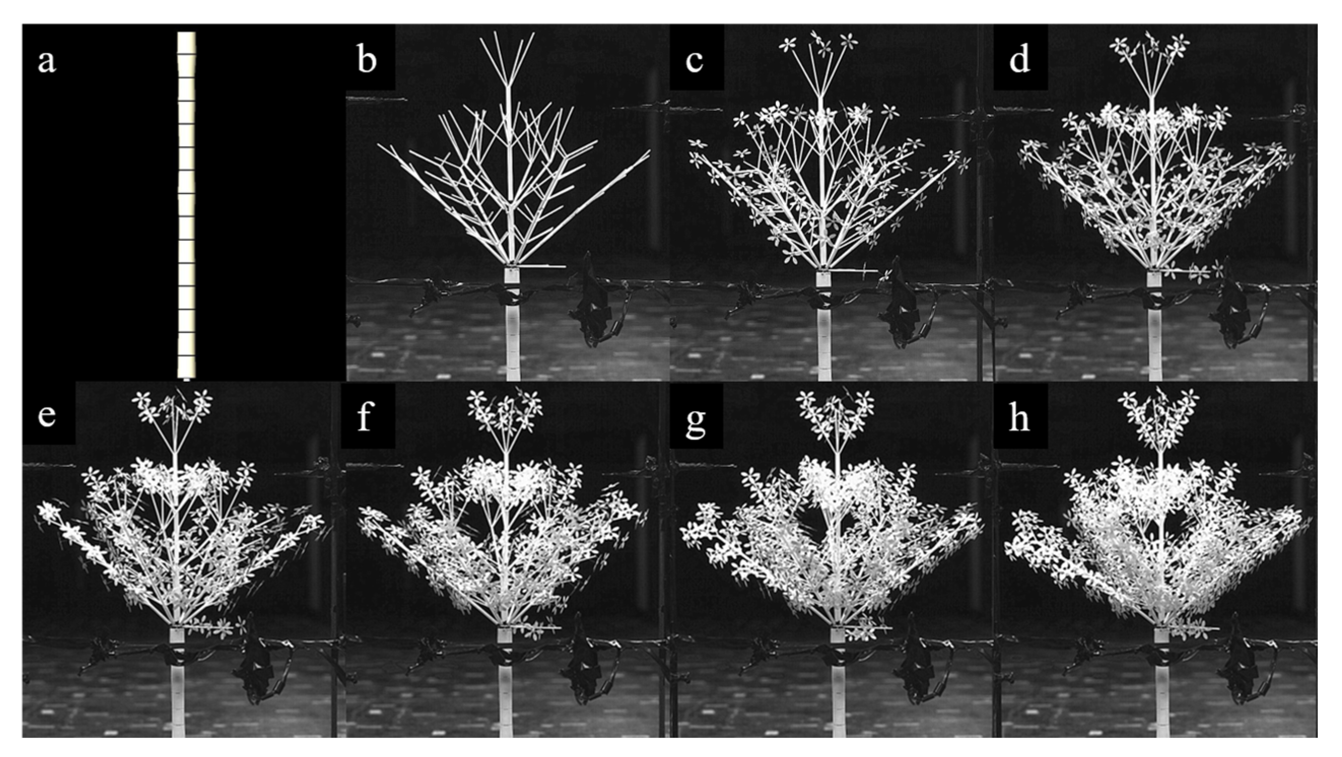
Based on the total leaf mass of the prototype (Table 3) and the LAI of typical camphor trees (1.99–3.27) [63], there are 540 leaf cluster models made with total mass 0.1069 kg and total area 0.2522 m2. In order to achieve the similarity of leaf mass and LAI, leaf cluster models were incrementally added to the crown frame to form eight distinct crown configurations, as shown in Figure 7. The case C1, shown in Figure 7a, is the bare trunk configuration The case C2, shown in Figure 7b, adds the branches on top of the trunk. Starting from the case C3, increasing the case number by one means that one more leaf cluster is added to the original tree configuration, from the ends of the order-2 or -3 branches. It is worth noting that the leaf cluster models neglect the dynamic characteristics of the leaf cluster of the prototype, but scaled the aerodynamic shape of the single-leaf cluster of the prototype. The excess stiffness reduces the streamlining of the modelled cluster that should be observed in the prototype in strong winds.

3.2.4. Crown Vertical Distributions

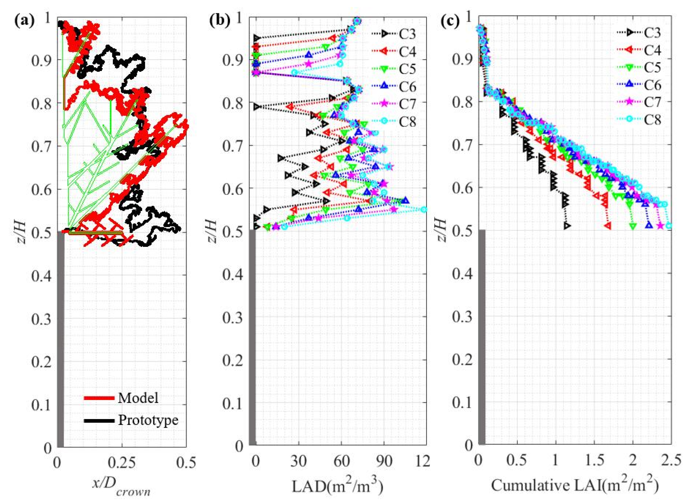
Crown profile, leaf area density (LAD) and LAI were used to represent the vertical foliage structure, where LAD is defined as the total one-sided leaf area per unit layer volume, and LAI is defined as the leaf area per unit ground area [64].
The crown profile of the model for case C8 is compared to the prototype in Figure 8a. The crown profile of the model is close to that of the prototype except for the top and bottom.
Figure 8b illustrates LAD profiles of the model along the crown height for cases C3 to C8. For case C3, the least numbers of leaf clusters determine the sparsest LAD, while for case C8, determines the densest LAD. The average LAD was used to assess the average leaf area per unit crown volume. The average LAD for case C3 is 5.00 m2/m3 at full scale, which is close to that of a typical camphor tree (5.40 m2/m3) [65], while the average LAD for cases C4 to C8 is larger than that of a typical camphor tree.
Figure 8c illustrates cumulative LAI profiles of the model along the crown height for cases C3 to C8. The cumulative LAI of the model for cases C3 to C8 at the crown bottom is 1.14, 1.68, 2.00, 2.21, 2.35 and 2.46, respectively. The model for cases C5 to C8 overlaps the cumulative LAI of typical camphor tree (1.99–3.27) [63].

3.3. Characteristics of the Aeroelastic Model Tree

To assess the fidelity of the aeroelastic model in the wind tunnel, the aerodynamic effects, which are mainly controlled by the crown morphology, and the dynamic characteristic of the model, will be examined in detail in this section.

3.3.1. Crown Morphology

The main geometry dimensions of the aeroelastic model match these of the prototype according to the target length scale 1:6, as shown in Table 1.
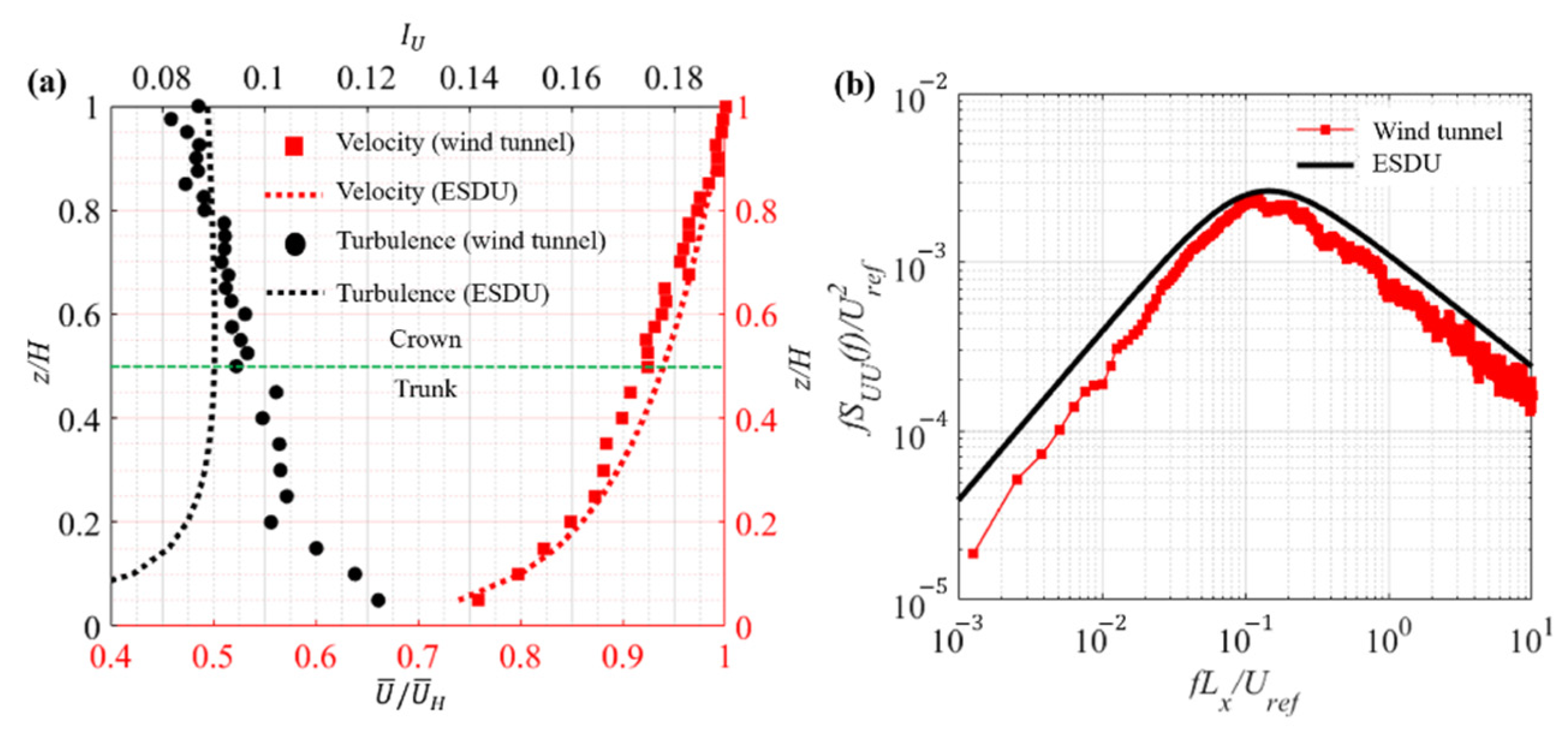
The drag coefficient ( C f = 2 F D ρ A U U 2 , where F D is the drag, ρ is the air density, A U is the frontal area and U is the wind speed) of the aeroelastic model was measured in the Boundary Layer Wind Tunnel II (BLWT II) at Western University, Canada. Because the upstream terrain of the prototype is close to flat, the simulation of the turbulent atmospheric boundary layer (ABL) flow was determined by comparing the full-scale wind speed profile given by ESDU 85020 [66] (2008). Vertical profiles of the mean velocity and turbulence intensity of the aforementioned ABL flows are shown in Figure 9a. The mean velocity profile of the wind tunnel terrain is similar to that of full-scale terrain along the tree height. Because the ratio between the crown area and trunk area is 2.82–9.12, the aerodynamic force of the model is mainly caused by crown. The similarity of the turbulence intensity profiles at the crown height between the wind tunnel terrain and the full-scale terrain meets the requirement of the wind tunnel test, except below the crown, close to ground, where the turbulence intensities are too high. The power spectral density (PSD) functions of streamwise velocities at reference height (z = 0.85 H) for the ABL flow in the wind tunnel terrain is similar to that for the theoretical full-scale ABL flow, as shown in Figure 9b. It is worth noting that the dimensionless integral length scale ( L x / D c r o w n , where L x is integral length scale, and D c r o w n is the crown diameter projected to the ground) of the wind tunnel terrain (1.68) is significantly smaller than that of the full-scale ABL flow (26.86), which is caused by the primary issue when using relatively larger scale models in typical boundary layer wind tunnels. This mismatch will lead to a crown response that is underestimated. However, because the large-scale gusts are in the quasi-steady range, the effect is similar to there being a slightly lower mean wind speed. In other words, while the displacements of the crown are accurate for the particular gust speeds in the wind tunnel simulation, larger gust speeds and deflections would be observed in the true terrain. In contrast, the higher turbulence levels acting on the trunk, close to the ground, may lead to small changes in the trunk response given the relatively small turbulence levels (between 10–12%).
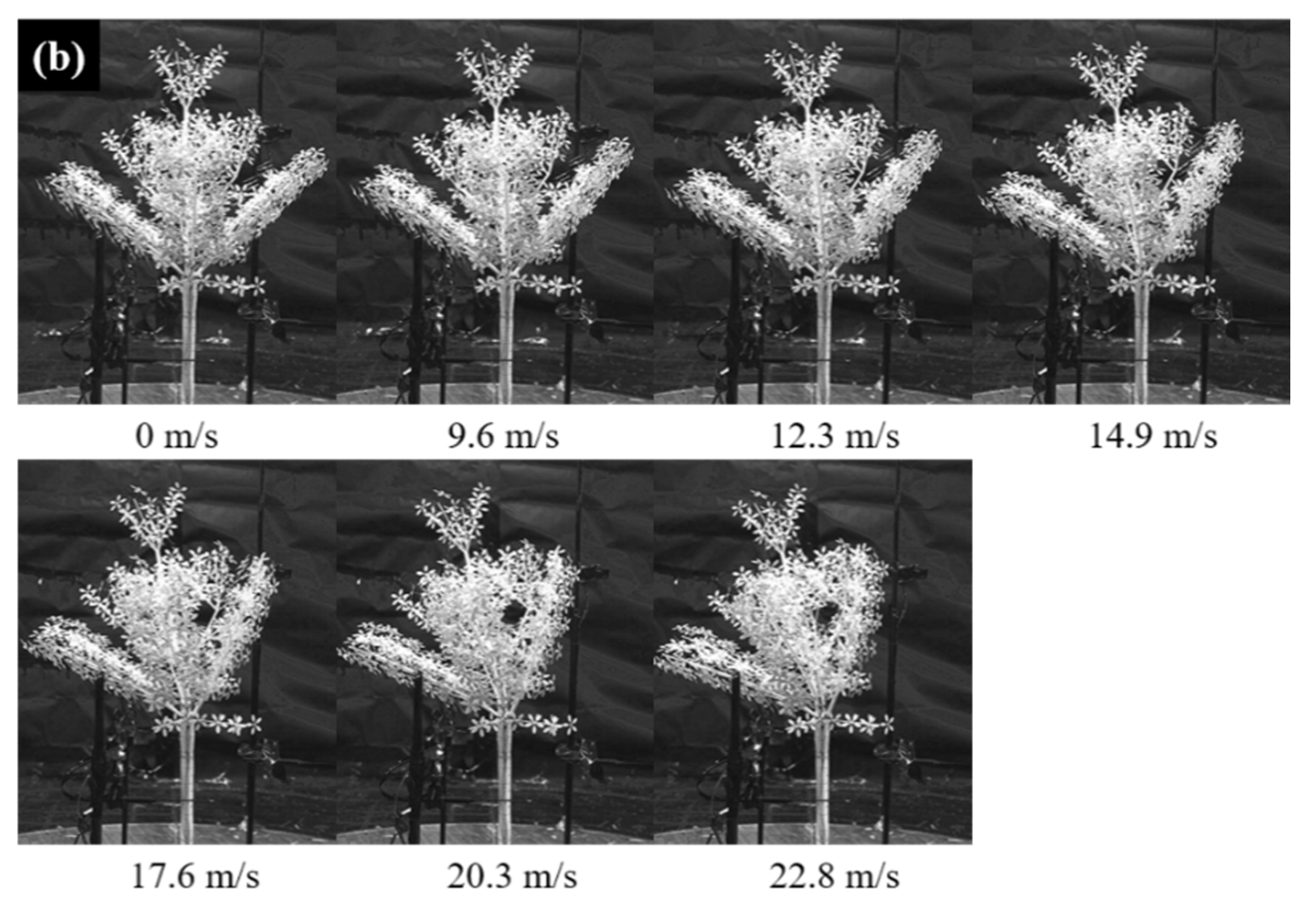
Figure 10a depicts relationships between drag coefficients and wind speed of the model for cases C1 to C8, in which the wind speed was converted into full scale according to velocity scale 1:2.45 [5], and other typical broad-leaved trees, including rose of Sharon [67], poplar trees [25], black cottonwood, trembling aspen, red alder, paper birch and bigleaf maple [68]. The drag coefficients for case C1 are 0.22 to 0.18 at wind speeds of 3.9 m/s to 9.3 m/s, while for case C2, the drag coefficients dramatically increase to 0.40–0.36 at the same wind speeds, which indicates that the crown frame greatly changes the aerodynamic shape of the model. The drag coefficients increase rapidly with increased numbers of leaf clusters (for cases C3 to C4) and tend to be steady when there are relatively more leaf clusters (for cases C5 to C8). The former is mainly caused by the initial increased number of leaves significantly changing the aerodynamic shape of the model, while the latter indicates that the aerodynamic shape of the model changes more slowly with more leaves. The variation of drag coefficients generally overlap those reported for the typical broad-leaved trees.
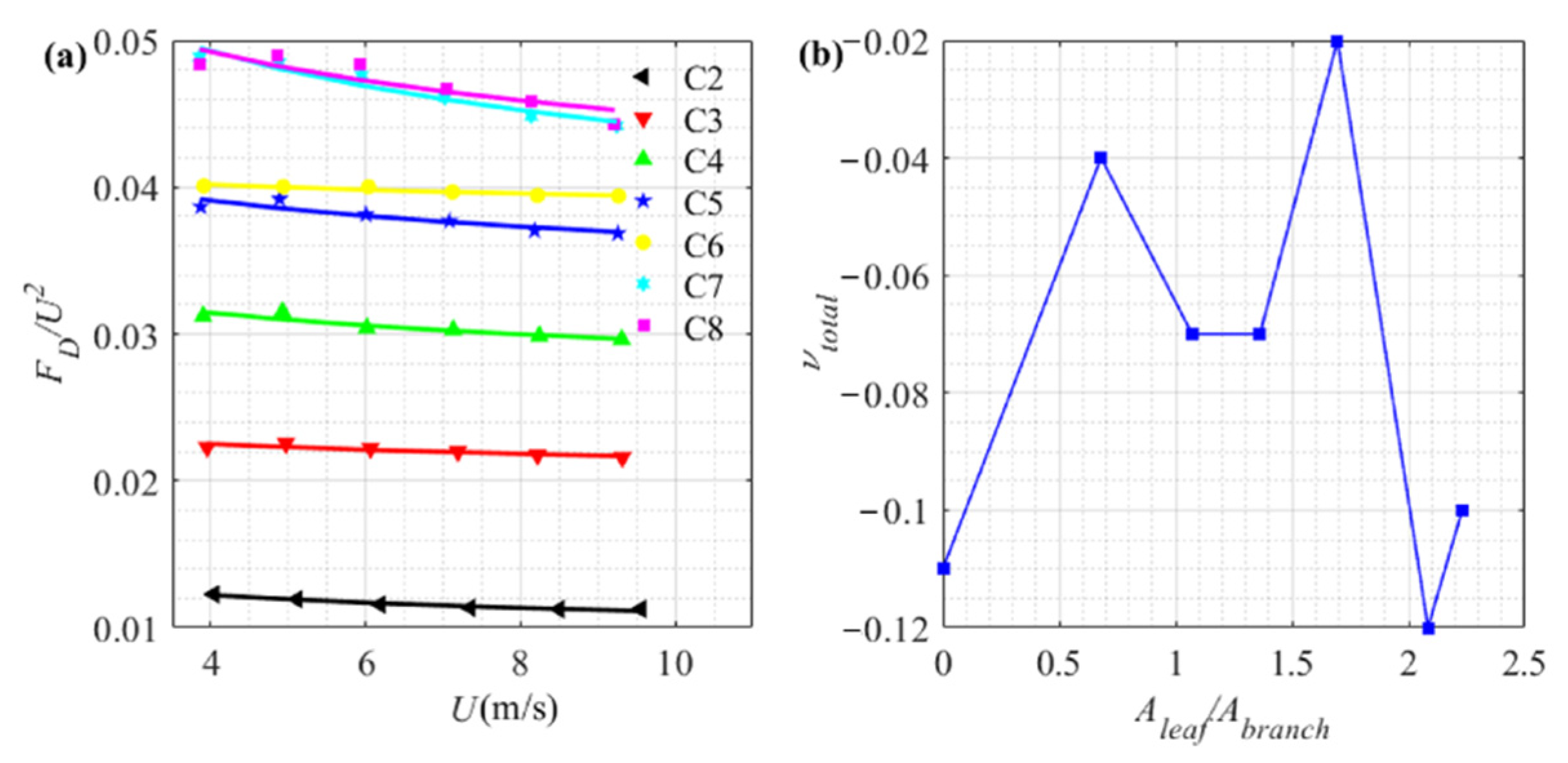
It is worth noting that the drag coefficients of the model decrease with increased wind speed, but this declining rate of the model is slower than that of the real trees (Figure 10a). The declining trend of the drag coefficients is mainly caused by streamlining effects [28]. Although the current aeroelastic model enables the streamlining behaviour observed in the crown, as shown in Figure 10b, the leaf clusters are suspected to have excess rigidity, as pointed out by Hao et al. [5], which leads to slower declination of the measured C f .
In this analysis, the contributions of branch and leaf to the total observed streamlining effects are further quantified, using the Vogel exponent [28], i.e.,
F D / U 2 U ν t o t a l
ν t o t a l = ν b r a n c h + ν l e a f
where ν t o t a l is the total Vogel exponent, ν b r a n c h is the Vogel exponent associated with the branch streamlining effects, and ν l e a f is the Vogel exponent associated with the leaf streamlining effects.
Figure 11a depicts relationships between speed specific drag ( F D / U 2 ) versus wind speed (U) of the model for cases C2 to C8. F D / U 2 decreases with increased wind speed, which indicates that Vogel exponents for cases C2 to C8 are negative. Subplot (b) in Figure 11 further depicts relationship between total Vogel exponent ( ν t o t a l ) versus ratio of frontal area between leaf and branch ( A l e a f / A b r a n c h ). When A l e a f / A b r a n c h = 0 , ν b r a n c h is equal to ν t o t a l . When A l e a f / A b r a n c h > 0 , ν l e a f is obtained by subtracting ν b r a n c h from ν t o t a l . The ν b r a n c h of the model is −0.11, which is close to that of real broad-leaved trees, including poplar (−0.11), maple (−0.13) and oak (−0.08), as shown in Table 4. This indicates that the model replicates the branch streamlining effects of the broad-leaved trees. While the ν l e a f for cases C3 to C8 are 0.08, 0.05, 0.05, 0.10, −0.01 and 0.01, respectively, which are of the opposite sign and 1/10 smaller in magnitude than the crown exponents. As compared to the real broad-leaved trees shown in Table 4, which includes poplar (−0.60), maple (−0.64) and oak (−0.72), the obvious excess rigidity of the model leaf clusters can again be observed. Furthermore, the contribution of the branch accounts for more than 10% of the crown streamlining effects for the broad-leaved trees shown in Table 4. Although the branch streamlining effects accounts for less than 20% of the crown streamlining effects, it determines crown deflection in along-wind direction.
Table 4. Vogel exponents of poplar, maple and oak.
Specie ν t o t a l ν l e a f ν b r a n c h
Poplar−0.71 [69]−0.60 [28]−0.11
Maple−0.77 [24]−0.64 [28]−0.13
Oak−0.80 [24]−0.72 [28]−0.08

3.3.2. Mass and Bending Stiffness Distributions (Frequency)

The frequencies of the model for cases C1 to C8 were identified by free vibration decay tests of the trunk. The crown was pushed and released from a large elastic displacement. Then, the time history of the free vibration measured on the top of the trunk was recorded using an accelerometer. The natural frequencies were identified by the locations of peaks of the PSD functions of time history of the free vibration curve. Figure 12 illustrates frequencies of the model in the along-wind and across-wind directions. The ranges of the crown and trunk frequencies are 2.79–4.85 Hz and 11.78–15.90 Hz, respectively. The crown and trunk frequency ratios between the model and the prototype are 1.87:1–3.26:1 and 2.27:1–3.07:1, respectively, which covers the target reduced frequency ratio of 2.45:1. This validates similarity of mass and bending stiffness distributions between the model and the prototype. Likewise, the ratio of the first two frequencies of the model (1:3 to 1:4), that is close to an olive (decurrent) tree (1:2) [70] and a Scots (excurrent) tree (1:3) [71], validates the model structure.

3.3.3. Damping

The same method for identifying the frequency of the model was used to identify the damping of the model. The free vibration decay time history atop the trunk was recorded by two displacement transducers oriented in the streamwise and across-wind directions. The logarithmic decrement formula is used to calculate damping, i.e.,
δ = ln D i D i + 1 = 2 π ξ 1 ξ 2
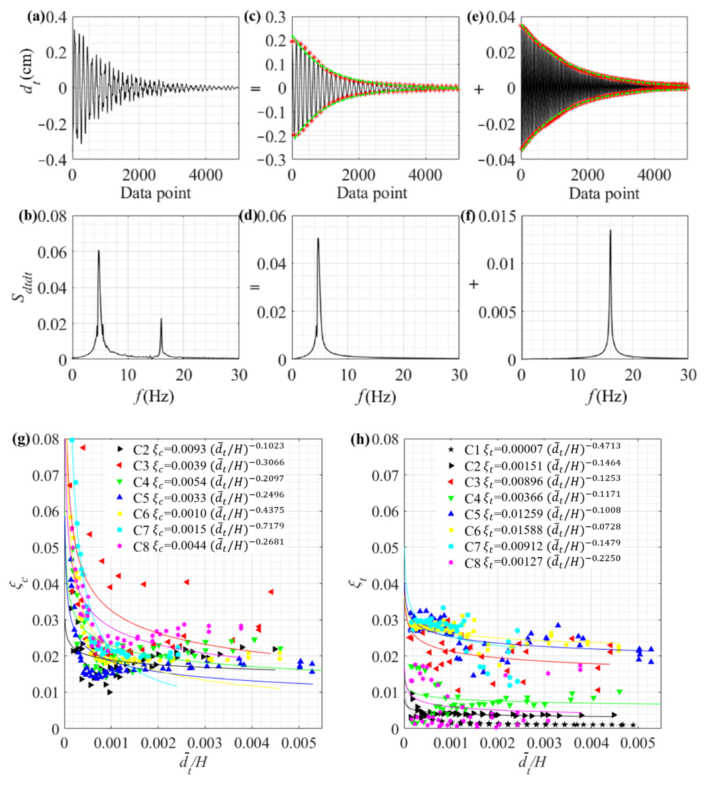
where δ is logarithmic decrement, D i and D i + 1 are two successive peaks of amplitude, and ξ is damping. The decaying free vibration time history shown in Figure 13a was measured on top of the trunk, which includes the crown and the trunk frequency components, as can be seen in the PSD function shown in Figure 13b. To obtain the decaying free vibration of the crown, the spectral energy associated with the crown is first isolated, as shown in Figure 13d, and used to reconstruct the time history (Figure 13c) by the inverse Fourier transform. The damping associated with the trunk was identified in the same manner, and the associated decaying displacement and spectral energy are shown in Figure 13e,f, respectively. The damping associated with the trunk and the crown frequencies are obtained by fitting the peaks with envelope curves using Equation (8).
This process was repeated for different initial trunk displacements, d ¯ t , to see the effects on damping. The results for crown and trunk are shown in Figure 13g,h, respectively. As can be seen, the damping is generally higher when the initial displacement is small. As the imposed displacement becomes larger but less than   d ¯ t / H 0.1 % , the identified damping decreases. Further increasing the initial displacement (i.e.,   d ¯ t / H > 0.1 % ) does not alter the damping significantly. As compared to the crown damping shown in Figure 13g, the trunk damping in Figure 13h diverges more, possibly due to the direct connection to the ground, which is more sensitive to the details of the connection. The maximum crown damping is about 8.5% observed in C7, which is close to the reference (6–8%) [34]; The maximum trunk damping is about 3.3% observed in C7, which is smaller than the target trunk damping of the prototype (5.4%). This gap about the trunk damping between the model and the prototype would cause discrepancy on swaying behaviour of the trunk under wind load.
The parameters of dynamic characteristics of the model at full scale are summarized in Table 3. In summary, the aeroelastic model properly simulates the aerodynamic shape, branch streamlining effects, crown damping, mass and bending stiffness distributions of the prototype. However, because of excess bending stiffness of the leaf cluster models, the aeroelastic model has incorrect leaf streamlining effects and trunk damping compared with the prototype.

4. Discussion

4.1. Multimodal Dynamics of Decurrent Trees

The leaf effects on trees are reflected in the dynamic characteristics of the tree and crown morphology. For the aeroelastic model of the decurrent tree, leaf clusters cause the drag coefficients to increase from 0.40 to 0.63 (Figure 10a) and the frontal area to increase from 0.0516 m2 to 0.1366 m2 [5], indicating that wind loading of the model with leaf clusters is a factor of 4.2 larger than that of the model without leaves under the same wind conditions. The same leaf clusters cause the crown frequency at full scale to decrease from 1.98 Hz to 1.14 Hz (Figure 12). Although this slight variation of crown frequency has limited effect on tree dynamics [10], the crown morphology changed by leaves dramatically increases wind loading of trees. Therefore, effectively estimating leaf mass is a key for constructing crown morphology of a scaled, aeroelastic model tree. The method of estimating leaf mass based on FEM without destruction solves this challenging issue. Because the principle of the method bases on the effect of crown mass on fundamental trunk frequency, total crown mass is determined by trunk frequency, which means that the mass of simplified branches determines the accuracy of estimated leaf mass. In this study, the curved branches were reduced into straight branches, and the branches with variable cross section were reduced into the branches with uniform cross section, which reduces the reliability of leaf mass. For improving reliability of the method, an effective way is to replicate curved branches with variable cross section of the prototype in detail as much as possible in FEM.
The high modal density associated with branches can vary and depends on tree architecture [3], especially the gap of slenderness ratio between the branches and trunk. For decurrent trees with shorter trunks, branch modes are likely to display lower frequencies relative to trunk modes, while for excurrent trees with longer trunks, branch modes could have frequencies close to, and even rank in between, trunk modes. This difference in tree architecture may lead to different failure forms in which branch failure is earlier than trunk failure for decurrent trees, while the opposite would be true for excurrent trees.

4.2. Challenges of the Aeroelastic Model

Although the scaled, aeroelastic model of the decurrent tree properly replicates the aerodynamic shape, branch streamlining, and has correct distributions of mass and bending stiffness, there are still some limitations for the aeroelastic model of the decurrent tree. One of main challenges is the excess stiffness of the leaf cluster model, which has a non-negligible effect on the aeroelastic model tree. These limitations mainly reflect on: (i) leaf streamlining effects and (ii) damping. The former overestimates wind load of the model under the same wind conditions, while the latter is mainly caused by strengthened leaf collisions, which leads to a mismatch of wind-induced dynamic behaviour between the model and the prototype.
There are two theoretical approaches to solve the issue of mismatch of leaf stiffness between the model and prototype. The first approach is to simulate each leaf stiffness of the prototype directly. However, this is unrealistic because leaves on the prototype are numerous and their stiffness varies. A more applied approach is to match the Vogel number such that the overall streamlining effects are similar in the model and the prototype. To match the Vogel number in the scaled model, more detailed design of leaf cluster thickness can be done according to required leaf deformation.

5. Conclusions

In this study, the fundamental frequencies of the prototype were first measured using SISO, and an appropriate mass distribution was derived using a finite element model. An approach to establish leaf mass using FEM was developed. The effective estimation of leaf mass provides a reference for designing leaf cluster models. Effective mass fraction was used to distinguish branch modes. It was found that the number of branches swaying in phase determines the magnitude of effective mass fraction of branch modes. The first two branch modes, which contribute the most to the dynamic response of the decurrent tree, are all branches and most of the branches swaying in phase, respectively. The frequencies corresponding to these branch modes provide a reference for the aeroelastic model tree.
Challenges about the aeroelastic model of the decurrent tree remain, particularly the excessive stiffness in the leaf clusters. The Vogel exponent associated with leaf streamlining provides a dimensionless parameter associated with leaf deformation, which may help establish the consistency of leaf stiffness between the model and prototype.

Author Contributions

Conceptualization, Y.H.; methodology, Y.H.; software, Y.H. and C.-H.W.; validation, Y.H. and C.-H.W.; formal analysis, Y.H.; investigation, Y.H.; resources, Z.L. and G.A.K.; data curation, Y.H.; writing—original draft preparation, Y.H.; writing—review and editing, Z.L., G.A.K. and C.-H.W.; visualization, Z.L.; supervision, Z.L. and G.A.K.; project administration, Z.L.; funding acquisition, Z.L. and G.A.K. All authors have read and agreed to the published version of the manuscript.

Funding

This research was funded by the National Natural Science Foundation of China under contract No. 51678233, the Natural Sciences and Engineering Research Council (NSERC) of Canada under the Discovery Grants program, and the China Scholarship Council (CSC).

Institutional Review Board Statement

Not applicable.

Informed Consent Statement

Not applicable.

Data Availability Statement

Data that support the findings of this study are available from the corresponding author upon reasonable request.

Acknowledgments

G.A.K. gratefully acknowledges support from ImpactWX and Western University for support through his Chair in Severe Storms Engineering.

Conflicts of Interest

The authors declare no conflict of interest.

References

  1. Sills, D.M.L.; Kopp, G.A.; Elliott, L.; Jaffe, A.; Sutherland, E.; Miller, C.; Kunkel, J.; Hong, E.; Stevenson, S.; Wang, W. The Northern Tornadoes Project—Uncovering Canada’s true tornado climatology. Bull. Am. Meteorol. Soc. 2020, 101, 2113–2132. [Google Scholar] [CrossRef]
  2. Mansour, M.A.; Rhee, D.M.; Newson, T.; Petersen, C.; Lombardo, F.T. Estimating wind damage in forested areas due to tornadoes. Forests 2021, 12, 17. [Google Scholar] [CrossRef]
  3. Gardiner, B.; Berry, P.; Moulia, B. Review: Wind impacts on plant growth, mechanics and damage. Plant Sci. 2016, 245, 94–118. [Google Scholar] [CrossRef] [PubMed]
  4. Gromke, C. Wind tunnel model of the forest and its Reynolds number sensitivity. J. Wind Eng. Ind. Aerodyn. 2018, 175, 53–64. [Google Scholar] [CrossRef]
  5. Hao, Y.F.; Kopp, G.A.; Wu, C.; Gillmeier, S. A wind tunnel study of the aerodynamic characteristics of a scaled, aeroelastic, model tree. J. Wind Eng. Ind. Aerodyn. 2020, 197, 104088. [Google Scholar] [CrossRef]
  6. Rodriguez, M.; Ploquin, S.; Moulia, B.; Langre, E.D. The multimodal dynamics of a walnut tree: Experiments and models. J. Appl. Mech.-Trans. ASME 2012, 79, 044505. [Google Scholar] [CrossRef]
  7. Spatz, H.; Theckes, B. Oscillation damping in trees. Plant Sci. 2013, 207, 66–71. [Google Scholar] [CrossRef]
  8. Langre, E.D. Effects of wind on plants. Annu. Rev. Fluid Mech. 2008, 40, 141–168. [Google Scholar] [CrossRef] [Green Version]
  9. James, K.R.; Haritos, N.; Ades, P.K. Mechanical stability of trees under dynamic loads. Am. J. Bot. 2006, 93, 1522–1530. [Google Scholar] [CrossRef]
  10. James, K.R.; Dahle, G.A.; Grabosky, J.; Kane, B.; Detter, A. Tree biomechanics literature review: Dynamics. Arboric. Urban For. 2014, 40, 1–15. [Google Scholar] [CrossRef]
  11. Spatz, H.; Bruchert, F.; Pfisterer, J. Multiple resonance damping or how do trees escape dangerously large oscillation? Am. J. Bot. 2007, 94, 1603–1611. [Google Scholar] [CrossRef]
  12. Stacey, G.R.; Belcher, R.E.; Wood, C.J.; Gardiner, B.A. Wind flows and forces in a model spruce forest. Bound-Layer Meteorol. 1994, 69, 311–334. [Google Scholar] [CrossRef]
  13. Rodriguez, M.; Langre, E.D.; Moulia, B. A scaling law for the effects of architecture and allometry on tree vibration modes suggests a biological tuning to modal compartmentalization. Am. J. Bot. 2008, 95, 1523–1537. [Google Scholar] [CrossRef] [PubMed]
  14. Ciftci, C.; Brena, S.F.; Kane, B.; Arwade, S.R. The effect of crown architecture on dynamic amplification factor of an open-grown sugar maple (Acer saccharum L.). Trees 2013, 27, 1175–1189. [Google Scholar] [CrossRef]
  15. Sellier, D.; Brunet, Y.; Fourcaud, T. A numerical model of tree aerodynamic response to a turbulent airflow. Forestry 2008, 81, 279–297. [Google Scholar] [CrossRef] [Green Version]
  16. Bentaher, H.; Haddar, M.; Fakhfakh, T.; Maalej, A. Finite elements modelling of olive tree mechanical harvesting using different shakers. Trees 2013, 27, 1537–1545. [Google Scholar] [CrossRef]
  17. Sellier, D.; Fourcaud, T.; Patrick, L. A finite element model for investigating effects of aerial architecture on tree oscillations. Tree Physiol. 2006, 26, 799–806. [Google Scholar] [CrossRef] [Green Version]
  18. Moore, J.R.; Maguire, D.A. Simulating the dynamic behavior of Douglas-fir trees under applied loads by the finite element method. Tree Physiol. 2008, 28, 75–83. [Google Scholar] [CrossRef]
  19. Sellier, D.; Fourcaud, T. Crown structure and wood properties: Influence on tree sway and response to high wind. Am. J. Bot. 2009, 96, 885–896. [Google Scholar] [CrossRef]
  20. Ciftci, C.; Arwade, S.R.; Kane, B.; Brena, S.F. Analysis of the probability of failure for open-grown trees during wind storms. Probabilistic Eng. Eng. Mech. 2014, 37, 41–50. [Google Scholar] [CrossRef]
  21. Peng, Y.; Wang, Z.; Ai, X. Wind-induced fragility assessment of urban trees with structural uncertainties. Wind Struct. 2018, 26, 45–56. [Google Scholar] [CrossRef]
  22. Manickathan, L.; Defraeye, T.; Allegrini, J.; Derome, D.; Carmeliet, J. Comparative study of flow field and drag coefficient of model and small natural trees in a wind tunnel. Urban For. Urban Green 2018, 35, 230–239. [Google Scholar] [CrossRef]
  23. Kane, B.; Smiley, E.T. Drag coefficients and crown area estimation of red maple. Can. J. For. Res. 2006, 36, 1951–1958. [Google Scholar] [CrossRef]
  24. Kane, B.; Pavlis, M.; Harris, J.R.; Seiler, J.R. Crown reconfiguration and trunk stress in deciduous trees. Can. J. For. Res. 2008, 38, 1275–1289. [Google Scholar] [CrossRef]
  25. Koizumi, A.; Motoyama, J.; Sawata, K.; Sasaki, Y.; Hirai, T. Evaluation of drag coefficients of poplar-tree crowns by a field test method. J. Wood Sci. 2010, 56, 189–193. [Google Scholar] [CrossRef]
  26. Koizumi, A.; Shimizu, M.; Sasaki, Y.; Hirai, T. In situ drag coefficient measurements for rooftop trees. J. Wood Sci. 2016, 62, 363–369. [Google Scholar] [CrossRef] [Green Version]
  27. Kitagawa, K.; Iwama, S.; Fukui, S.; Sunaoka, Y.; Yazawa, H.; Usami, A.; Naramoto, M.; Uchida, T.; Saito, S.; Mizunaga, H. Effects of components of the leaf area distribution on drag relations for Cryptomeria japonica and Chamaecyparis obtuse. Eur. J. Forest. Res. 2015, 134, 403–414. [Google Scholar] [CrossRef]
  28. Vogel, S. Drag and reconfiguration of broad leaves in high winds. J. Exp. Bot. 1989, 40, 941–948. [Google Scholar] [CrossRef]
  29. Reynders, E.; Degrauwe, D.; Roeck, G.D.; Magalhaes, F.; Caetano, E. Combined experimental-operational modal testing of footbridges. J. Eng. Mech. 2010, 136, 687–696. [Google Scholar] [CrossRef]
  30. Cowper, G.R. The shear coefficient in Timoshenko’ beam theory. J. Appl. Mech.-Trans. ASME 1966, 33, 335–340. [Google Scholar] [CrossRef]
  31. Jiang, Z.; Peng, Z. Wood Properties of the Global Important Tree Species; Science Press: Beijing, China, 2001; pp. 56–57. (In Chinese) [Google Scholar]
  32. Kretschmann, D.E. Mechanical Properties of Wood. Wood Handbook, Wood as an Engineering Material; Department of Agriculture, Forest Service, Forest Products Laboratory: Madison, WI, USA, 2010; Volume 5. [Google Scholar]
  33. Almitani, K.H.; Abdelrahman, A.A.; Eltaher, M.A. Influence of the perforation configuration on dynamic behaviors of multilayered beam structure. Structure 2020, 28, 1413–1426. [Google Scholar] [CrossRef]
  34. Kane, B.; James, K.R. Dynamic properties of open-grown deciduous trees. Can. J. For. Res. 2011, 41, 321–330. [Google Scholar] [CrossRef]
  35. Seginer, I.; Mulhearn, P.J.; Bradley, E.F.; Finnigan, J.J. Turbulent flow in a model plant canopy. Bound-Layer Meteor. 1976, 10, 423–453. [Google Scholar] [CrossRef]
  36. Aubrun, S.; Leitl, B. Development of an improved physical modelling of a forest area in a wind tunnel. Atmos. Environ. 2004, 38, 2797–2801. [Google Scholar] [CrossRef]
  37. Aubrun, S.; Koppmann, R.; Leitl, B.; Mollmann-Coers, M.; Schaub, A. Physical modelling of a complex forest area in a wind tunnel-comparison with field data. Agric. For. Meteorol. 2005, 129, 121–135. [Google Scholar] [CrossRef]
  38. Rodrigo, J.S.; Beeck, J.V.; Weidinger, G.D. Wind tunnel simulation of the wind conditions inside bidimensional forest clear-cuts. Application to wind turbine siting. J. Wind Eng. Ind. Aerod. 2007, 95, 609–634. [Google Scholar] [CrossRef]
  39. Conan, B.; Aubrun, S.; Coudour, B.; Chetehouna, K.; Garo, J.P. Contribution of coherent structures to momentum and concentration fluxes over a flat vegetation canopy modelled in a wind tunnel. Atmos. Environ. 2015, 107, 329–341. [Google Scholar] [CrossRef]
  40. Coudour, B.; Chetehouna, K.; Conan, B.; Aubrun, S.; Kaiss, A.; Garo, J.P. Experimental and numerical investigations of the geometry influence on gas accumulation using a V-shaped forest model. Atmos. Environ. 2016, 141, 67–79. [Google Scholar] [CrossRef]
  41. Meroney, R.N. Characteristics of wind and turbulence in and above model forests. J. Appl. Meteorol. 1968, 7, 780–788. [Google Scholar] [CrossRef] [Green Version]
  42. Meroney, R.N. Wind tunnel studies of the air flow and gaseous plume diffusion in the leading edge and downstream regions of a model forest. Atmos. Environ. 1970, 4, 597–614. [Google Scholar] [CrossRef] [Green Version]
  43. Novak, M.; Warland, J.; Orchansky, A.; Kelter, R.; Green, S. Wind tunnel and field measurements of turbulent flow in forests. Part I: Uniformly thinned stands. Bound-Layer Meteor. 2000, 95, 457–495. [Google Scholar] [CrossRef]
  44. Guan, D.; Zhang, Y.; Zhu, T. A wind-tunnel study of windbreak drag. Agric. For. Meteorol. 2003, 118, 75–84. [Google Scholar] [CrossRef]
  45. Gromke, C.; Ruck, B. Aerodynamic modelling of trees for small-scale wind tunnel studies. Forestry 2008, 81, 243–258. [Google Scholar] [CrossRef] [Green Version]
  46. Gromke, C.; Ruck, B. On wind forces in the forest-edge region during extreme-gust passages and their implications for damage patterns. Bound-Layer Meteor. 2018, 168, 269–288. [Google Scholar] [CrossRef]
  47. Tischmacher, M.; Ruck, B. Interaction of gusts and forest edges-an experimental wind-tunnel study. Forestry 2013, 86, 523–532. [Google Scholar] [CrossRef] [Green Version]
  48. Fang, F.M.; Liang, T.C.; Chung, C.Y.; Li, Y.C. On the simulation of flow around discrete coniferous trees. J. Chin. Inst. Eng. 2015, 38, 665–674. [Google Scholar] [CrossRef]
  49. Hong, Y.; Kim, D.; Im, S. Assessing the vegetation canopy influences on wind flow using wind tunnel experiments with artificial plants. J. Earth Syst. Sci. 2016, 125, 499–506. [Google Scholar] [CrossRef] [Green Version]
  50. Desmond, C.J.; Waston, S.J.; Aubrun, S.; Avila, S.; Hancock, P.; Sayer, A. A study on the inclusion of forest canopy morphology data in numerical simulations for the purpose of wind resource assessment. J. Wind Eng. Ind. Aerod. 2014, 126, 24–37. [Google Scholar] [CrossRef] [Green Version]
  51. Mayhead, G.J. Some drag coefficients for British forest trees derived from wind tunnel studies. Agric. Meteorol. 1973, 12, 123–130. [Google Scholar] [CrossRef]
  52. Boldes, U.; Colman, J. About some aspects of the wake flow of a small cypress tree, in a free stream with a power law mean velocity distribution. J. Wind Eng. Ind. Aerod. 1996, 61, 25–50. [Google Scholar] [CrossRef]
  53. Gillies, J.A.; Nickling, W.G.; King, J. Drag coefficient and plant form response to wind speed in three plant species: Burning Bush (Euonymus alatus), Colorado Blue Spruce (Picea Pungens glauca.), and Fountain Grass (Pennisetum setaceum). J. Geophys. Res-Atmos 2002, 107, 1–15. [Google Scholar] [CrossRef] [Green Version]
  54. Rudnicki, M.; Mitchell, S.J.; Novak, M.D. Wind tunnel measurements of crown streamlining and drag relationships for three conifer species. Can. J. For. Res. 2004, 34, 666–676. [Google Scholar] [CrossRef]
  55. Tanaka, N.; Takenaka, H.; Yagisawa, J.; Morinaga, T. Estimation of drag coefficient of a real tree considering the vertical stand structure of trunk, branches, and leaves. Intl. J. River Basin. Manag. 2011, 9, 221–230. [Google Scholar] [CrossRef]
  56. Lee, J.; Lee, S. PIV analysis on the shelter effect of a bank of real fir trees. J. Wind Eng. Ind. Aerod. 2012, 110, 40–49. [Google Scholar] [CrossRef]
  57. Aly, A.M.; Fossati, F.; Muggiasca, S.; Argentini, T.; Bitsuamlak, G.; Franchi, A.; Longarini, N.; Crespi, P.; Chowdhury, A.G. Wind loading on trees integrated with a building envelope. Wind Struct. 2013, 17, 69–85. [Google Scholar] [CrossRef]
  58. Cataldo, J.; Duranona, V.; Pienika, R.; Pais, P.; Gravina, A. Wind damages on citrus fruit study: Wind tunnel tests. J. Wind Eng. Ind. Aerod. 2013, 116, 1–6. [Google Scholar] [CrossRef]
  59. Wu, X.; Zou, X.; Zhang, C.; Wang, R.; Zhao, J.; Zhang, J. The effect of wind barriers on airflow in a wind tunnel. J. Arid. Environ. 2013, 97, 73–83. [Google Scholar] [CrossRef]
  60. Lee, J.; Lee, E.; Lee, S. Shelter effect of a fir tree with different porosities. J. Mech. Sci. Technol. 2014, 28, 565–572. [Google Scholar] [CrossRef]
  61. Ji, W.; Zhao, B. A wind tunnel study on the effect of trees on PM2.5 distribution around buildings. J. Hazard. Mater. 2018, 346, 36–41. [Google Scholar] [CrossRef]
  62. Finnigan, J.J.; Mulhearn, P.J. Modelling waving crops in a wind tunnel. Bound-Layer Meteor. 1978, 14, 253–277. [Google Scholar] [CrossRef]
  63. Gao, K.; Qin, J.; Hu, Y. Correlation of leaf area index and morphological features for main evergreen broadleaf tree species in Shanghai City. J. Cent. South Univ. For. Technol. 2010, 30, 34–40. (In Chinese) [Google Scholar] [CrossRef]
  64. Hosoi, F.; Omasa, K. Voxel-based 3-D modeling of individual trees for estimating leaf area density using high-resolution portable scanning lidar. IEEE Trans. Geosci. Remote Sensing 2006, 44, 3610–3618. [Google Scholar] [CrossRef]
  65. Oshio, H.; Asawa, T.; Hoyano, A.; Miyasaka, S. Estimation of the leaf area density distribution of individual trees using high-resolution and multi-return airborne LiDAR data. Remote Sens. Environ. 2015, 166, 116–125. [Google Scholar] [CrossRef]
  66. ESDU. Characteristics of Atmospheric Turbulence Near the Ground. Part II: Single point Data for strong Winds (Neutral Atmosphere) (ESDU 85020); Engineering Sciences Data Unit: London, UK, 2008; pp. 1–12. [Google Scholar]
  67. Cao, J.; Tamura, Y.; Yoshida, A. Wind tunnel study on aerodynamic characteristics of shrubby specimens of three tree species. Urban For. Urban Green 2012, 11, 465–476. [Google Scholar] [CrossRef]
  68. Vollsinger, S.; Mitchell, S.J.; Byrne, K.E.; Novak, M.D.; Rudnicki, M. Wind tunnel measurements of crown streamlining and drag relationships for several hardwood species. Can. J. For. Res. 2005, 35, 1238–1249. [Google Scholar] [CrossRef]
  69. Langre, E.D.; Gutierrez, A.; Cosse, J. On the scaling of drag reduction by reconfiguration in plants. C. R. Mec. 2012, 340, 35–40. [Google Scholar] [CrossRef]
  70. Sergio, C.G.; Gregorio, L.B.R.; Jesus, A.G.R.; Vega, J.A. Dynamic analysis of olive trees in intensive orchards under forced vibration. Trees 2008, 22, 795–802. [Google Scholar] [CrossRef]
  71. Schindler, D.; Vogt, R.; Fugmann, H.; Rodriguez, M.; Schonborn, J.; Mayer, H. Vibration behaviour of plantation-grown Scots pine trees in response to wind excitation. Agric. For. Meteorol. 2010, 150, 984–993. [Google Scholar] [CrossRef]
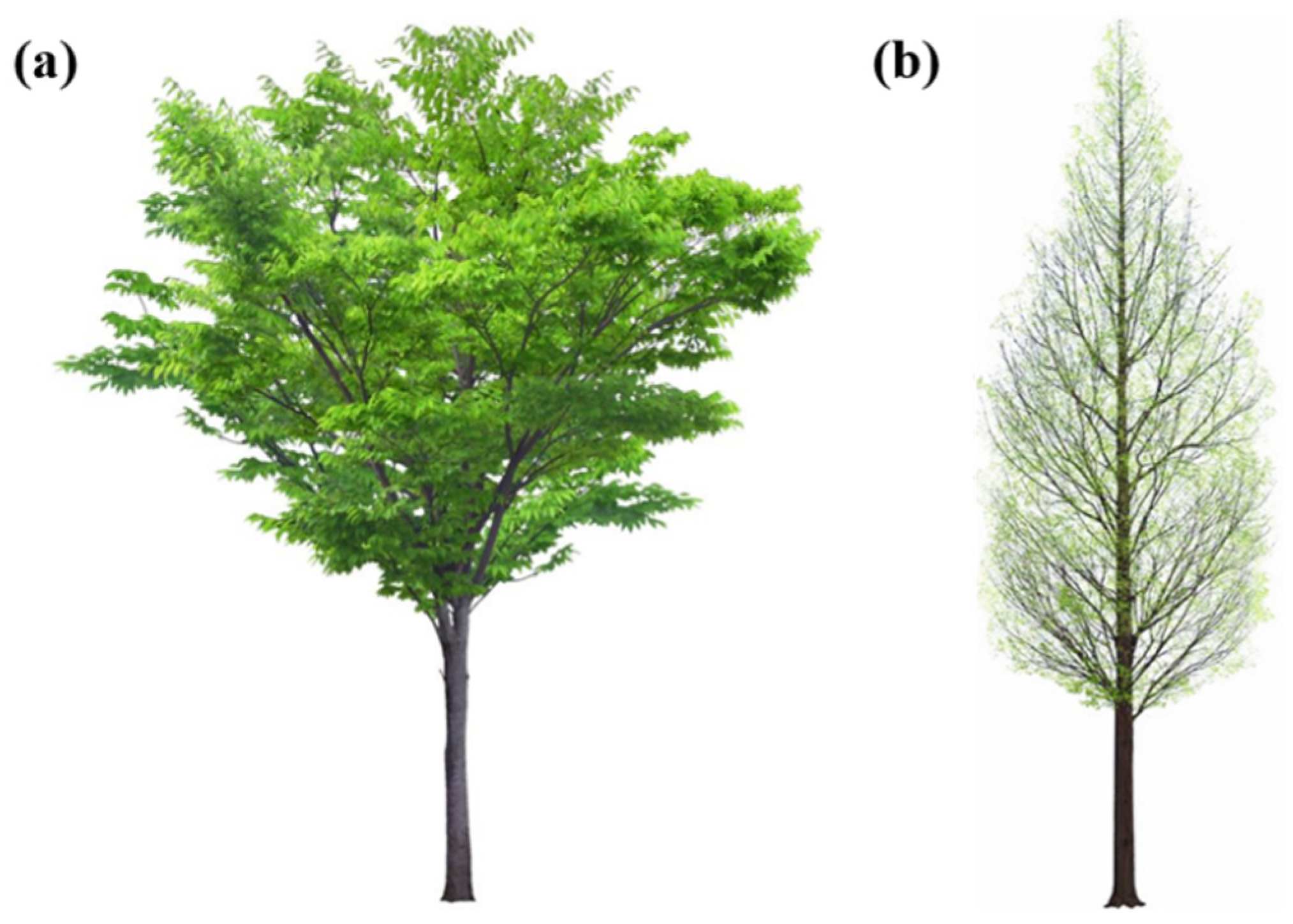
Figure 1. Different tree configurations, (a) decurrent tree with spreading form and no central trunk, and (b) excurrent tree with a central trunk.
Applsci 12 07432 g001
Figure 2. (a) Prototype [5], (b) skeleton with No. 1–10 branches, the knocking points (distributed every 20 cm along the trunk height) and accelerometer (at the trunk height of 0.5 m), (c) input signal from the force hammer, and (d) output signal from the accelerometer.
Applsci 12 07432 g002
Figure 3. Relationship of (a) density and (b) MOE between green wood and dry wood (12% moisture content).
Applsci 12 07432 g003
Figure 4. FRFs of the prototype at (a) north–south and (b) east–west directions, and first three mode shapes of the trunk at (c) north–south and (d) east–west directions.
Applsci 12 07432 g004
Figure 5. Relationship between fundamental trunk frequency ( f t r u n k 1 s t ) and total leaf mass ( m l e a f ).
Applsci 12 07432 g005
Figure 6. (a) Frequencies and (b) effective mass fraction of the first twenty-four modes, including mode shapes of modes (c) 1st, 2nd, (d) 3rd, 4th, and (e) 23rd, 24th.
Applsci 12 07432 g006
Figure 7. Eight configurations, C1 (a), C2 (b), C3 (c), C4 (d), C5 (e), C6 (f), C7 (g) and C8 (h) [5].
Applsci 12 07432 g007
Figure 8. (a) Crown profiles of the model and the prototype, (b) LAD and (c) cumulative LAI of the aeroelastic model for cases C3 to C8.
Applsci 12 07432 g008
Figure 9. (a) The profiles of non-dimensional mean velocity and turbulence intensity, and (b) the PSD function of streamwise velocities at reference height, for the wind tunnel terrain and the theoretical full-scale terrain from ESDU.
Applsci 12 07432 g009
Figure 10. (a) Drag coefficients of the aeroelastic model for cases C1 to C8 and other broad-leaved trees, including rose of Sharon, poplar trees, black cottonwood, trembling aspen, red alder, paper birch and bigleaf maple, and (b) crown deflection for case C8 at full-scale wind speeds of 0 m/s to 22.8 m/s.
Applsci 12 07432 g010aApplsci 12 07432 g010b
Figure 11. Variations of (a) speed specific drag ( F D / U 2 ) versus wind speed (U), and (b) total Vogel exponent versus ratio of frontal area between leaf and branch ( A l e a f / A b r a n c h ).
Applsci 12 07432 g011
Figure 12. Frequencies of the aeroelastic model in the along-wind and across-wind directions.
Applsci 12 07432 g012
Figure 13. Schematic of calculating damping of the aeroelastic model tree: (a) raw free vibration curve including (b) two frequency components can be separated into (c) free vibration curve at (d) crown frequency, and (e) free vibration curve at (f) trunk frequency, the variations of damping at (g) crown and (h) trunk frequencies versus the mean top-trunk displacement normalized by the height of the aeroelastic model ( d ¯ t / H ) in the along-wind direction.
Applsci 12 07432 g013
Table 1. Geometry dimensions of the prototype, FEM and the aeroelastic model.
ParametersPrototypeFEMAeroelastic Model
Total height (m)661
Trunk height (m)330.5
DBH (m)0.150.150.025
Crown height (m)330.5
Crown diameter (m)330.5
Table 2. Dimensions of branches and simplifications for FEM.
East–West DirectionNorth–South Direction D b
(cm)
L b
(m)
α b
(°)
β b
(°)
Simplification for FEM
Applsci 12 07432 i001 Applsci 12 07432 i0025.42.8890perpendicularity Applsci 12 07432 i003
Applsci 12 07432 i004 Applsci 12 07432 i0054.21.8090perpendicularity Applsci 12 07432 i006
Applsci 12 07432 i007 Applsci 12 07432 i0083.62.16450, 60, 120, 180, 240, 300 Applsci 12 07432 i009
Applsci 12 07432 i010 Applsci 12 07432 i011
Applsci 12 07432 i012 Applsci 12 07432 i0131.80.7200, 90 Applsci 12 07432 i014
Note: D b is the proximal diameter of branches connected to the main trunk, L b is the total length of branches, α b is the angle between the branch and horizontal plane in vertical plane, and β b is the anticlockwise angles between projections of branches in horizontal plane and north direction.
Table 3. Parameters of dynamic characteristics of the prototype and the aeroelastic model.
ParametersPrototypeAeroelastic Model (Full Scale)
Total leaf mass15.41 kg0–23.09 kg
Crown frequency1.49–1.83 Hz1.14–1.98 Hz
Trunk frequency5.18 Hz4.81–6.49 Hz
Crown damping0.06–0.08 [34]0.085
Trunk damping0.0540.033
Publisher’s Note: MDPI stays neutral with regard to jurisdictional claims in published maps and institutional affiliations.