Article

Active Disturbance Rejection Contouring Control of Robotic Excavators with Output Constraints and Sliding Mode Observer

School of Mechanical and Automotive Engineering, University of Ulsan, Ulsan 44610, Korea
*
Author to whom correspondence should be addressed.
Appl. Sci. 2022, 12(15), 7453; https://doi.org/10.3390/app12157453
Submission received: 30 June 2022 / Revised: 21 July 2022 / Accepted: 22 July 2022 / Published: 25 July 2022

Abstract

:
This paper proposes an active disturbance rejection contouring control scheme for robotic excavators suffering from model uncertainties, external disturbances, and unmeasurable states. A sliding mode observer (SMO) is firstly designed to precisely estimate both joint velocities and lumped uncertainties and disturbances. These estimations are then fed back into the main controller which is constructed based on the task coordinate frame (TCF) approach. Furthermore, to meet the requirements of high-accuracy control performance, the barrier Lyapunov function (BLF) is utilized in the control design together with the previous techniques, which guarantees the stability of the whole system. Finally, numerical simulation is conducted with a high-reliability excavator model to verify the effectiveness of the proposed control algorithm under various operating conditions. In future work, further practical problems will be conducted to realize the application of robotic excavators in construction.

1. Introduction

For a long time, excavators have played an important role in construction sites due to their mobility and versatility to complete earth-moving tasks. However, most excavators are manually operated, which not only challenges unskilled laborers but also causes occupational safety hazards. Furthermore, during excavators’ operation, repetitive and linear motions are continuously conducted, which is appropriate for robotic applications [1]. Therefore, in recent years, robotic excavators have been researched and developed by utilizing real-time algorithms for perception, task planning, motion planning, and control with input data supplied by multiple proprioceptive sensors, LiDAR, and cameras [2,3]. Among them, the position control algorithm is important to complete tasks, i.e., guaranteeing the tracking performance under difficulties such as system nonlinearities, model uncertainties, and external disturbances [4].
In recent years, together with other energy-saving and recovery purposes, many position control algorithms have been developed for robotic excavators, which vary from model-free approaches as proportional-integral (PI) control [5,6,7] and proportional-integral-derivative (PID) control [8], and model-based control approaches as backstepping control (BC) [9], sliding mode control (SMC) [7], and model predictive control (MPC) [8,10] with optimization performance [11]. Anyways, to increase the control performance which usually relies on excavation system model accuracy, data-driven approaches have also been proposed to re-construct the system model based on learning models with training progress [12,13,14]. However, only focusing on the tracking error as the ultimate performance index is not appropriate in the case of excavator operation since the work quality almost relies on the contouring performance. To deal with this problem, many contouring control approaches have been developed. For example, in [15,16], based on the kinematic transformation for the tracking error, the cross-coupled control (CCC) methods were developed together with the main position tracking control, which provided simple structures, but the final control performance was not reliable and accurate since the excavator model information was not utilized. In contrast, this information was integrated into the task coordinate frame (TCF) approach [4], which provided a general framework for further model-based control algorithms in order to separately regulate the contouring, tangential, and orientation errors. In [17], an MPC was also developed for the contouring control problem of excavators, which relies on the lifting-linearization method with the Koopman operator. Based on the linearized data-driven model of the excavator, the optimal control algorithm was derived to minimize the pre-defined cost function including contouring performance with other criteria. However, since this method requires many computational efforts, the realization of real-time performance in practical conditions will be a challenge.
Like the developments in model-based control approaches, uncertainties and disturbances must be considered in the control design for robotic excavators since these difficulties always exist and deteriorate the system performance during interaction with the environment. Therefore, uncertainties and disturbances attenuation techniques are important to guarantee high-accuracy control performance. Overall, two main approaches have been applied for general robotic applications, i.e., adaptive control and disturbance observer (DOB). For the adaptive control, it was originally proposed to deal with structured uncertainties, i.e., known uncertainty functions with unknown slow-varying parameters in linear regression form [18,19]. Moreover, this method was further extended to the adaptive mechanism with intelligent approximators such as neural networks (NNs) [20,21] or fuzzy logic systems (FLSs) [22,23], which can handle unstructured uncertainties. However, these approaches were not designed to deal with external disturbances due to the states-dependent characteristics. In contrast, disturbance observers (DOBs) have been proposed to deal with not only model uncertainties, but also external disturbances based on the assumption that their derivatives are bounded. Recent developments can be considered as the nonlinear disturbance observer (NDOB) [24,25] and time delay estimation (TDE) [26,27,28] which require states and their derivatives information to achieve high accuracy disturbance estimation performance. Overcoming this requirement, the extended-state observer (ESO) was developed to estimate both lumped disturbances and system states based on the augmented state mechanism [4,29]. However, the order of this observer was quite high, which may cause computational burdens and slow down the transient responses. A potential solution to deal with these difficulties is the sliding mode observer (SMO) which considers a similar problem, i.e., state estimation, based on the switching mechanism of the estimation errors [30]. Therefore, fast responses in the estimates can be guaranteed with robustness to changes in system dynamics. However, to the best of the authors’ knowledge, the SMO has not been applied for states and disturbances estimation in general robotic applications, especially excavator control design.
Beyond that, for further improvement of excavator control accuracy, i.e., guarantee predefined control criteria, many techniques which have been widely applied in robotic fields can be investigated as prescribed performance function (PPF) [31,32], barrier Lyapunov function (BLF) [29,33], and their variations [34,35]. However, until now, the application of these advanced techniques in the control design of robotic excavators was quite limited. In the authors′ previous work [4,36], the BLF is adopted to guarantee high accuracy contouring control performance and only PID is applied for the remaining performance indices, which does not fully cover the operation of the whole system. Therefore, to entirely specify the task quality, it is necessary to apply constraint techniques for all the criteria, i.e., contouring error, tangential error, and orientation error when synthesizing the control signal.
Based on the above-mentioned analysis, in this paper, an active disturbance rejection contouring control is proposed for robotic excavators. The main contribution relies on the development and implementation of an SMO, which is firstly designed to effectively estimate both system states and lumped disturbances and uncertainties during the operation of robotic excavators. These estimates are fed back into the main controller, which is designed based on the TCF approach to separate the tracking error into contouring error and the other error components. Finally, the prescribed performance is guaranteed for all system criteria based on the BLF. Simulation with a high-reliability excavator model is conducted to verify the proposed control performance.
The paper is organized as follows: In Section 2, the problem formulation is described. Section 3 explains the proposed SMO design. In Section 4, the design of the proposed control algorithm is presented. Numerical simulation is discussed in Section 5. Finally, Section 6 concludes this work.

2. Problem Formulation

The schematic diagram of the investigated excavator model is described in Figure 1. The operation is completed by the motions of three links including the boom, arm, and bucket. The end-effector position is presented by coordinates ( x , y , ϕ ) . For simplicity, the swing motion is omitted here. The excavator kinematics are clearly described in [4].
Based on Lagrangian mechanics, the excavator dynamics are expressed as
M ( q ) q ¨ + V ( q , q ˙ ) + G ( q ) + τ f = J a T u
where q R 3 is the vector of joint angles; M ( q ) R 3 × 3 , V ( q , q ˙ ) R 3 , and G ( q ) R 3 denotes the inertial matrix, centrifugal and Coriolis force, and gravity, respectively; J and J a are Jacobian matrices; τ f = J T ( q ) F d + J a T F f indicates the lumped disturbances and uncertainties where F d R 3 is the external torque/force vector acting on the bucket tips and F f represents uncertainties in the actuation system; u is the control signal, i.e., hydraulic actuation force.
To realize the design of the proposed SMO and main controller, the system dynamics are expressed in the following form:
x ˙ 1 = x 2 x ˙ 2 = f ( x 1 , x 2 ) + g ( x 1 ) u + d
where x 1 = q ,   x 2 = q ˙ ,   f ( x 1 , x 2 ) = M ( x 1 ) 1 [ V ( x 1 , x 2 ) + G ( x 1 ) ] , g ( x 1 ) = M ( x 1 ) 1 J a ( x 1 ) T , and d = M ( x 1 ) 1 τ f .
Assumption 1.
The vector of lumped uncertainties and disturbances is bounded, i.e., d Δ d where Δ d is a positive constant.
Assumption 2.
The Lipschitz condition holds for the nonlinear term f ( x 1 , x 2 ) as follows:
f ( x 1 , x 2 ) f ( x 1 , x 2 + Δ x 2 ) α f Δ x 2
where α f is a positive constant.
Remark 1.
Assumption 1 is usually applied for sliding mode techniques, which is reasonable since the physical control system cannot handle unbounded uncertainties and disturbances. Besides, Assumption 2 is necessary to overcome the effect of nonlinearities on the observation and control performance.
Remark 2.
With joint angle measurement, the problem is how to construct an observer that effectively estimates both joint velocities and lumped uncertainties and disturbances in the excavation system. Based on that, the control algorithm needs to be derived to guarantee high-accuracy control performance, especially contouring control performance with prescribed performance.

3. SMO Design

The proposed SMO is expressed as follows:
{ s ˙ 1 = s 2 + v s ˙ 2 = f ( x 1 , s 2 ) + g ( x 1 ) u + ω v
where s 1 and s 2 are the states of the observer, and ω is the observer gain. The symbol v denotes a switching function of the observation error, which is defined by
v = { η ( x 1 s 1 ) x 1 s 1     if x 1 s 1 0 0 otherwise
where η is a positive parameter.
Theorem 1.
Based on Assumptions 1 and 2, the proposed SMO (4) ensures arbitrarily bounded estimation performance for the system (2) if the observer parameters are selected with large enough values.
Proof of Theorem 1.
Denote the error term s ˜ = x s . Subtracting both sides of (4) from those of (2), the error dynamics are expressed as follows:
s ˜ ˙ 1 = s ˜ 2 v s ˜ ˙ 2 = f ˜ + d ω v
Define a Lyapunov function V s 1 = 1 / 2 s ˜ 1 T s ˜ 1 . Differentiating it and substituting (5) into, it becomes
V ˙ s 1 = s ˜ 1 ( s ˜ 2 v ) s ˜ 1 ( η s ˜ 2 )
where the observer parameter η is selected with a large enough value so that there exists a positive constant η 0 satisfying s ˜ 2 η η 0 . Therefore, one obtains
V ˙ s 1 2 η 0 V s 1
Based on this, s 1 converges to zero in finite time. After that, from the first equation of (6), it is observed that the switching function v is equivalent to the error s ˜ 2 . Substituting it into the second equation of (6), the equivalent error dynamics are given by
s ˜ ˙ 2 = f ˜ + d ω s ˜ 2
Another Lyapunov function is designed as V s 2 = 1 / 2 s ˜ 2 T s ˜ 2 . The derivative of it is derived by
V ˙ s 2 = s ˜ 2 T ( f ˜ + d ω s ˜ 2 ) ω s ˜ 2 T s ˜ 2 + s ˜ 2 T s ˜ 2 + 1 2 f ˜ T f ˜ + 1 2 d T d
Combining with Assumptions 1 and 2, the following inequality holds
V ˙ s 2 ( ω 1 2 α f 2 1 ) s ˜ 2 T s ˜ 2 + 1 2 Δ d 2 λ s 2 V s 2 + Δ s 2
where λ s 2 = ( 2 ω α f 2 2 ) and Δ s 2 = 0.5 Δ d 2 .
From this, the proof of Theorem 1 is completed. □
The joint velocity and disturbance estimations are expressed as follows:
x ^ 2 = s 2 + v d ^ = ω 1 v
The first estimation is derived since x ^ 2 = s ˙ 1 converges to x 2 after the convergence time of s ˜ 1 . Similarly, d can be estimated by d ^ when comparing (2) and (4).
Remark 3.
A modified switching function is designed to attenuate the chattering effects on the estimated values in (12) as
v mod = η ( x 1 s 1 ) x 1 s 1 + ε v  
where ε v is a positive constant.

4. Control Design

Based on the estimates from the SMO, the main controller is constructed with the Lyapunov function in order to guarantee prescribed performance in all error components, which is different from the authors’ previous work. The control diagram is shown in Figure 2.
The control signal is proposed as follows:
u = J a T ( q ) ( V ( q , q ˙ ^ ) + G ( q ) + M ( q ) d ^ + u 1 ) u 1 = M ( q ) J 1 ( q ) J ˙ ( q , q ˙ ^ ) q ˙ ^ M ( q ) J 1 ( q ) T 1 u 2 + M ( q ) T 1 r ¨ d
where r d denotes the reference trajectory of the end-effector r = ( x , y , ϕ ) , u 2 is an auxiliary control signal to be designed later, and T is the task coordinate transformation matrix, which denotes the following relation:
ε = Te
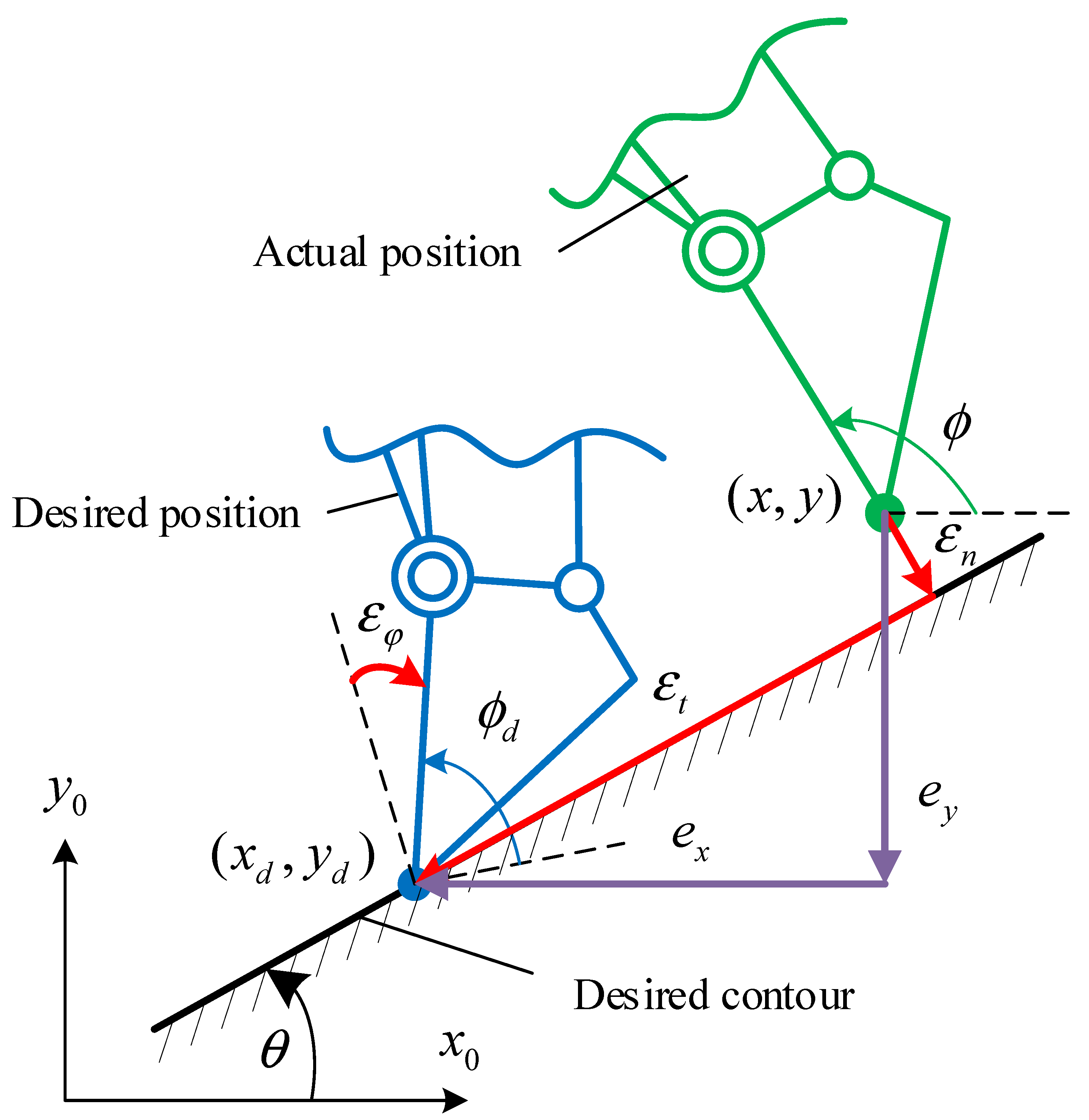
where ε = [ ε n , ε t , ε ϕ ] T is a new presentation of the original tracking error e = r d r , which includes the normal, tangential, and orientation tracking error components, respectively. The transformation matrix T is calculated based on the slope angle θ of the desired contour as shown in Figure 3.
In the case that linear contour is adopted, i.e., T is constant, from (14) and (15), the error dynamics is derived as
ε ¨ = u 2 + f d
where f d is the lumped error components including velocity and disturbance estimation errors of the SMO, which is bounded, i.e., f d Δ f , Δ f > 0 .
The output constraint is pre-defined as follows:
b n ( t ) ε n b n ( t ) b t ( t ) ε t b t ( t ) b ϕ ( t ) ε ϕ b ϕ ( t )
where b i ( t ) are predefined limits.
To maintain these prescribed performances during operation, the auxiliary control signal u 2 is designed by
u 2 i = α ˙ i ε i b i ( t ) 2 ε i 2 + k 2 i z i ( i = n , t , ϕ )
where z i = α i ε ˙ i , α i = ( k 1 i + λ i ( t ) ) ε i , λ i ( t ) = { b ˙ i ( t ) 2 / b i ( t ) 2 + β } , k 1 i and k 2 i are control gains, and β is a positive constant.
Theorem 2.
For the system (1), the proposed control algorithm (14), (18) together with the SMO (4), (12) guarantees prescribed performance on both contouring, tangential, and orientation error components under the effects of lumped uncertainties and disturbances.
Proof of Theorem 2.
Lyapunov functions are defined as follows:
V i = 1 2 ln ( b i 2 ( t ) b i 2 ( t ) ε i 2 ) + 1 2 z i 2 ( i = n , t , ϕ )
Taking derivatives of them and substituting (16) and (18) into them, one obtains
V ˙ i = ε i b i 2 ( t ) ε i 2 ( ε ˙ i ε i b ˙ i ( t ) b i ( t ) ) + z i z ˙ i = ε i b i 2 ( t ) ε i 2 ( α i ε i b ˙ i ( t ) b i ( t ) ) ε i z i b i 2 ( t ) ε i 2 + z i ( α ˙ i u 2 i f d i ) k 1 i ε i 2 b i 2 ( t ) ε i 2 k 2 i z i 2 + z i f d i k 1 i ln ( b i 2 ( t ) b i 2 ( t ) ε i 2 ) ( k 2 i 1 2 ) z i 2 + 1 2 f d i 2 λ i V i + Δ i
where λ i = 2 min ( k 1 i , k 2 i 0.5 ) and Δ i = 0.5 Δ f 2 .
From this, the stability of each error component is proved. Based on that, the stability of the total system is guaranteed. Therefore, the proof is completed. □

5. Numerical Simulation

5.1. Simulation Setup

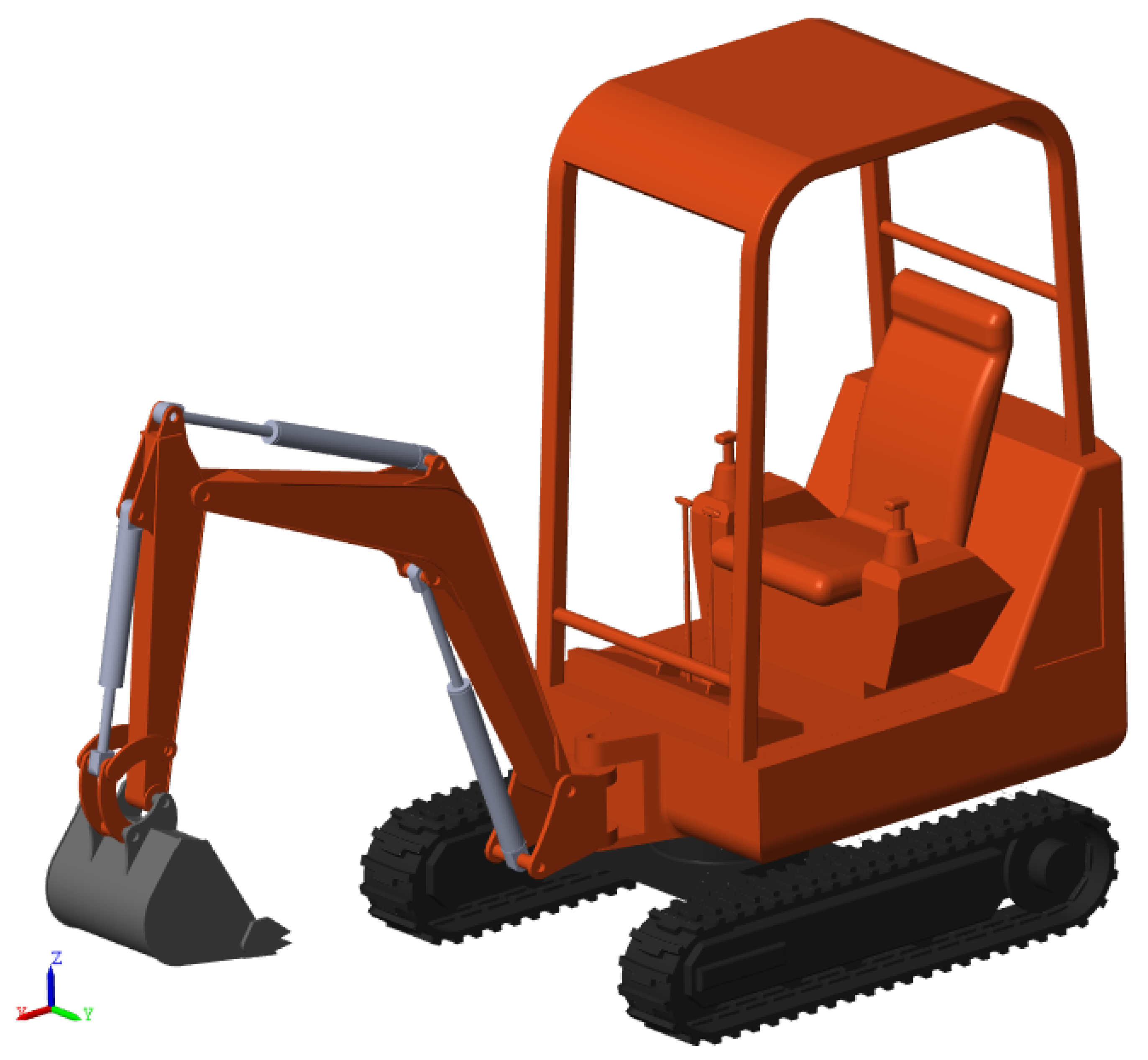
In this section, a mini-excavator model is utilized to verify the effectiveness of the proposed algorithm, as shown in Figure 4. The simulation is conducted in MATLAB Simulink 2022a environment with sampling times of 1ms for the main controller and observer and 0.1ms for the excavator. Dynamic parameters are given in Table 1.

5.2. Controller for Comparision

Three controllers are investigated to verify the contribution of the paper as follows:
-
The ESO-based contouring controller (ESOC): This controller was constructed in our previous work [4] with the ESO to estimate joint velocities and lumped disturbances. The prescribed control performance is only guaranteed for the contouring error. For the remaining tangential and orientation errors, only the proportional-derivative (PD) control law is applied as follows:
u 2 i = k d i ε ˙ i k p i ε i ( i = t , ϕ )
where k d i and k p i are the derivative and proportional gains, respectively.
-
The SMO-based contouring controller (SMOC): This controller has the same structure as the ESO-based controller. However, the ESO is replaced by the SMO to verify the proposed observer.
-
The proposed controller: The controller is similar to the SMO-based controller. Nevertheless, the prescribed performance is applied for all the error components. Depending on the priority, the constraint level can be adjusted.
For a fair comparison, equivalent control parameters are selected for both controllers, as shown in Table 2.

5.3. Simulation Results

5.3.1. Case 1: Horizontal Contour

In this case study, a horizontal desired contour is selected to verify the effectiveness of the proposed controller compared to the ESOC and the SMOC. In Figure 5a, it is observed that the proposed controller and the SMOC provide high accuracy contouring control performance within prescribed bounds while the ESOC cannot achieve that, which shows the superiority of the proposed SMO compared to the ESO. Similar results are described in Figure 5b,c for the tangential errors and contouring errors, respectively. However, only the proposed controller guarantees the prescribed performance in these error components since the model-based control with BLF is applied here compared to the PD control of the ESOC and SMOC. Anyways, the contour shapes are given in Figure 5d, which once again states the dominations of the proposed control algorithm with the other ones.
For further analysis of these results, the disturbance estimation performances of the proposed SMO and ESO in terms of the boom, arm, and bucket are presented in Figure 6. One observes that the SMO in the proposed controller shows the fastest transient responses when abrupt disturbances occur compared to the SMO in the SMOC and the ESO, which explains the ability to keep the errors component inside the bounds of the proposed controller as mentioned above. In the steady-states, the ESO even shows better disturbance estimation compared to the other ones, but the tracking performance cannot be maintained since it already violates constraints at the last transient times.
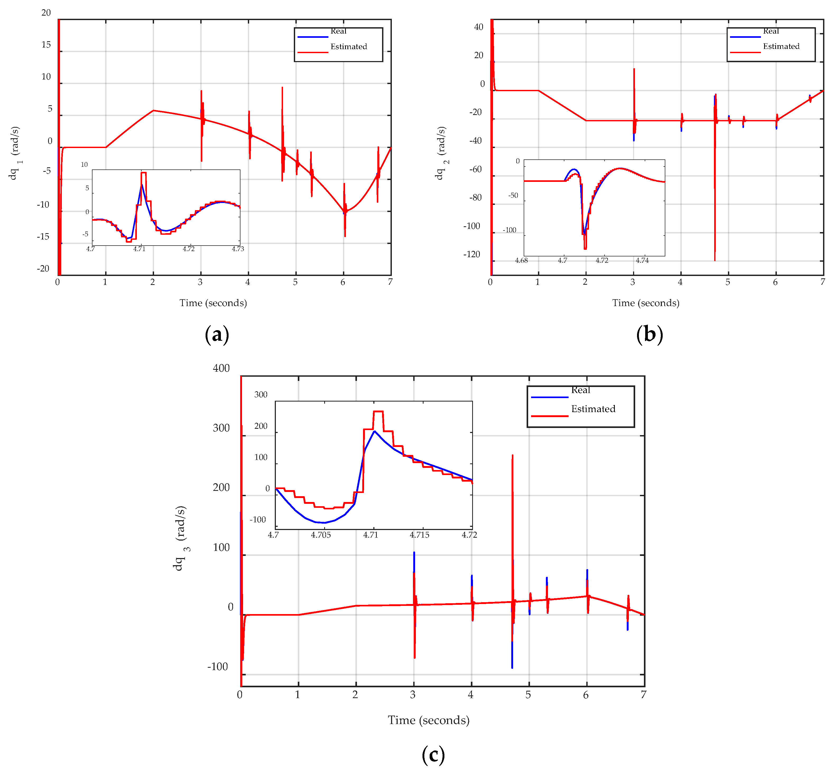
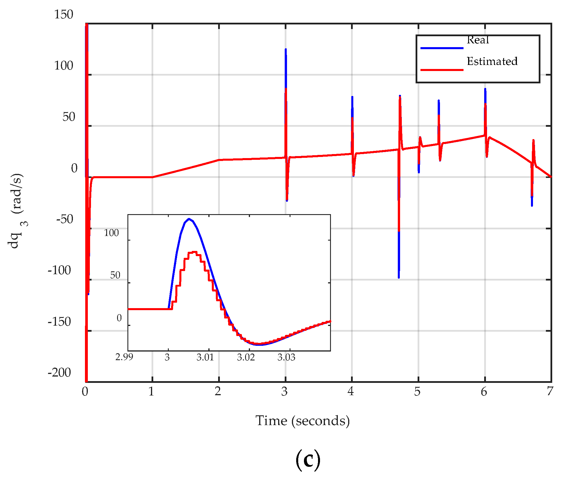
In addition, Figure 7 describes the high-accuracy velocity estimation performance of the proposed SMO during the operation, which partly contributes to the final tracking performance of the proposed control algorithm in Figure 5.
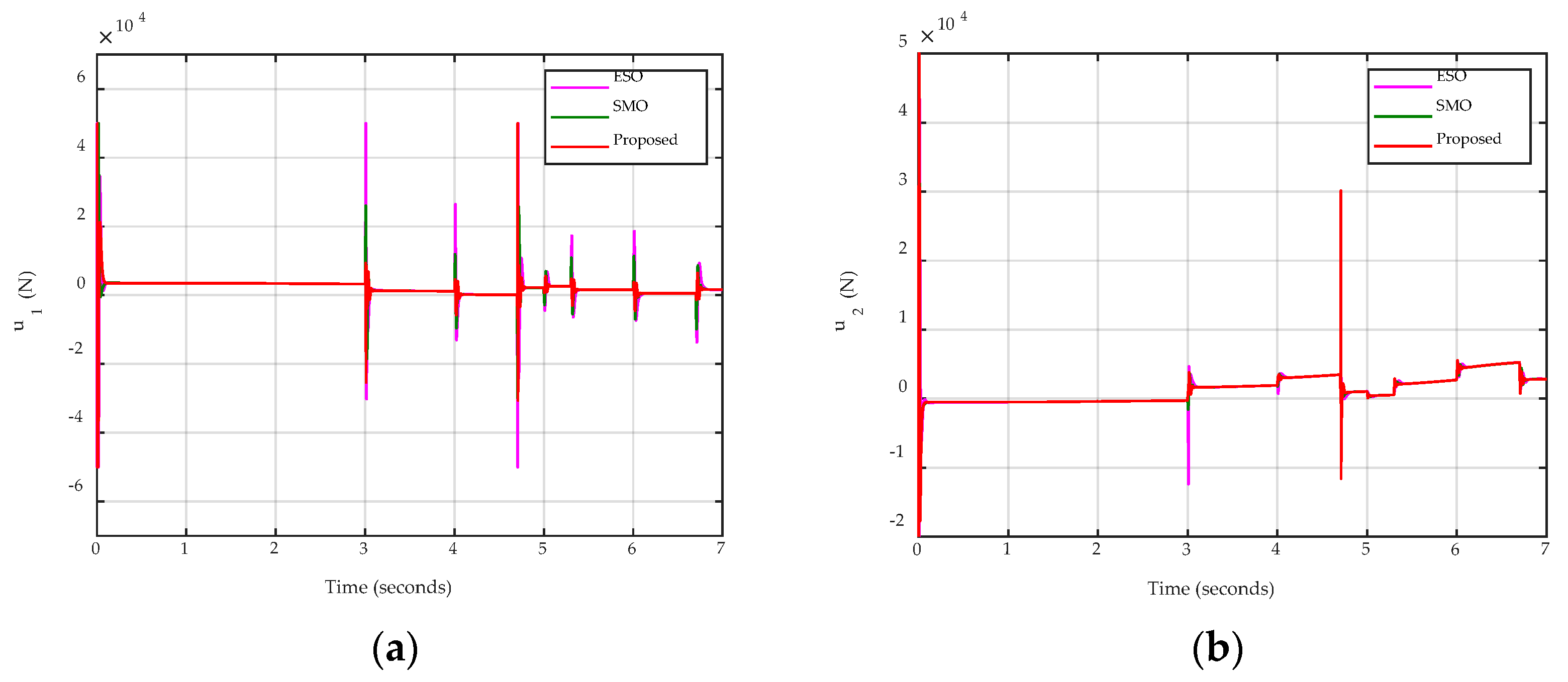
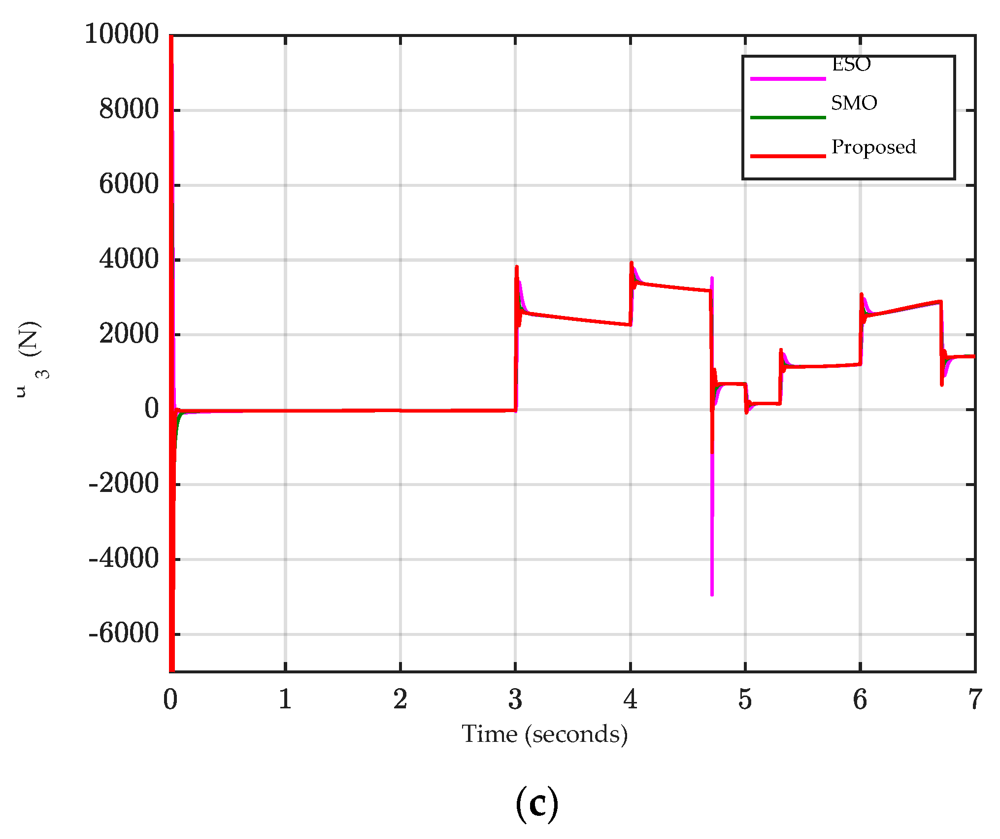
Finally, the control signals of both controllers are shown in Figure 8. Overall, at the steady state, there is not so much difference in the control signals of the SMO-based controllers and the ESOC. However, in the transient response, since the ESOC reacts slower with changes in disturbance and provides the worst tracking errors, it generates the highest control signal compared to the remaining ones.

5.3.2. Case 2: Sloped Contour

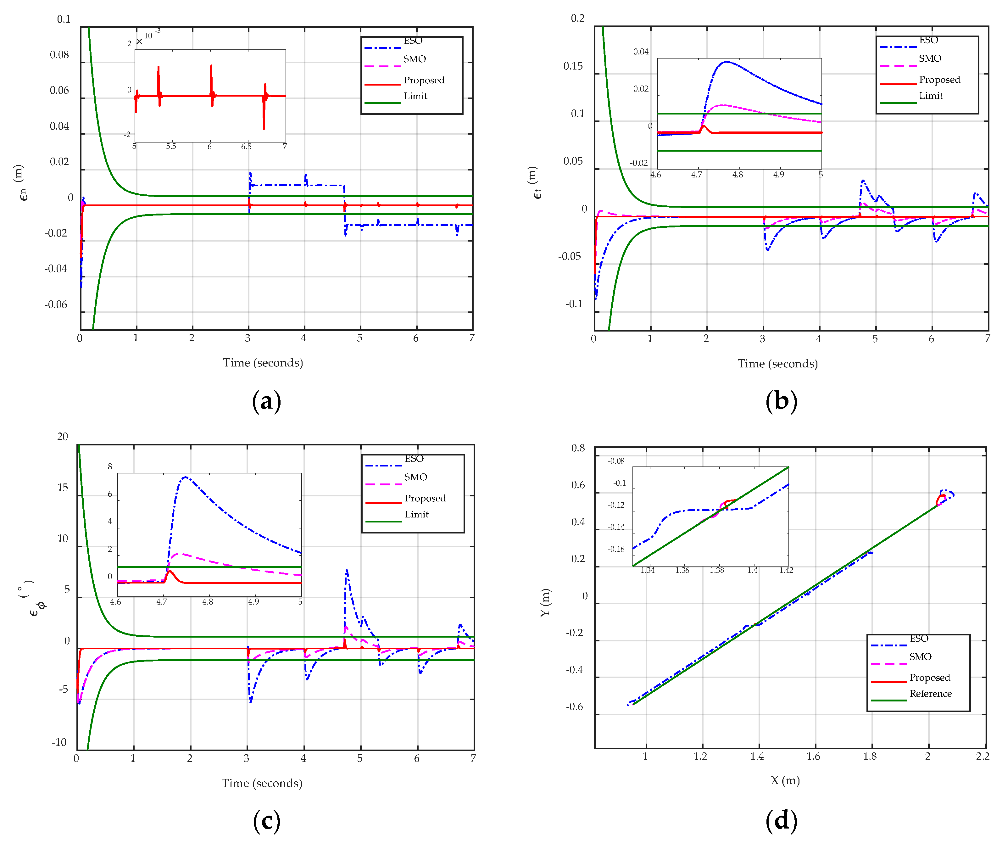
To further investigate the performance of the proposed control algorithm, a sloped contour with 45 degrees is selected in the simulation. Overall, similar results are observed compared to those of Case 1. The contouring error, tangential error, orientation error, and contour shape are described in Figure 9a–d, respectively, which indicates the superiority of the proposed control algorithm.
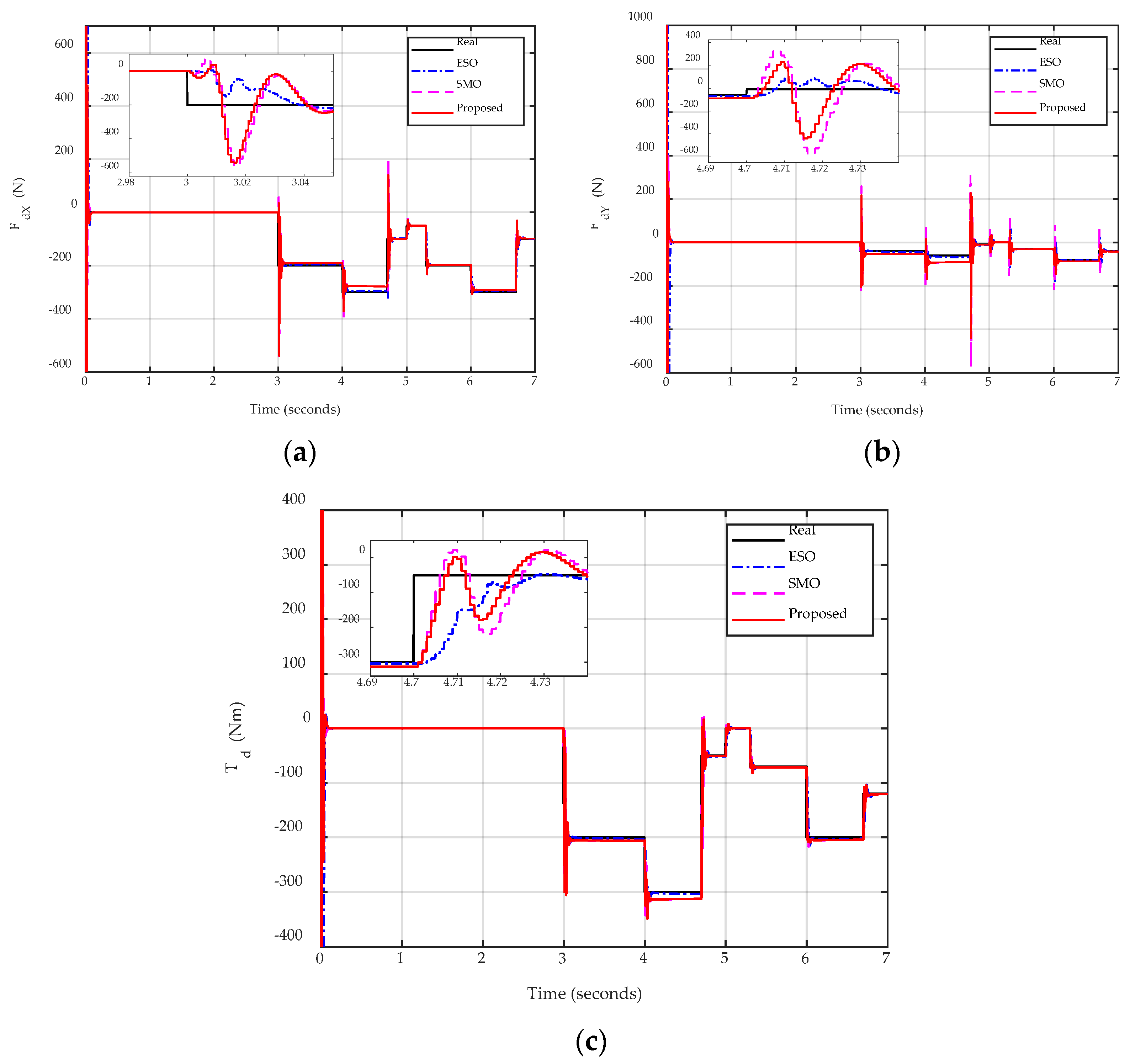
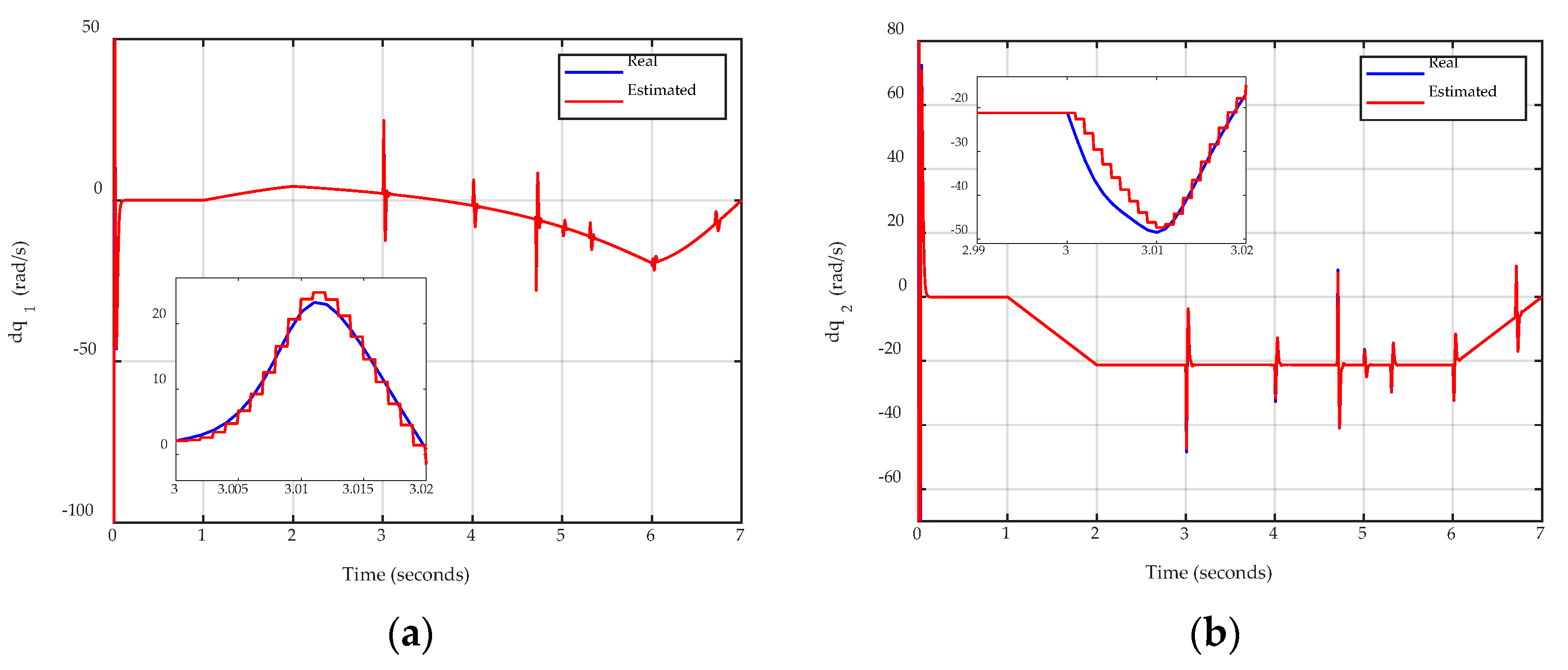
Moreover, the disturbance and velocity estimation performances are given in Figure 10 and Figure 11, which once again emphasize the importance of the proposed SMO in the final control performance under different operating conditions.

6. Conclusions

In this paper, an SMO-based contouring controller is developed for robotic excavators to achieve high-accuracy contouring control performance during operation. The SMO is designed for the first time to effectively estimate not only the lumped uncertainties and disturbances but also the unmeasurable joint velocities, especially when abrupt disturbances occur, which directly contribute to the final control performances. Furthermore, to guarantee better performance compared to previous works, the BLF technique is integrated into the control design for both error components. Simulation results verify the effectiveness of the proposed observer and controller compared to the ESO and the ESO-based controller. In future work, further practical problems will be considered in this SMO-based contouring control scheme with experiment verification.

Author Contributions

K.K.A. was the supervisor, providing funding and administrating the project, and he reviewed and edited the manuscript. H.V.D. performed investigation, proposed methodology, analysis, and validations using MATLAB/Simulink software for simulations and wrote the original manuscript. All authors have read and agreed to the published version of the manuscript.

Funding

This research was supported by Basic Science Program through the National Research Foundation of Korea (NRF) funded by the Ministry of Science and ICT, South Korea (NRF 2020R1A2B5B03001480) and “Regional Innovation Strategy (RIS)” through the National Research Foundation of Korea (NRF) funded by the Ministry of Education (MOE) (2021RIS-003).

Institutional Review Board Statement

Not applicable.

Informed Consent Statement

Not applicable.

Data Availability Statement

Not applicable.

Conflicts of Interest

The authors declare no conflict of interest.

References

  1. Azar EA, K.V. Earthmoving equipment automation: A review of technical advances and future outlook. J. Inf. Technol. Constr. 2017, 22, 247–265. [Google Scholar]
  2. An Autonoumous Excavator System for Material Loading Tasks. Available online: http://research.baidu.com/Blog/index-view?id=159 (accessed on 15 May 2022).
  3. Built Robotics Aspires to Automatize Industry. Available online: https://www.constructionequipmentguide.com/built-robotics-aspires-to-automatize-industry/50965 (accessed on 15 May 2022).
  4. Dao, H.V.; Na, S.; Nguyen, D.G.; Ahn, K.K. High accuracy contouring control of an excavator for surface flattening tasks based on extended state observer and task coordinate frame approach. Autom. Constr. 2021, 130, 103845. [Google Scholar] [CrossRef]
  5. Xu, J.; Yoon, H.-S. Vision-based estimation of excavator manipulator pose for automated grading control. Autom. Constr. 2019, 98, 122–131. [Google Scholar] [CrossRef]
  6. Zhang, X.; Qiao, S.; Quan, L.; Ge, L. Velocity and Position Hybrid Control for Excavator Boom Based on Independent Metering System. IEEE Access 2019, 7, 71999–72011. [Google Scholar] [CrossRef]
  7. Fu, S.; Ren, H.; Lin, T.; Zhou, S.; Chen, Q.; Li, Z. SM-PI Control Strategy of Electric Motor-Pump for Pure Electric Construction Machinery. IEEE Access 2020, 8, 100241–100250. [Google Scholar] [CrossRef]
  8. Ranjan, P.; Wrat, G.; Bhola, M.; Mishra, S.K.; Das, J. A novel approach for the energy recovery and position control of a hybrid hydraulic excavator. ISA Trans 2020, 99, 387–402. [Google Scholar] [CrossRef] [PubMed]
  9. Bao, R.; Wang, Q.; Wang, T. Energy-Saving Trajectory Tracking Control of a Multi-Pump Multi-Actuator Hydraulic System. IEEE Access 2020, 8, 179156–179166. [Google Scholar] [CrossRef]
  10. Bender, F.A.; Goltz, S.; Braunl, T.; Sawodny, O. Modeling and Offset-Free Model Predictive Control of a Hydraulic Mini Excavator. IEEE Trans. Autom. Sci. Eng. 2017, 14, 1682–1694. [Google Scholar] [CrossRef]
  11. Kim, K.; Kim, M.; Kim, D.; Lee, D. Modeling and velocity-field control of autonomous excavator with main control valve. Automatica 2019, 104, 67–81. [Google Scholar] [CrossRef]
  12. Sandzimier, R.J.; Asada, H.H. A Data-Driven Approach to Prediction and Optimal Bucket-Filling Control for Autonomous Excavators. IEEE Robot. Autom. Lett. 2020, 5, 2682–2689. [Google Scholar] [CrossRef]
  13. Egli, P.; Hutter, M. A General Approach for the Automation of Hydraulic Excavator Arms Using Reinforcement Learning. IEEE Robot. Autom. Lett. 2022, 7, 5679–5686. [Google Scholar] [CrossRef]
  14. Lee, M.; Choi, H.; Kim, C.; Moon, J.; Kim, D.; Lee, D. Precision Motion Control of Robotized Industrial Hydraulic Excavators via Data-Driven Model Inversion. IEEE Robot. Autom. Lett. 2022, 7, 1912–1919. [Google Scholar] [CrossRef]
  15. Lee, C.S.; Bae, J.; Hong, D. Contour control for leveling work with robotic excavator. Int. J. Precis. Eng. Manuf. 2013, 14, 2055–2060. [Google Scholar] [CrossRef]
  16. Wang, D.; Zheng, L.; Yu, H.; Zhou, W.; Shao, L. Robotic excavator motion control using a nonlinear proportional-integral controller and cross-coupled pre-compensation. Autom. Constr. 2016, 64, 1–6. [Google Scholar] [CrossRef]
  17. Sotiropoulos, F.E.; Asada, H.H. Dynamic Modeling of Bucket-Soil Interactions Using Koopman-DFL Lifting Linearization for Model Predictive Contouring Control of Autonomous Excavators. IEEE Robot. Autom. Lett. 2022, 7, 151–158. [Google Scholar] [CrossRef]
  18. Wang, H. Adaptive Control of Robot Manipulators with Uncertain Kinematics and Dynamics. IEEE Trans. Autom. Control 2017, 62, 948–954. [Google Scholar] [CrossRef] [Green Version]
  19. Yang, C.; Jiang, Y.; He, W.; Na, J.; Li, Z.; Xu, B. Adaptive Parameter Estimation and Control Design for Robot Manipulators With Finite-Time Convergence. IEEE Trans. Ind. Electron. 2018, 65, 8112–8123. [Google Scholar] [CrossRef]
  20. Li, Y.; Wang, Q. Adaptive neural finite-time trajectory tracking control of hydraulic excavators. Proc. Inst. Mech. Eng. I J. Syst. Control Eng. 2018, 232, 909–925. [Google Scholar] [CrossRef]
  21. He, W.; Huang, B.; Dong, Y.; Li, Z.; Su, C.Y. Adaptive Neural Network Control for Robotic Manipulators With Unknown Deadzone. IEEE Trans. Cybern. 2018, 48, 2670–2682. [Google Scholar] [CrossRef]
  22. Van, M.; Ge, S.S. Adaptive Fuzzy Integral Sliding Mode Control for Robust Fault Tolerant Control of Robot Manipulators with Disturbance Observer. IEEE Trans. Fuzzy Syst. 2020, 29, 1284–1296. [Google Scholar] [CrossRef] [Green Version]
  23. Yilmaz, B.M.; Tatlicioglu, E.; Savran, A.; Alci, M. Self-Adjusting Fuzzy Logic Based Control of Robot Manipulators in Task Space. IEEE Trans. Ind. Electron. 2022, 69, 1620–1629. [Google Scholar] [CrossRef]
  24. Dinh, T.X.; Thien, T.D.; Anh, T.H.V.; Ahn, K.K. Disturbance Observer Based Finite Time Trajectory Tracking Control for a 3 DOF Hydraulic Manipulator Including Actuator Dynamics. IEEE Access 2018, 6, 36798–36809. [Google Scholar] [CrossRef]
  25. Truong, H.V.A.; Tran, D.T.; To, X.D.; Ahn, K.K.; Jin, M. Adaptive Fuzzy Backstepping Sliding Mode Control for a 3-DOF Hydraulic Manipulator with Nonlinear Disturbance Observer for Large Payload Variation. Appl. Sci. 2019, 9, 3290. [Google Scholar] [CrossRef] [Green Version]
  26. Kim, J.; Jin, M.; Choi, W.; Lee, J. Discrete time delay control for hydraulic excavator motion control with terminal sliding mode control. Mechatronics 2019, 60, 15–25. [Google Scholar] [CrossRef]
  27. Lee, J.; Chang, P.H.; Jin, M. Adaptive Integral Sliding Mode Control with Time-Delay Estimation for Robot Manipulators. IEEE Trans. Ind. Electron. 2017, 64, 6796–6804. [Google Scholar] [CrossRef]
  28. Roy, S.; Kar, I.N.; Lee, J.; Jin, M. Adaptive-Robust Time-Delay Control for a Class of Uncertain Euler–Lagrange Systems. IEEE Trans. Ind. Electron. 2017, 64, 7109–7119. [Google Scholar] [CrossRef]
  29. Tran, D.T.; Jin, M.; Ahn, K.K. Nonlinear Extended State Observer Based on Output Feedback Control for a Manipulator with Time-Varying Output Constraints and External Disturbance. IEEE Access 2019, 7, 156860–156870. [Google Scholar] [CrossRef]
  30. Christopher Edwards, S.K.S. Sliding Mode Control: Theory and Applications; CRC Press: Boca Raton, FL, USA, 1998; p. 237. [Google Scholar]
  31. Guo, Q.; Zhang, Y.; Celler, B.G.; Su, S.W. Neural Adaptive Backstepping Control of a Robotic Manipulator with Prescribed Performance Constraint. IEEE Trans. Neural Netw. Learn. Syst. 2019, 30, 3572–3583. [Google Scholar] [CrossRef]
  32. Shojaei, K.; Kazemy, A.; Chatraei, A. An Observer-Based Neural Adaptive PID2 Controller for Robot Manipulators Including Motor Dynamics with a Prescribed Performance. IEEE/ASME Trans. Mechatron. 2021, 26, 1689–1699. [Google Scholar] [CrossRef]
  33. Ma, Z.; Huang, P. Adaptive Neural-Network Controller for an Uncertain Rigid Manipulator with Input Saturation and Full-Order State Constraint. IEEE Trans. Cybern. 2020, 52, 2907–2915. [Google Scholar] [CrossRef]
  34. Huang, D.; Yang, C.; Pan, Y.; Cheng, L. Composite Learning Enhanced Neural Control for Robot Manipulator with Output Error Constraints. IEEE Trans. Ind. Inform. 2021, 17, 209–218. [Google Scholar] [CrossRef]
  35. Yang, C.; Huang, D.; He, W.; Cheng, L. Neural Control of Robot Manipulators with Trajectory Tracking Constraints and Input Saturation. IEEE Trans. Neural Netw. Learn. Syst. 2021, 32, 4231–4242. [Google Scholar] [CrossRef]
  36. Dao, H.V.; Ahn, K.K. Task Coordinate Frame-Based Contouring Control of An Excavator with Sliding Mode Observer and Prescribed Performance. In Proceedings of the 2021 24th International Conference on Mechatronics Technology (ICMT), Singapore, 18–22 December 2021; pp. 1–6. [Google Scholar]
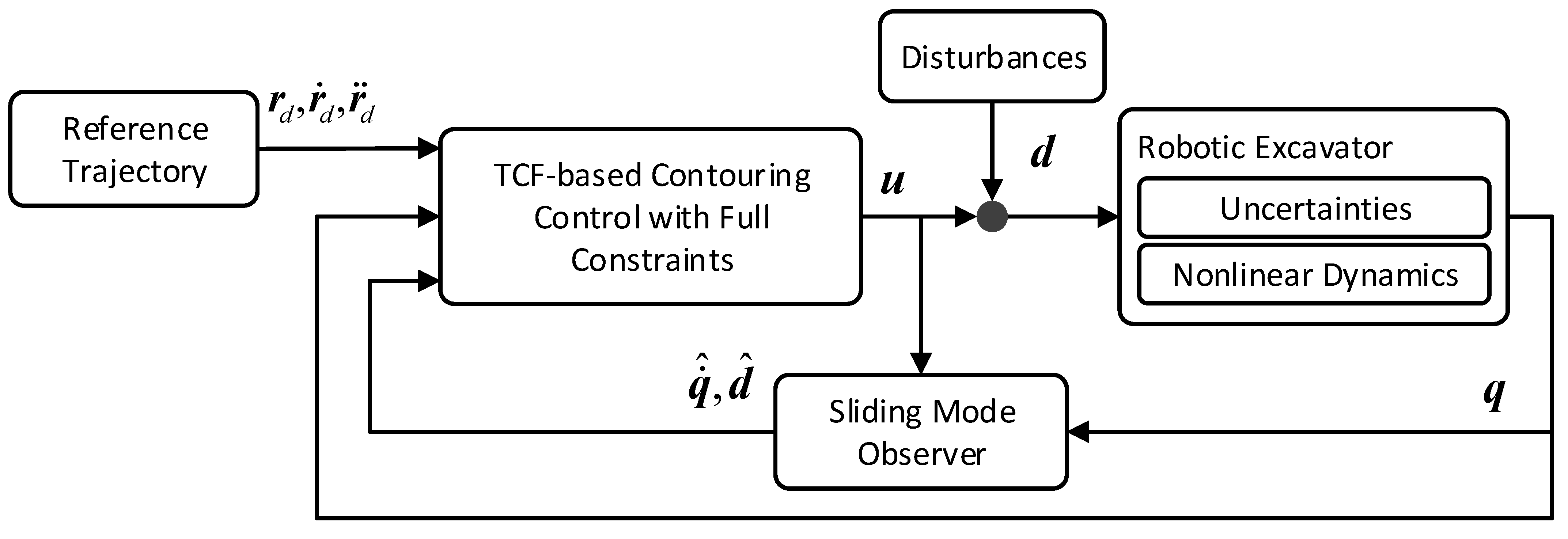
Figure 1. Excavator model [4], Reprinted/adapted with permission from Ref. [4]. 2021, Elsevier.
Applsci 12 07453 g001
Figure 2. Control schematics.
Applsci 12 07453 g002
Figure 3. Illustration of the error transformation mechanism [4], Reprinted/adapted with permission from Ref. [4]. 2021, Elsevier.
Applsci 12 07453 g003
Figure 4. Investigated robotic excavator model [4], Reprinted/adapted with permission from Ref. [4]. 2021, Elsevier.
Applsci 12 07453 g004
Figure 5. Control performance in terms of (a) contouring error, (b) tangential error, (c) orientation error, and (d) contour shape in Case 1.
Applsci 12 07453 g005
Figure 6. Estimation performance of (a) force disturbance in the x-direction, (b) force disturbance in the y-direction, and (c) torque disturbance in Case 1.
Applsci 12 07453 g006
Figure 7. Velocity estimation performance of (a) boom, (b) arm, and (c) bucket in Case 1.
Applsci 12 07453 g007
Figure 8. Control signals of (a) boom, (b) arm, and (c) bucket in Case 1.
Applsci 12 07453 g008aApplsci 12 07453 g008b
Figure 9. Control performance in terms of (a) contouring error, (b) tangential error, (c) orientation error, and (d) contour shape in Case 2.
Applsci 12 07453 g009
Figure 10. Estimation performance of (a) force disturbance in the x-direction, (b) force disturbance in the y-direction, and (c) torque disturbance in Case 2.
Applsci 12 07453 g010
Figure 11. Velocity estimation performance of (a) boom, (b) arm, and (c) bucket in Case 2.
Applsci 12 07453 g011aApplsci 12 07453 g011b
Table 1. Model parameter [4], Reprinted/adapted with permission from Ref. [4]. 2021, Elsevier.
ParameterDescriptionValueUnit
m 1 Mass of boom36.863kg
m 2 Mass of arm13.138kg
m 3 Mass of bucket9.008kg
I z 1 Mass moment of inertial of the boom7,306,759.708kgmm2
I z 2 Mass moment of inertial of the arm1,178,748.843kgmm2
I z 3 Mass moment of inertial of the bucket348,927.380kgmm2
r c 1 Center of mass of the boom[848.173, 213.106, 2.615] Tmm
r c 2 Center of mass of the arm[336.525, 65.798, −0.000] Tmm
r c 3 Center of mass of the bucket[210.471, 154.244, 0.082] Tmm
L 1 Length of boom1692mm
L 2 Length of arm851mm
L 3 Length of bucket580mm
To test the control performance, multi-step disturbances, i.e., interaction forces and torques with the environment, are added during the simulation. Moreover, simulation results with different desired contours, i.e., horizontal and slope contours, are also investigated.
Table 2. Control parameters.
ControllerParameters
ESOC k 1 n = 100 , k 2 n = 100 , β n = 0.1 , k d t = 50 , k p t = 200 , k d ϕ = 100 , k p ϕ = 500 , ω = 200
SMOC k 1 n = 100 , k 2 n = 100 , β n = 0.1 , k d t = 50 , k p t = 200 , k d ϕ = 100 , k p ϕ = 500 , ω = 200 , η = 150 , ε v = 0.3
Proposed controller k 1 n = k 1 t = k 1 ϕ = 100 , k 2 n = k 2 t = k 2 ϕ = 100 , β n = β t = 0.1 , β ϕ = 0.2 , ω = 200 , η = 150 , ε v = 0.3
Publisher’s Note: MDPI stays neutral with regard to jurisdictional claims in published maps and institutional affiliations.