
Study on Share Rate of Support Structure for Super-Large Span Twin Tunnels with Small Interval

Abstract
:1. Introduction
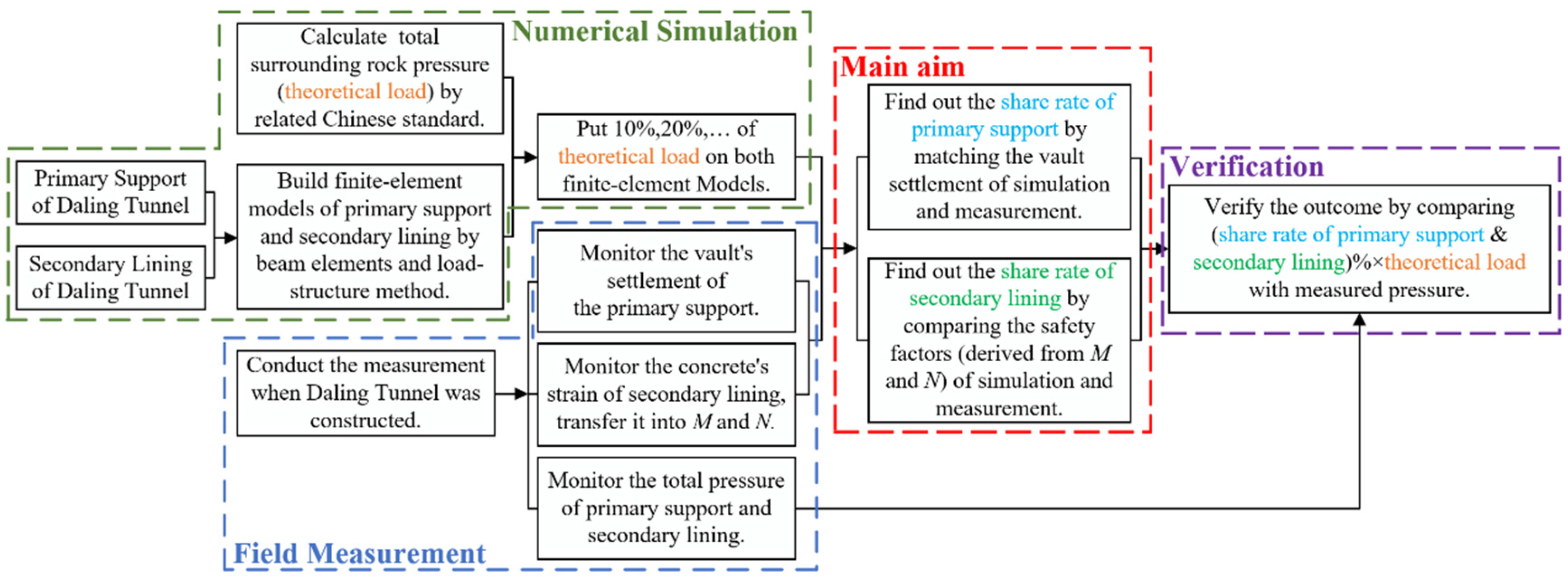
2. Methodology
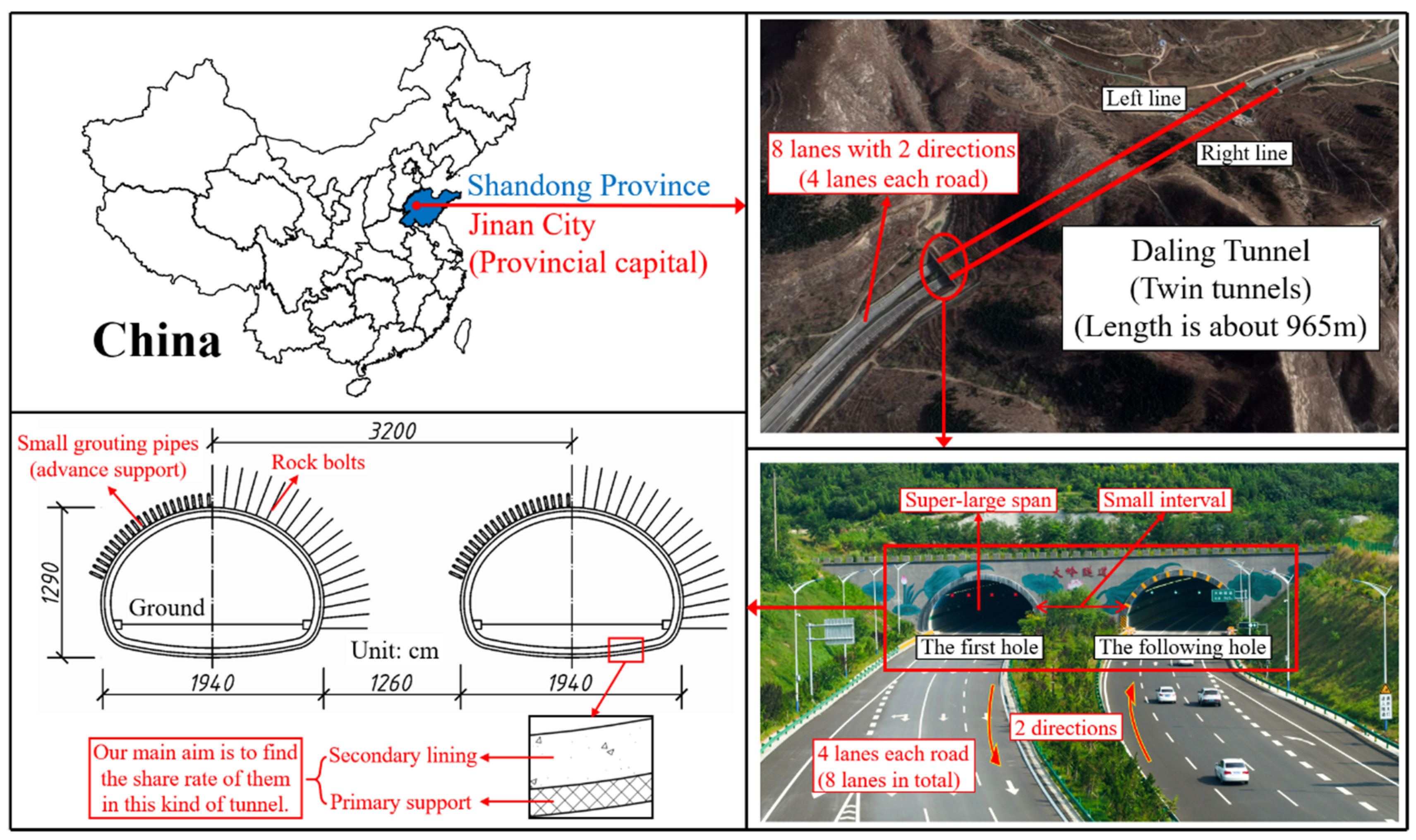
2.1. Daling Tunnel
2.2. Theoretical Load
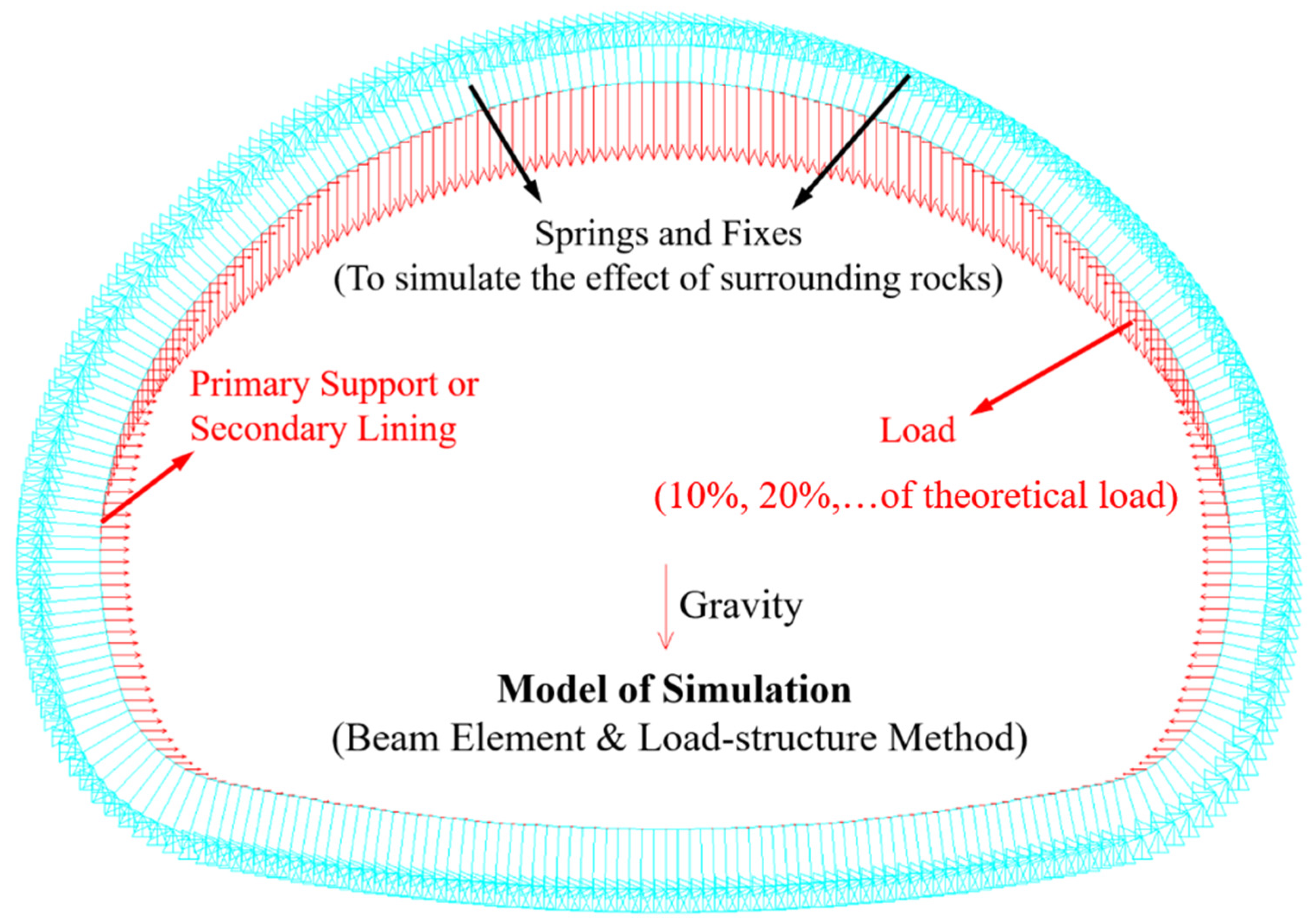
2.3. Finite-Element Model
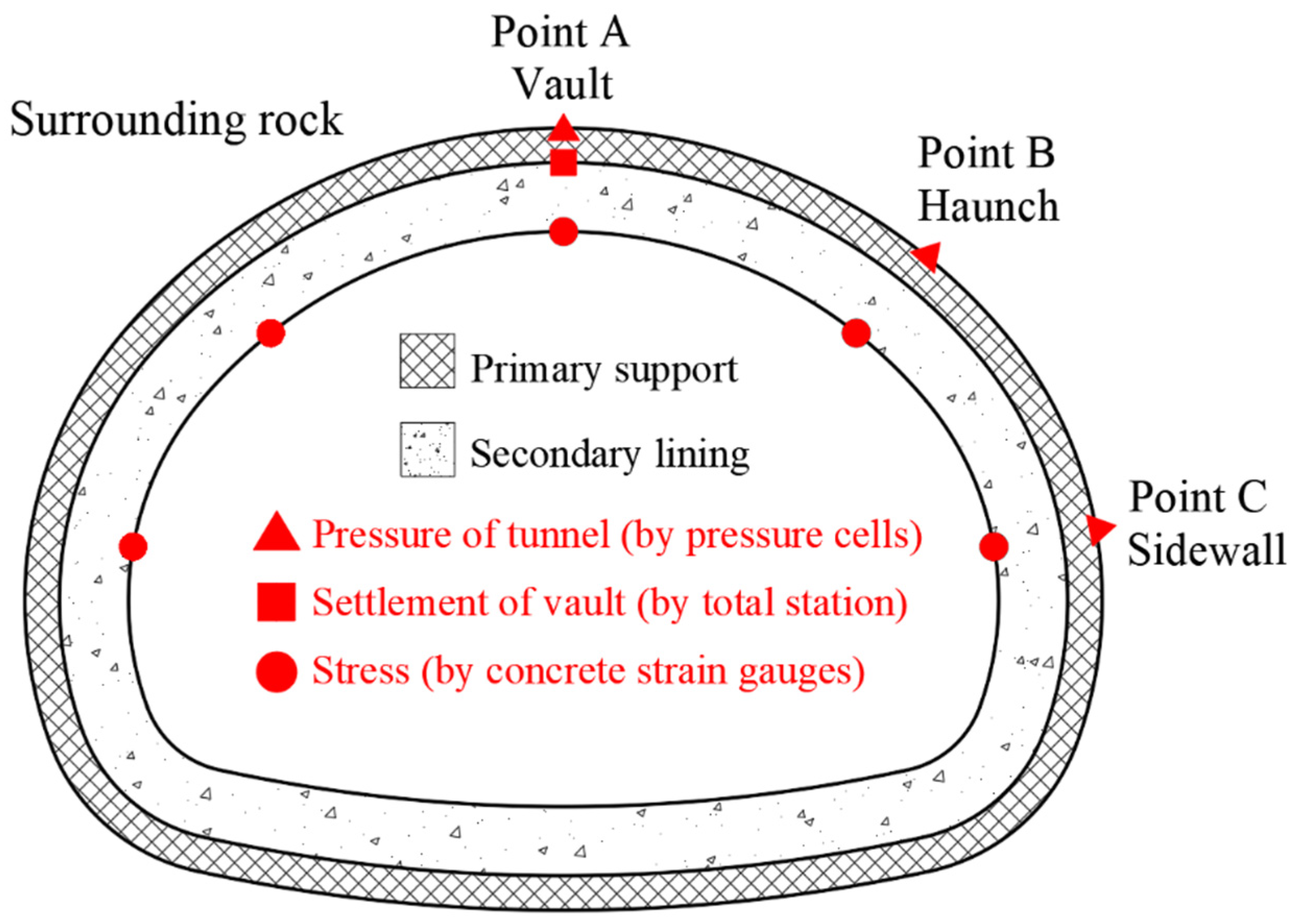
2.4. Field Measurement
- (1)
- Settlement of the vault of primary support was measured by total stations and steel rulers to find out the share rate of primary support.
- (2)
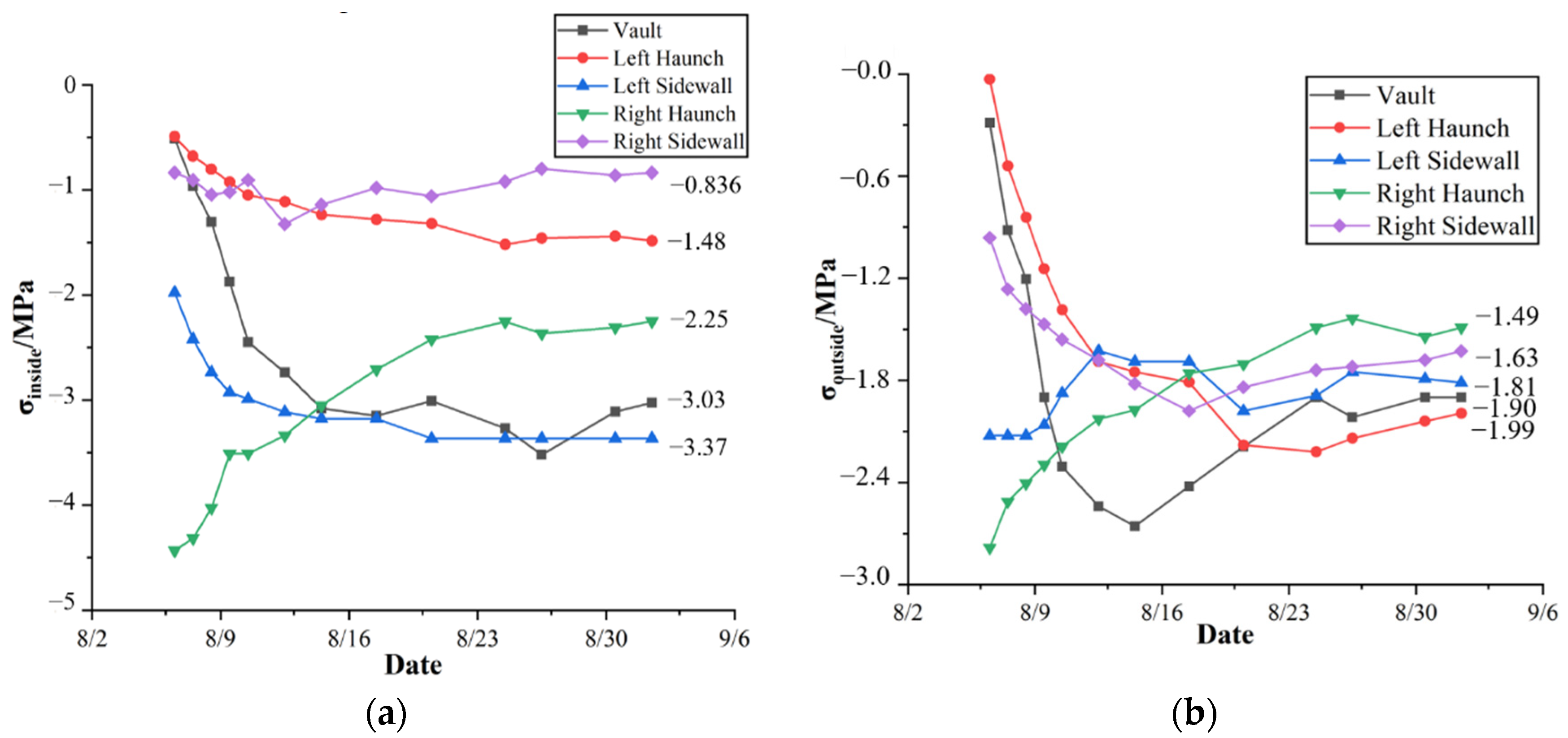
- Stress of the secondary lining (derived from the strain) was measured by concrete strain gauges. The gauges were put on both sides of the secondary lining at each point. This is for finding out the share rate of secondary lining. The arrangement of concrete strains is shown in Figure 6.
- (3)
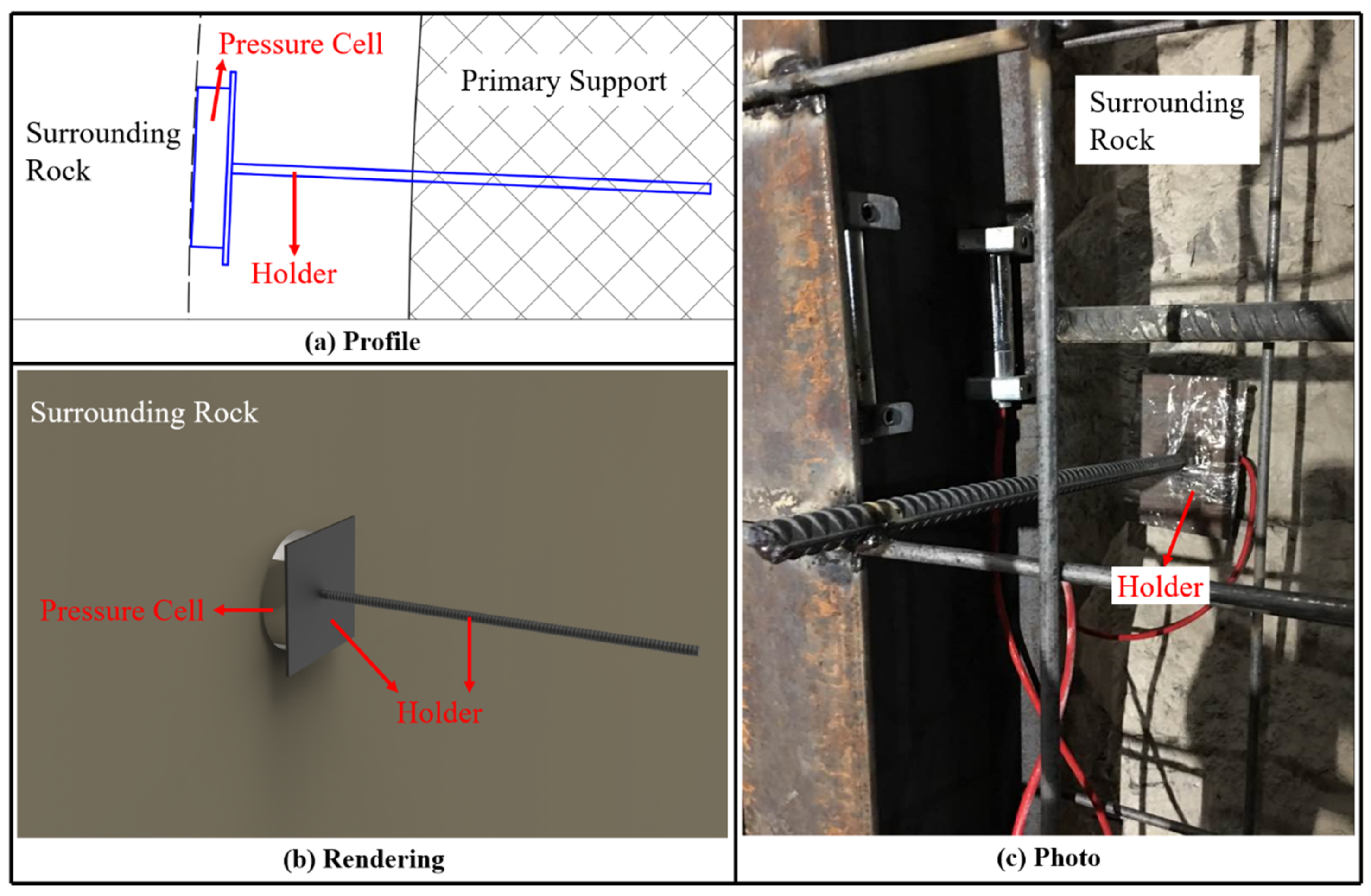
- Total pressure of the primary support and secondary lining was measured by pressure cells arranged at the points A, B, and C at the outside of the primary support. This is for comparison and verification. The arrangement of pressure cells is shown in Figure 7.
3. Theoretical Calculation of Surrounding Rock Pressure
3.1. Failure Mode and Assumptions
- (1)
- Suppose that the ground was horizontal, the rock mass was homogenous, and isotropic and the twin tunnel was symmetry and parallel. Moreover, excavation of left and right holes is sequent and full section.
- (2)
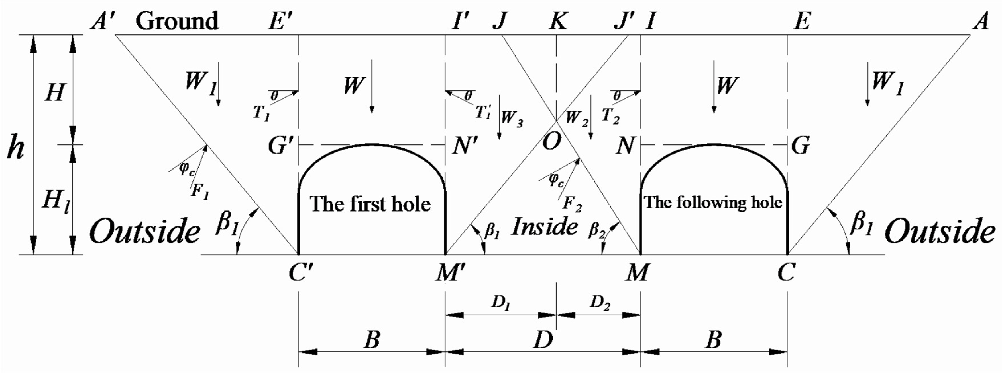
- The excavation of the first hole is similar to an ordinary single-hole tunnel. It means that the fracture planes on both sides of the first hole, which are shown as A’C’ and M’J’ in Figure 8, are two inclined straight planes, and at an angle of to the horizon. In addition, the pressure inside and outside (shown in Figure 8) is symmetric.
- (3)
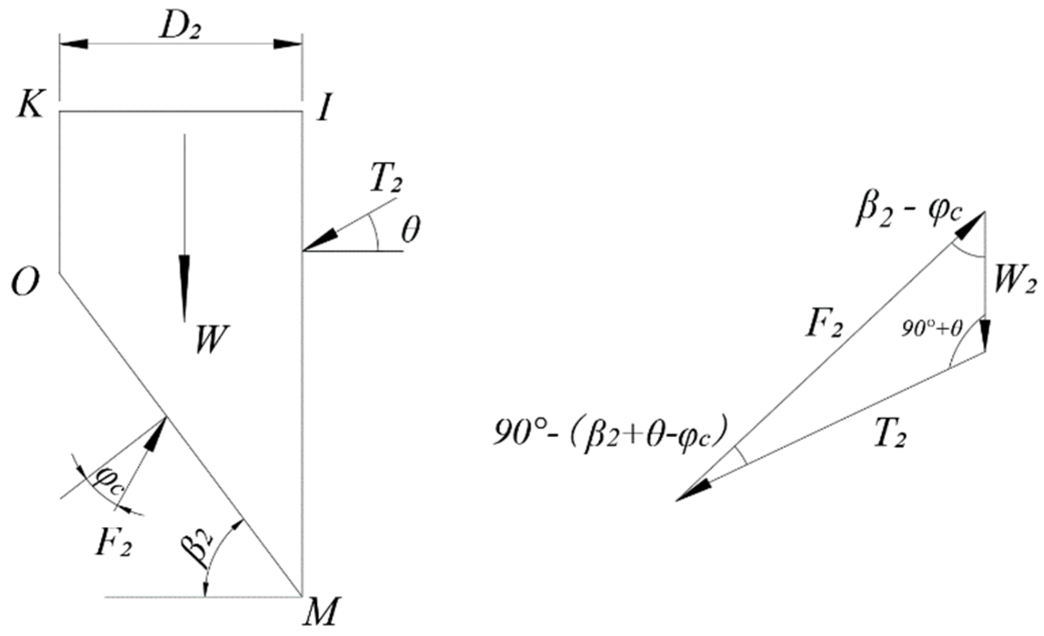
- When the following hole is excavated, the fracture plane at the outside of the hole (AC) is at angle to the horizon, while at the inside of the hole the angle of the fracture plane (MO) is assumed as . Focus on the triangle OJJ’, when the following hole is excavated, it is inclined to slide down along the plane JM. However, since the excavation of the first hole has induced a relative slippage at the plane OJ’ and undermines the cohesion force along the plane OJ’, usually the triangle OJJ’ will not slide and fracture along the plane JO. Instead, the tensile fracture plane will be formed in the triangle OJJ’, which is assumed as a vertical plane (OK). In summary, the fracture plane at the inside of the following hole is assumed as KOM.
- (4)
- According to the sliding trend of the triangle OJJ’ caused by the sequent excavation of the twin tunnel, and based on the theory of soil mechanics, the interactive force (N) in normal direction at the fracture plane OK must be less than the earth pressure at-rest. For safety, let N equal 0.
3.2. Calculation of Theoretical Load
4. Results and Discussion
4.1. Share Rate of the Primary Support
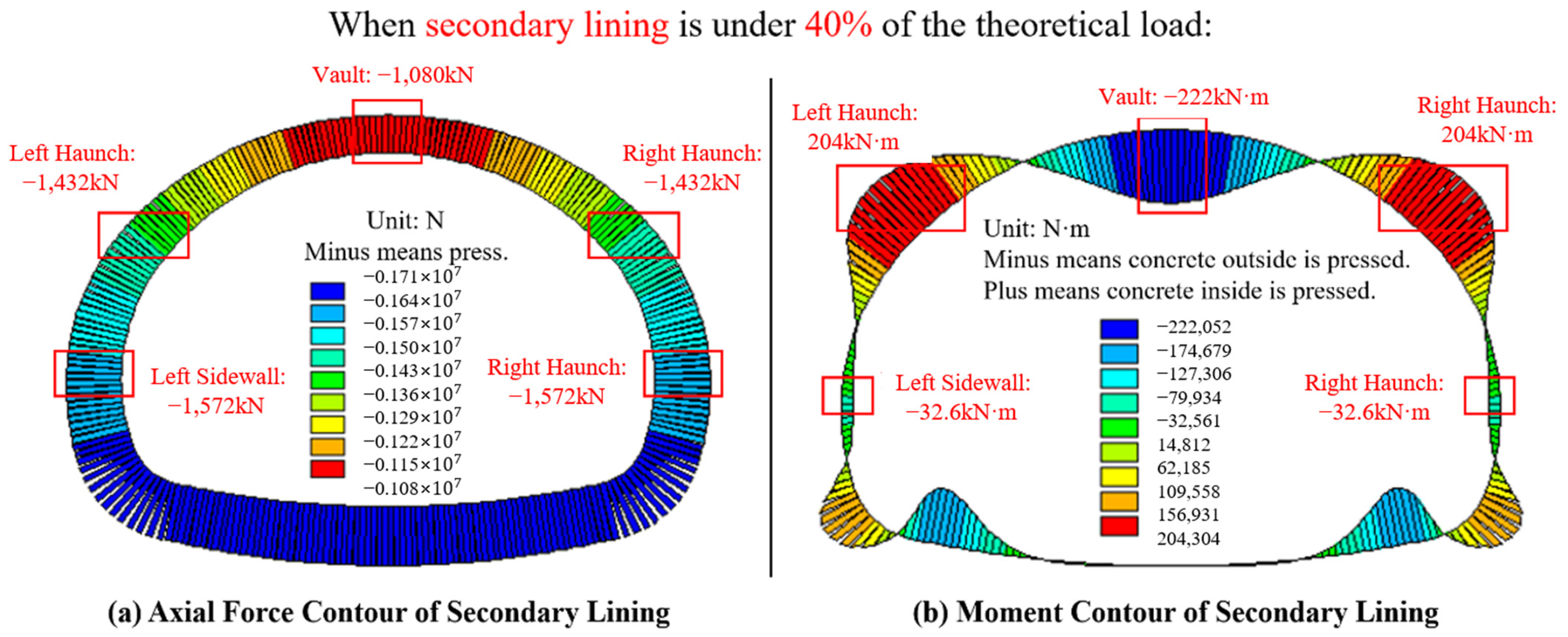
4.2. Share Rate of the Secondary Lining
4.3. Total Pressure for Verification
4.4. Discussion
- (1)
- The influence of the construction’s sequence of the first hole and following hole was not considered in this research, and the way of excavation was assumed as full section excavation.
- (2)
- This paper supposed that the stratum was consistent and the surrounding rock mass was ideal.
- (3)
- The surface of earth was presumed to be horizontal, and so on.
5. Conclusions
- (1)
- The formulas of calculating surrounding rock pressure of normal tunnels (usually including two or three lanes) in Chinese standard could be applied to the super-large span twin tunnels (including four or more lanes). The method was verified by field measurement.
- (2)
- The method of researching the share rate of the primary support and the secondary lining of the tunnel was proposed. The result demonstrates that the share rate of the primary support and the secondary lining of Daling Tunnel are both 40%. Usually for twin tunnels with super-large span in cities, not only the primary support but also the secondary lining should be strong enough to ensure the design is safe and reliable. In addition, this conclusion is conservative when compared to the measurement, which is practical for application in engineering.
- (3)
- The result of the theoretical calculation and numerical simulation was compared with the measurement to evaluate the research methodology and achievements. These two results match properly, which verify the correctness of this study. Hence the conclusions and the method of this research can make some reference to the design, construction, and maintenance of super-large span twin tunnels.
Author Contributions
Funding
Institutional Review Board Statement
Informed Consent Statement
Data Availability Statement
Acknowledgments
Conflicts of Interest
References
- China Railway Eryuan Engineering Group Co., Ltd. Specifications for Design of Highway Tunnels. In Civil Engineering; China Transportation Press: Beijing, China, 2018; JTG 3370.1-2018. [Google Scholar]
- Feng, J.M.; Yan, C.W.; Ye, L.; Ding, X.Q.; Zhang, J.R.; Li, Z.L. Evaluation of installation timing of initial ground support for large-span tunnel in hard rock. Tunn. Undergr. Space Technol. 2019, 93, 103087. [Google Scholar] [CrossRef]
- Hou, F.J.; Li, S.C.; Li, W.J.; Li, X.Z.; Han, X.M. Mechanical Analysis of Large-span Tunnel Construction in Urban Seaside. J. Coast. Res. 2019, 94, 255–259. [Google Scholar] [CrossRef]
- Hou, F.J.; Han, X.M.; Li, S.C.; Li, W.J. Optimization Research of Construction Methods and Parameters of Large-span City Coastal Tunnel in Horizontal Layered Rockmass. J. Coast. Res. 2019, 94, 232–236. [Google Scholar] [CrossRef]
- Li, A.; Zhang, D.L.; Fang, Q.; Luo, J.W.; Cao, L.Q.; Sun, Z.Y. Safety Distance of Shotcrete Subjected to Blasting Vibration in Large-Span High-Speed Railway Tunnels. Shock. Vib. 2019, 2019, 2429713. [Google Scholar] [CrossRef] [Green Version]
- Li, R.; Zhang, D.L.; Fang, Q.; Li, A.; Hong, X.F.; Ma, X.B. Geotechnical monitoring and safety assessment of large-span triple tunnels using drilling and blasting method. J. Vibro Eng. 2019, 21, 1373–1387. [Google Scholar]
- Sun, S.C.; Rong, C.X.; Wang, H.L.; Cui, L.Z.; Shi, X. The Ground Settlement and the Existing Pipeline Response Induced by the Nonsynchronous Construction of a Twin-Tunnel. Adv. Civ. Eng. 2021, 2021, 8815304. [Google Scholar] [CrossRef]
- Liu, C.; Li, S.C.; Zhou, Z.Q.; Li, L.P.; Shi, S.S.; Chen, Y.X. Numerical Analysis of Surrounding Rock Stability in Super-Large Section Tunnel Based on Hydro-Mechanical Coupling Model. Geotech. Geol. Eng. 2019, 37, 1297–1310. [Google Scholar] [CrossRef]
- Chortis, F.; Kavvadas, M. Three-Dimensional Numerical Investigation of the Interaction Between Twin Tunnels. Geotech. Geol. Eng. 2021, 39, 5559–5585. [Google Scholar] [CrossRef]
- Vinod, M.; Khabbaz, H. Comparison of rectangular and circular bored twin tunnels in weak ground. Undergr. Space 2019, 4, 328–339. [Google Scholar] [CrossRef]
- Zhang, D.L.; Chen, L.P.; Fang, Q.; Song, R.G. Research and application on central rock wall dike stability of small interval tunnel. J. Beijing Jiaotong Univ. 2016, 40, 1–11. [Google Scholar]
- Boon, C.W.; Neo, C.W.; Ng, D.C.C.; Ong, V.C.W. Discontinuum analyses of openings constructed with side drift and limited rock cover. J. Zhejiang Univ.-SCIENCE A 2018, 19, 255–265. [Google Scholar] [CrossRef]
- Ghorbani, H.; Ajalloeian, R. A method for selection of optimum distance between twin tunnels under static and pseudo-static conditions, case study: Pooneh tunnel. Geotech. Geol. Eng. 2019, 37, 4435–4446. [Google Scholar] [CrossRef]
- Nematollahi, M.; Molladavoodi, H.; Dias, D. Three-dimensional numerical simulation of the Shiraz subway second line - influence of the segmental joints geometry and of the lagging distance between twin tunnels’ faces. Eur. J. Environ. Civ. Eng. 2020, 24, 1606–1622. [Google Scholar] [CrossRef]
- He, C.; Zhou, S.H.; Di, H.G.; Yang, X.W. Effect of Dynamic Interaction of Two Neighboring Tunnels on Vibrations from Underground Railways in the Saturated Soil. KSCE J. Civ. Eng. 2019, 23, 4651–4661. [Google Scholar] [CrossRef]
- Khabbaz, H.; Gibson, R.; Fatahi, B. Effect of constructing twin tunnels under a building supported by pile foundations in the Sydney central business district. Undergr. Space 2019, 4, 261–276. [Google Scholar] [CrossRef]
- Zhu, J.L.; Zhu, D.Y. Deformation of Pipelines Induced by the Construction of Underlying Twin-Tunnel. Teh. Vjesn.-Tech. Gaz. 2020, 27, 1311–1315. [Google Scholar]
- Yang, Z.H.; Li, S.S.; Yang, D.; Zhou, S.; Zhou, Q. Stability of Twin Shallow Tunnels in Unsaturated Soils Considering Vertical Steady State Flow. Geotech. Geol. Eng. 2019, 37, 4603–4612. [Google Scholar] [CrossRef]
- Golshani, A.; Varnusfaderani, M.G. Innovative design modification during construction of a twin tunnel using real-time field data. Transp. Geotech. 2019, 20, 100254. [Google Scholar] [CrossRef]
- Komu, M.P.; Guney, U.; Kilickaya, T.E.; Gokceoglu, C. Using 3D Numerical Analysis for the Assessment of Tunnel-Landslide Relationship: Bahce-Nurdag Tunnel South of Turkey. Geotech. Geol. Eng. 2020, 38, 1237–1254. [Google Scholar] [CrossRef]
- Bai, B.; Yang, G.C.; Li, T.; Yang, G.S. A thermodynamic constitutive model with temperature effect based on particle rearrangement for geomaterials. Mech. Mater. 2019, 139, 103180. [Google Scholar] [CrossRef]
- Bai, B.; Zhou, R.; Cai, G.Q.; Hu, W.; Yang, G.C. Coupled thermo-hydro-mechanical mechanism in view of the soil particle rearrangement of granular thermodynamics. Comput. Geotech. 2021, 137, 104272. [Google Scholar] [CrossRef]
- Bai, B.; Wang, Y.; Rao, D.Y.; Bai, F. The effective thermal conductivity of unsaturated porous media deduced by pore-scale SPH simulation. Front. Earth Sci. 2022, 10, 943853. [Google Scholar] [CrossRef]
- Sun, K.G.; Hong, Y.Q.; Xu, W.P.; Hou, Z.H.; Liu, X.; Yu, M.Z.; Yuan, Z.Y. Analysis and prediction of mechanical characteristics of corrugated plate as primary support in tunnels. Tunn. Undergr. Space Technol. 2021, 111, 103845. [Google Scholar] [CrossRef]
- Sun, K.G.; Hong, Y.Q.; Xu, W.P.; Liu, H.; Zhen, Y.Z.; Qin, J.H. Analysis and prediction of the mechanical behavior of corrugated plate as primary support in tunnels with elastoplastic constitution. Tunn. Undergr. Space Technol. 2022, 124, 104451. [Google Scholar] [CrossRef]
- Aydin, E.; Dutkiewicz, M.; Öztürk, B.; Sonmez, M. Optimization of elastic spring supports for cantilever beams. Struct. Multidiscip. Optim. 2020, 62, 55–81. [Google Scholar] [CrossRef]
- Wang, Y.H.; Nguyen, N.H.T. The effects of rock-infill interfacial properties on the compressive damage behaviour of flawed rocks: Results from a DEM study. Theor. Appl. Fract. Mech. 2022, 117, 103166. [Google Scholar] [CrossRef]
- Wang, Y.H.; Nguyen, N.H.T.; Zhao, L.H. Micromechanical study on hard rock strainburst using the discrete element method. Tunn. Undergr. Space Technol. 2021, 109, 103793. [Google Scholar] [CrossRef]
- Li, P.F.; Wang, F.; Fan, L.F.; Wang, H.D.; Ma, G.W. Analytical scrutiny of loosening pressure on deep twin-tunnels in rock formations. Tunn. Undergr. Space Technol. 2019, 83, 373–380. [Google Scholar] [CrossRef]
- Guo, Z.H.; Liu, X.R.; Zhu, Z.Y. Elastic Solution for a Deep Twin Tunnel Stress Based on Complex Variable Theory and the Superposition Principle. J. Eng. Res. 2017, 5, 68–86. [Google Scholar]
- Panji, M.; Kavandi, P. Investigating of Effective Parameters on Stress Behavior of Pressure Deep Twin Tunnels under Pressure. Turk Online J. Des. Art Commun. 2016, 6, 1184–1189. [Google Scholar]
- Zhong, Z.L.; Liu, X.R.; Liu, Y.X.; Zhang, J. Theoretical calculation and monitoring on rock pressure of shallow-buried bilateral bias neiborhood tunnel. J. Chongqing Univ. 2013, 36, 63–68. [Google Scholar]
- Lyu, H.M.; Shen, S.L.; Zhou, A.N.; Chen, K.L. Calculation of pressure on the shallow-buried twin-tunnel in layered strata. Tunn. Undergr. Space Technol. 2020, 103, 103465. [Google Scholar] [CrossRef]
- Kong, F.C.; Lu, D.C.; Du, X.L.; Shen, C.P. Elastic analytical solution of shallow tunnel owing to twin tunnelling based on a unified displacement function. Appl. Math. Model. 2019, 68, 422–442. [Google Scholar] [CrossRef]
- Cui, S.S.; Wu, K.; Zhang, Q.J.; Yu, Y.L.; Wang, Y.J. Analysis on Construction Mechanical Mechanism of Highway Tunnels with Large Span and Small Spacing. Geotech. Geol. Eng. 2019, 37, 1627–1642. [Google Scholar] [CrossRef]
- Qiu, J.L.; Liu, H.Q.; Lai, J.X.; Lai, H.P.; Chen, J.X.; Wang, K. Investigating the Long-Term Settlement of a Tunnel Built over Improved Loessial Foundation Soil Using Jet Grouting Technique. J. Perform. Constr. Facil. 2018, 32, 04018066. [Google Scholar] [CrossRef]


| Parameter | Value |
|---|---|
| Unit weight, (kN/m3) | 20 |
| Simplified internal friction angle, | 45° |
| Real internal friction angle, | 22° |
| Friction angle of the sliding plane, | 13.2° () |
| Span, B (m) | 19.4 |
| Height, Hl (m) | 12.9 |
| Net interval, D (m) | 12.6 |
| Buried depth, H (m) | 20 |
| Part | Young’s Model /GPa | Poisson’s Ratio | Unit Weight /kN/m3 | Thickness /m |
|---|---|---|---|---|
| Primary Support | 25.3 | 0.2 | 25 | 0.3 |
| Secondary Lining | 28 | 0.2 | 25 | 0.7 |
| Item | Position | Axis Force /kN | Moment /kN·m | Eccentricity /mm | Attribute | Safety Factor |
|---|---|---|---|---|---|---|
| Simulation | Vault | −1080 | −222 | 493 | All is small eccentricity | 9.47 |
| Left haunch | −1432 | 204 | 430 | 8.19 | ||
| Left sidewall | −1572 | −32.6 | 308 | 10.41 | ||
| Right haunch | −1432 | 204 | 430 | 8.19 | ||
| Right sidewall | −1572 | −32.6 | 308 | 10.41 | ||
| Measurement | Vault | −1723 | −53 | 318 | 7.85 | |
| Left haunch | −1216 | 24 | 307 | 11.54 | ||
| Left sidewall | −781 | 71 | 378 | 14.0 | ||
| Right haunch | −1348 | −36 | 314 | 10.17 | ||
| Right sidewall | −862 | 38 | 332 | 15.00 |
| Measured Point | Theoretical Load /kPa | 80% of the Theoretical Load /kPa | Measured Pressure /kPa | Deviation /% |
|---|---|---|---|---|
| A | 286.90 | 229.56 | 180.94 | 21.18 |
| B | 211.63 | 169.30 | 142.68 | 15.73 |
| C | 98.40 | 78.72 | 65.36 | 16.97 |
Publisher’s Note: MDPI stays neutral with regard to jurisdictional claims in published maps and institutional affiliations. |
© 2022 by the authors. Licensee MDPI, Basel, Switzerland. This article is an open access article distributed under the terms and conditions of the Creative Commons Attribution (CC BY) license (https://creativecommons.org/licenses/by/4.0/).
Share and Cite
Zhao, X.; Sun, K.; Zhen, Y.; Hong, Y.; Zhou, H. Study on Share Rate of Support Structure for Super-Large Span Twin Tunnels with Small Interval. Appl. Sci. 2022, 12, 7498. https://doi.org/10.3390/app12157498
Zhao X, Sun K, Zhen Y, Hong Y, Zhou H. Study on Share Rate of Support Structure for Super-Large Span Twin Tunnels with Small Interval. Applied Sciences. 2022; 12(15):7498. https://doi.org/10.3390/app12157498
Chicago/Turabian StyleZhao, Xuwei, Keguo Sun, Yingzhou Zhen, Yiqin Hong, and Huichao Zhou. 2022. "Study on Share Rate of Support Structure for Super-Large Span Twin Tunnels with Small Interval" Applied Sciences 12, no. 15: 7498. https://doi.org/10.3390/app12157498
APA StyleZhao, X., Sun, K., Zhen, Y., Hong, Y., & Zhou, H. (2022). Study on Share Rate of Support Structure for Super-Large Span Twin Tunnels with Small Interval. Applied Sciences, 12(15), 7498. https://doi.org/10.3390/app12157498