1. Introduction
Rotating cantilever beams are widely used in the engineering field. Related issues in dynamic modeling and analyses have always been the research concern of scholars. Reliable dynamic models for accurate operation and control are necessary. The main concern of the modeling process and method is to provide the description of the dynamic stiffening effect or the so-called geometric stiffening effect.
There are two common modeling methods to deal with rotating cantilever beams. The first kind of method introduces the axial centrifugal force into the dynamic equations of motion directly to provide a positive stiffening effect. It is direct and convenient for dynamics analysis and simulation. Simo et al. [
1] developed this kind of method. Banerjee [
2] used this kind of method to study the effect of hub radius ratios on free vibration. Kaya et al. [
3] analyzed the coupling effect between bending and torsion motions on frequencies. Zhu et al. [
4] derived the equations of flapwise and torsional motion for a rotating beam.
There are also scholars who consider the foreshortening effect to account for the dynamic stiffening. The foreshortening effect relies on the axial shortening caused by bending deformation, leading to the change in axial position. As a result, the stiffening effect of the rotating beam is noticeable. This kind of method based on the foreshortening effect in the axial direction is also widely used. Kane et al. [
5] and Yoo et al. [
6] introduced the deformation variables instead of Cartesian variables to derive the dynamic equations of motions. The foreshortening effect was included in the deformation variable of stretching. Yang et al. [
7] introduced a modeling method called the first-order approximate coupling (FOAC) model that contains the foreshortening effect and von Karman strain theory. The foreshortening term was considered to provide a coupling effect and played a positive role in the stiffness of the chordwise motion. Li et al. [
8] also considered the coupling effect on frequency analysis of a rotating functionally graded material beam. This kind of modeling method was used to perform dynamics analysis of rotating beams by different discrete methods, such as the finite element method [
7,
9,
10], the assumed mode method [
5,
6,
8], and so on.
Among a huge number of modeling methods, the axial deformations of rotating cantilever beams were mentioned and verified. Eventually, the axial deformations were used to capture the dynamic stiffening effect in vibration analysis. Pesheck et al. [
11] derived the equation of flapwise motion by obtaining the axial deformation. By using the expression of axial deformation solution of Pesheck, the free vibration analysis was carried out by Kim et al. [
12]. Another form of the axial deformation solution was provided by Trindade et al. [
13]. Huang et al. [
14] used this form of the axial deformation expression to study the frequencies of the axial, flapwise, and chordwise vibrations. Based on the FOAC model, Zhao et al. [
15,
16] investigated the effect of axial deformation on the bending frequency of rotating cantilever beams.
In particular applications, rotating cantilever beams do not exist alone. Rotating cantilever beams are used to capture or carry something; thus, the dynamic structures are changed accordingly, and the additional mass will have an important influence on the whole system. These structures can be simplified as rotating beams with free end mass to study the dynamics. The two kinds of methods mentioned above are usually used for rotating beams with free end mass. Ansari et al. [
17] analyzed the frequency of a rotating beam with tip mass subjected to torsional-bending vibrations. Song et al. [
18] introduced the model of rotating blades carrying tip mass to study dynamic behaviors. Ahn [
19] studied the random transverse vibrations of a rotating beam with a tip mass. The chordwise frequencies of rotating beams with tip mass were the research focus of Craig [
20], Jones [
21], Yoo et al. [
22], Hoa [
23], and Bhat [
24]. The rotating structures with free end mass were also extended to pre-twisted blades by Yoo et al. [
25], tapered beams by Khulief [
26], composite beams by Tolga et al. [
27], and inclined beams by Lee [
28]. Park et al. [
29] investigated both the responses and frequencies of rotating curved beams with tip mass. Yang et al. [
30] and Cai et al. [
31] applied the FOAC model to carry out the dynamics analysis of a flexible hub-beam system with a tip mass under large motion. The effects of damping and external forces were discussed. Kuo et al. [
32] investigated the dynamic stability and vibration control.
However, in the methods mentioned above, several aspects are simplified in the modeling process: (1) while dealing with the normal strain, incomplete consideration of geometrical nonlinearities of the rotating cantilever beams is involved, and the nonlinear term in the axial direction is usually ignored; (2) the axial deformation has not been considered in the analysis of rotating cantilever beams with free end mass. Meanwhile, the axial deformation is only considered for chordwise vibration analysis, but not for axial vibration analysis. In order to resolve the problems mentioned above, this study proposes an improved dynamic method for rotating cantilever beams with free end mass. The dynamic stiffening terms are not added in advance, and the dynamic behaviors are performed by real-time deformation. In the meantime, the axial deformation is introduced into the vibration analysis. Numerical simulations are performed to validate the proposed model for the dynamic stiffening effect, and the results are compared and discussed with the other previous modeling methods. The comparisons show that even a small free end mass has an important influence on the dynamic characteristics of rotating beams. Furthermore, the influences of various parameters on the vibration frequencies of rotating cantilever beams are investigated, such as angular speed, free end mass ratio to beam’s mass, and center body radius ratio to beam length.
2. Equations of Motions
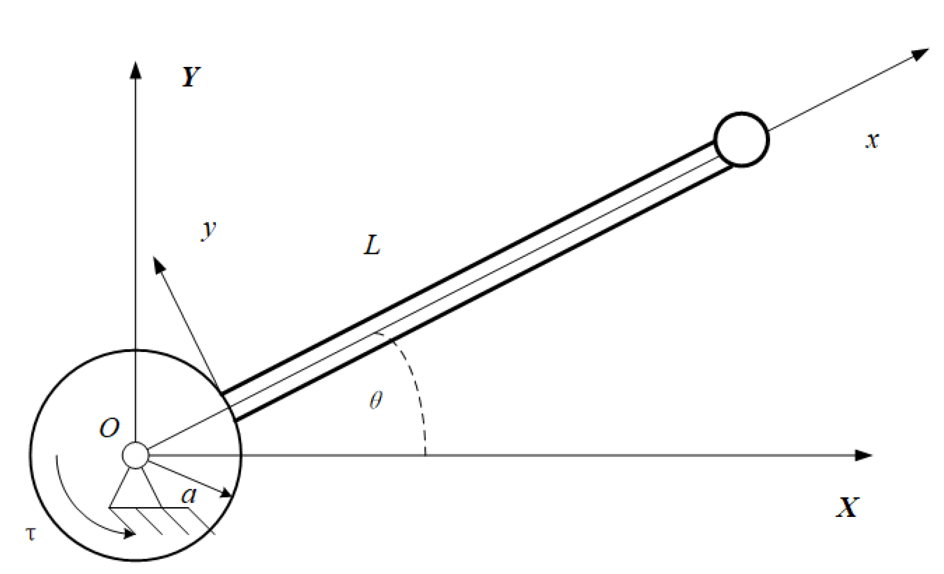
As shown in
Figure 1, the object in this study is the rotating cantilever beam system with a free end mass. A rigid center body, which rotates around the fixed axis
O with angular speed
, has the radius
a. There is a rotating cantilever beam mounted on the edge of the rigid body, with the density
, the elastic modulus
E, the length
L, the cross-sectional area
A, and the section moment of inertia
I. A lumped mass
m is attached at the beam’s free end. Before the cantilever beam is deformed, the neutral axis extension line passes through the rotation axis
O. The inertial coordinate system
is established through the fixed axis
O of the rigid center body, and the floating coordinate
is established at the connection point
o.
is the external moment act on the center body, and
is the angle of the cantilever beam departure from the inertial system.
Here, we treat the cantilever beam as a Euler–Bernoulli beam in order to neglect the torsional and shear deformations. This simplification makes our model more tractable. Thus, we can use the displacements at the neutral line to represent the displacements of an arbitrary point in the cantilever beam. The displacements of the arbitrary point
P in the
x and
y direction are
u and
w in the floating coordinate system
, respectively. Then, the vector
of the point
P in the cantilever beam after deformation and the vector
of the free end mass
m are given as:
where
is the rotational transformation matrix,
is the vector of the origin o,
and
are the vectors of the point
P and the free end mass
m in the floating coordinate system
, which are given as:
The corresponding velocities of the point
P and the free end mass
m are given as:
where a top dot means the derivation with respect to time
t. The details of
and
are shown as Equations (A1) and (A2) in
Appendix A.
Thus, the kinetic energy
T is given as:
According to continuum mechanics, a fully normal strain–displacement relationship should be expressed as:
It is also called the Green strain theory. In previous studies, it is usually reduced to a simplified form called the von Karman strain theory. The difference between the Green strain theory and von-Karman strain theory is that the axial nonlinear term
is not included in the von Karman strain theory. This term contains the effect of axial geometric nonlinearity. With the consideration of the cantilever beam’s complete geometrical nonlinearity, the Green strain theory is used instead of the von Karman strain theory in this study. Thus, our analysis, which takes into account the additional term, seems more practical, particularly since the rotating beam is subjected to axial centrifugal force.
It is illustrated in some studies [
12,
33] that the calculation results of linear stress combined with nonlinear strain agree with the results of nonlinear stress combined with nonlinear strain. The discrepancies are minor and within acceptable ranges. So, the corresponding stress can be given as:
Thus, the potential
H of the cantilever beam includes tensile deformation energy and bending deformation energy will be given by:
Substituting the expression of kinetic energy
T and potential energy
H into the following Hamilton’s principle:
the dynamic equations describe the in-plane axial and chordwise motions of the rotating cantilever beam system with free end mass can be described as:
In the case of uniform rotational motion, the system is in an equilibrium state. According to the perturbation principle, the deformations of a cantilever beam can be regarded as the sum of the deformations in the equilibrium state (or the equilibrium deformations) and the perturbed deformations:
where
and
are the equilibrium deformations, while
and
corresponded to the perturbed deformations, respectively. In the meantime, the equilibrium deformations
and
should be fixed values in the equilibrium state. The derivatives of
and
with respect to time are zero.
The perturbed deformations mean the vibration deformations of a rotating cantilever beam, are in the neighborhood of the equilibrium deformations. Hence, it is necessary to obtain the equilibrium deformations. According to the static equilibrium state, the equilibrium equations are obtained as:
Here, it can be seen that the lumped mass at the free end will cause additional axial deformation due to rotation.
Hence, the analytical solution of the equilibrium axial deformation is obtained as:
Correspondingly, the axial strain according to the equilibrium axial deformation is obtained as:
Pulling off the equilibrium deformations from the dynamic equations of motion, the linearized equations to describe the free vibration in the equilibrium state are derived as:
for simplicity,
can be omitted from
and
in the equations of vibrations. The underlined terms in Equations (17) and (18) contain the equilibrium axial deformation induced by rotational motion, including the influence of the beam itself and the free end mass. In previous models, it needs an extra independent term corresponding to the free end mass to provide a positive effect to the chordwise vibration. However, here in this study, the influence of rotational motion is provided by the beam’s equilibrium deformation. Meanwhile, Equations (17) and (18) show that equilibrium axial deformation affects not only the chordwise vibration but also the axial vibration. The effect of equilibrium axial deformation on dynamics will be discussed in the later section.
Applying the Galerkin method to derive the discretized equations of motion. Here, we denote the weighting functions of the axial and chordwise deformations as
and
. Multiplying Equations (11) and (12) by
and
, the following variational equations of rotating motions are represented by:
The trial functions represented the approximate solutions for the axial and chordwise deformations are combined as the linear basis functions and generalized coordinate functions. Thus, the trial functions can be expressed as:
where
N is the number of linear basis functions,
and
are unknown time-related generalized coordinate functions, and
and
are the basis functions. In this study, the mode functions for the axial and chordwise motions of a cantilever beam are selected as the basis functions. Those are:
where
is the
i th root of the following equation:
Similarly, the same series of basis functions are applied to the weighting functions of the axial, chordwise motions:
where
and
are unknown time-related generalized coordinate functions.
Substituting the above trial functions into Equations (19) and (20), it leads to the discretized equations of motions in matrix form as follows:
where
It can be seen that the underlined terms in Equations (32) and (33) are related to the real-time generalized coordinates of the rotating cantilever beam. Without these underlined terms, Equations (26) and (27) will degenerate into the dynamic equations without stiffening effect. The role of these underlined terms will be discussed in the next section.
Then, the discretized equations of free vibrations can be obtained as:
where
The axial and chordwise vibration frequencies can be calculated by calculating the characteristic equations that need the determinant of the characteristic equation matrix equal to zero, in which means the frequency of free vibration motion. To solve the eigenvalue problem, we wrote the program in C++ and solved it using the QR algorithm.
3. Dynamics Simulations
In order to validate the proposed model, the dynamic responses of the rotating cantilever beam with free end mass are simulated in this section, and comparisons of the results are presented with other published works. The example is selected as cases considered in Refs. [
31,
34]. The parameters of the system are listed as follows. The beam length is
m, the cross-section area is
m
, the area rotary inertia is
m
, the mass density is
kg/m
, and the modulus of elasticity is
Pa. The lumped mass attached at the free end of the cantilever beam has the parameter
kg.
The law of angular speed of the rotating cantilever beam system described in Refs. [
31,
34] is:
in which
s, and the simulation time is set as 20 s. The different values
for the simulations are selected to be 0.6, 2, and 4 rad/s.
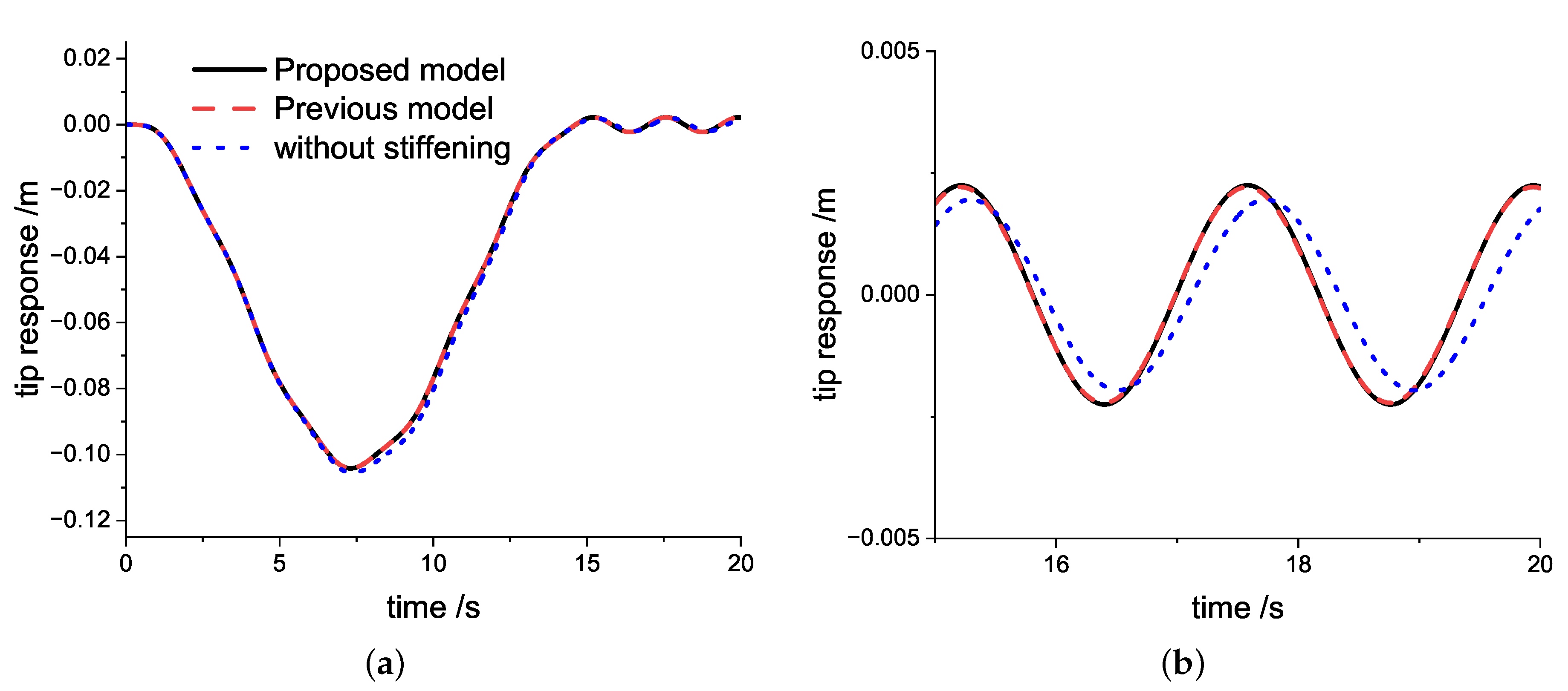
When
is set to be 0.6 rad/s, the response of the beam’s free end when using the proposed model, the previous model from Cai et al. [
31], and the model without stiffening effect are presented in
Figure 2. As shown in
Figure 2a, since the rotating angular speed is low in this case, all three models can calculate the dynamic responses. The results of the response time history curves are similar, curves in the proposed model and the previous model fit well, and the model without a stiffening effect already exhibits a slight difference.
Figure 2b is a larger image of
Figure 2a for the time 15 s
20 s. It is observed that the vibration responses of the proposed model and the previous model are almost coincident, but the vibration of the model without the stiffening effect has a larger cycle.
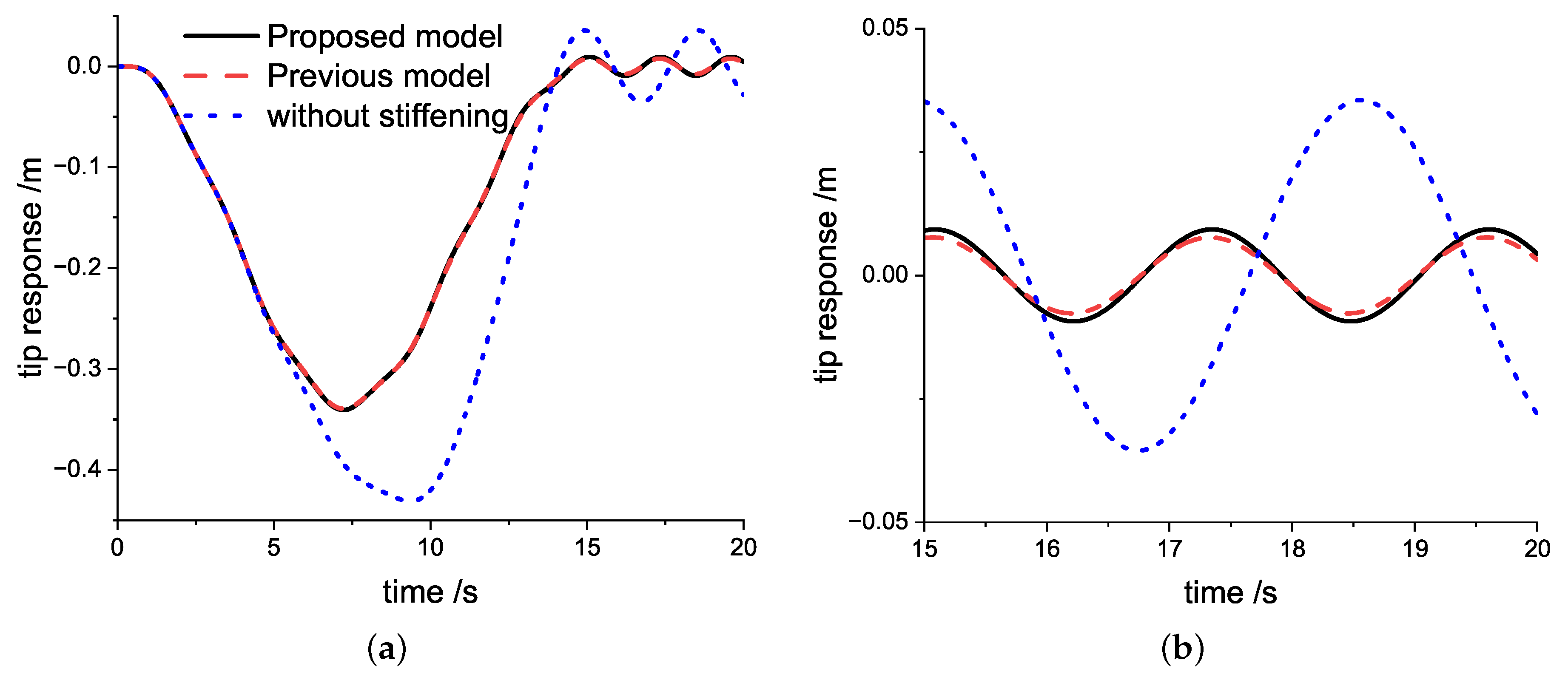
Considering the case when
rad/s in
Figure 3. The response time history curves in the first two models are still similar and stable. It only shows a slight difference in the uniform rotating stage. However, the response at the free end, which is calculated by the model without stiffening effect, shows a considerable difference compared to the others. The model without stiffening has a larger free end response in the acceleration stage, and the calculation result gives an even larger amplitude and vibration cycle at the uniform rotating stage. A larger vibration cycle means a smaller frequency. In the model without stiffening, the dynamic softening phenomenon occurs.
A larger angular speed case is simulated where
rad/s. It can be observed in
Figure 4 that the result of the model without the stiffening effect is divergence. The model with the stiffening effect is unable to obtain an effective result. The proposed model in this study can still simulate the dynamic response of a rotating beam with free end mass at high speed condition as the previous model does. It proves that although no additional stiffening term is introduced in the process of deduction, the proposed model is an effective dynamic stiffening model by accounting for real-time deformation coordinates. The underlined terms in Equations (26) and (27) can provide the dynamic stiffening effect. Meanwhile, the proposed model exhibits larger vibration amplitudes in the uniform rotating stage compared to the previous model. It should be noted that the stiffness terms in the previous model are constant (time-independent) at this stage, but they are time-variant terms in the proposed model. These are the reasons for the differences between the models.
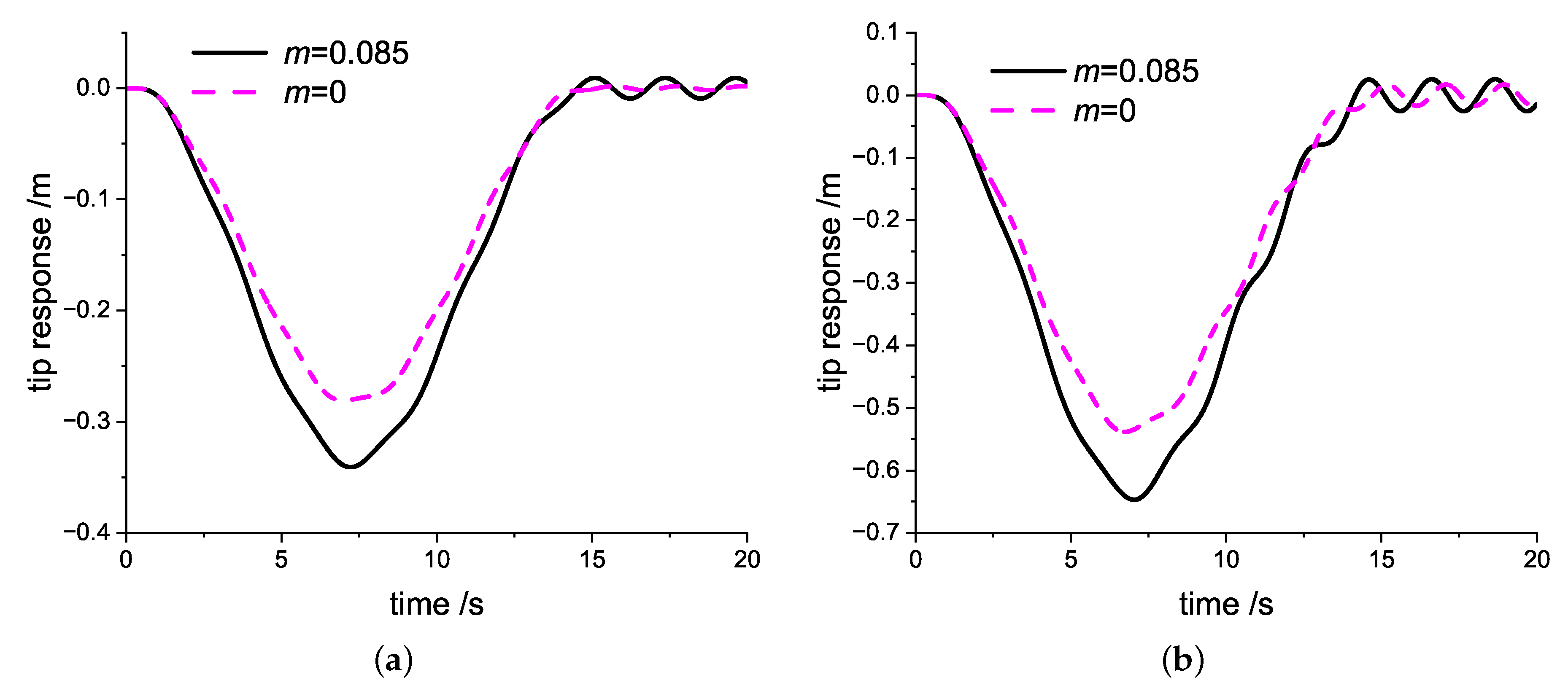
Figure 5 shows the responses of rotating cantilever beams for different free end masses calculated by the proposed model. For the same angular speed parameters, it can be seen that the free end mass results in larger deformation values during the movement. It also brings a larger vibration amplitude in the stage of uniform rotation. In addition, the observations show that the vibration cycle of the rotating beam with free end mass is larger than the beam without free end mass, which means that the free end mass reduces the vibration frequency under the same condition.
4. Frequency of Free Vibration
For analysis and comparison of normalization, several dimensionless parameters are introduced as follows:
where
is the center body radius ratio,
is the slenderness ratio of the beam,
is the mass ratio of the free end mass,
is the dimensionless rotating angular speed,
f is the dimensionless frequency, and
is the natural frequency.
First, to validate the proposed model, the convergence characteristics of the frequency of the free vibration are studied. Considering the case when
,
,
, and
, the first five-order dimensionless frequencies of axial and chordwise vibrations are listed in
Table 1 and
Table 2, respectively. It can be seen that the first five-order dimensionless frequencies converge as the basis function number
N increases. The chordwise vibration frequencies converge faster than the axial vibration frequencies, and the low-order frequencies converge faster than the high-order frequencies. Reliable converged results can be calculated when
N = 20, as shown in
Table 1 and
Table 2. Thus, the number of basis functions will be selected as 20 for further computations in this study.
The effect of the increasing dimensionless angular speed on the free vibration frequencies of the rotating cantilever beam with free end mass is compared between the proposed model and those from previous models when
,
, and
. The models used for comparison are the proposed model, the previous model from Cai et al. [
31], and the model without stiffening effect.
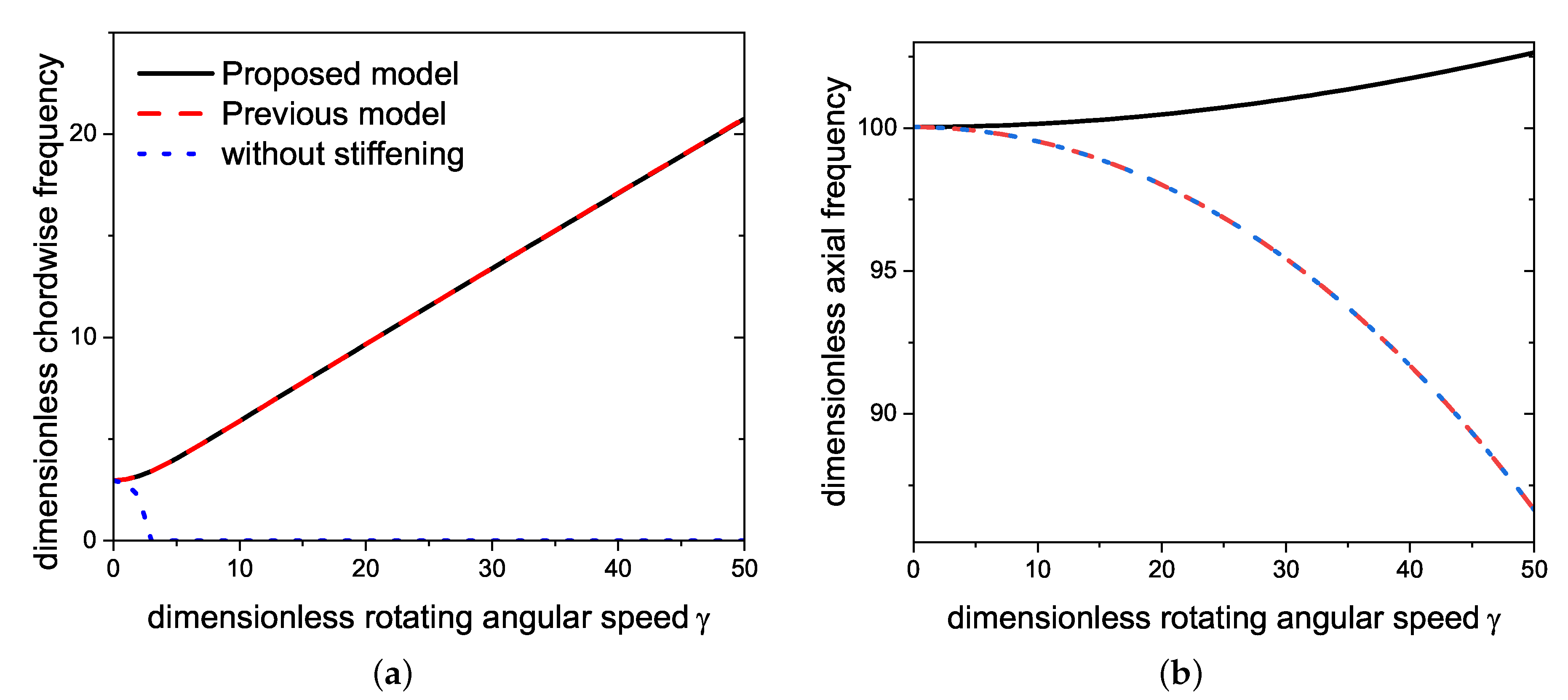
Figure 6 presents the dimensionless first-order frequencies of chordwise and axial free vibration. As shown in
Figure 6a, the first order frequencies of chordwise vibration from the proposed and previous models are almost overlapped. The frequencies increase with the increasing dimensionless rotating angular speed
. However, the frequency of the model without stiffening decreases with the increasing dimensionless speed
. The phenomenon in which the frequencies increase with the angular speed is called the dynamic stiffening effect. The proposed model is an effective model for exhibiting the dynamic stiffening effect as the same as the previous model in chordwise vibration. Generally, the influence of rotating motion on chordwise motion is the primary focus of different modeling methods, but it is still necessary to investigate the influence on the axial motion. A pretty different result is exhibited in
Figure 6b; that is, the axial vibration frequency of the proposed model increases with angular speed
, but the other two models decrease. The previous model shows the same rule of the axial vibration frequency as the model without stiffening. The difference means that the proposed model is dynamic stiffening in axial vibration, but the other models are dynamic softening. From the underlined terms in Equations (16) and (17), the reason is that the influence of equilibrium axial deformation is considered in axial motion in the proposed model, but those are not the consideration in the other models.
Figure 7 shows the variation in different free end mass ratios on the vibration frequencies when
,
, and the variable parameter mass ratio
= 0, 0.3, and 0.5, respectively. It can be observed in
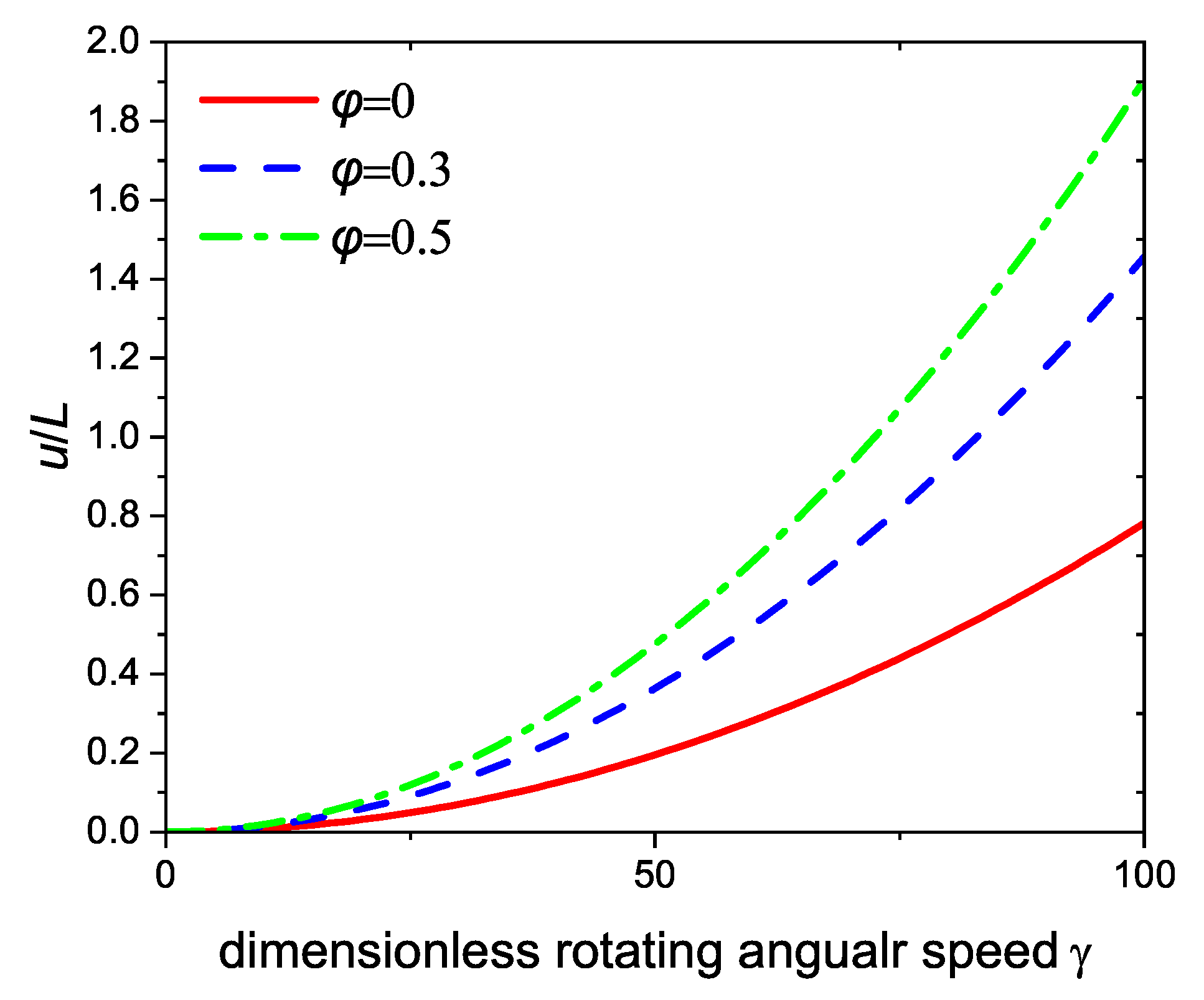
Figure 7a,b that the attached lumped mass makes the fundamental frequencies of the no-rotation cantilever beam decrease both in chordwise and axial vibration. As the dimensionless rotating angular speed increases, the first three frequencies increase. Different-order frequencies have different sensitivities to free end mass and angular speed. As shown in
Figure 8, it is the magnification of
Figure 7. The first order frequencies with free end mass are always smaller than those without free end mass. A bigger free end mass leads to a smaller first frequency at the same speed, consistent with the response results observed in
Figure 5. However, it shows differences in high-order frequencies. As shown in
Figure 8a, the second-order frequencies with free end mass are smaller than those without free end mass in low angular speed range, but those with free end mass will transcend the frequencies without free end mass as the dimensionless angular speed continues increasing. The value of dimensionless angular speed where the transcendence occurs can be called the overtaking speed. In the comparison of the same order frequency, it is observed that a bigger free end mass corresponds to a smaller overtaking speed. Meanwhile, the overtaking speed of high-order frequencies is greater than the lower orders under the same free end mass. The same rules occur in axial motion, as presented in
Figure 8b. In the previous model shown in
Figure 9, although the chordwise frequencies show the same rule as the proposed model, the frequencies of axial motion exhibit differences. The high-order frequencies with free end mass are always smaller than those without free end mass. The performance of chordwise and axial motions for different free mass ratios is consistent in the proposed model, but it is not consistent in the previous model. The slope of each order of dimensionless frequency curve increases with the value of the free end mass ratio. The free end mass has more significant influence on high-order frequencies than on low-order frequencies. The increasing free end mass can strengthen the dynamic stiffening effect of the high-order frequencies.
Figure 10 is the corresponding variation of free end axial deformation to beam length. It shows that a bigger free end mass will result in a greater axial deformation. The effects of different free end mass ratios on frequencies and axial deformations are consistent and more significant in the high speed range.
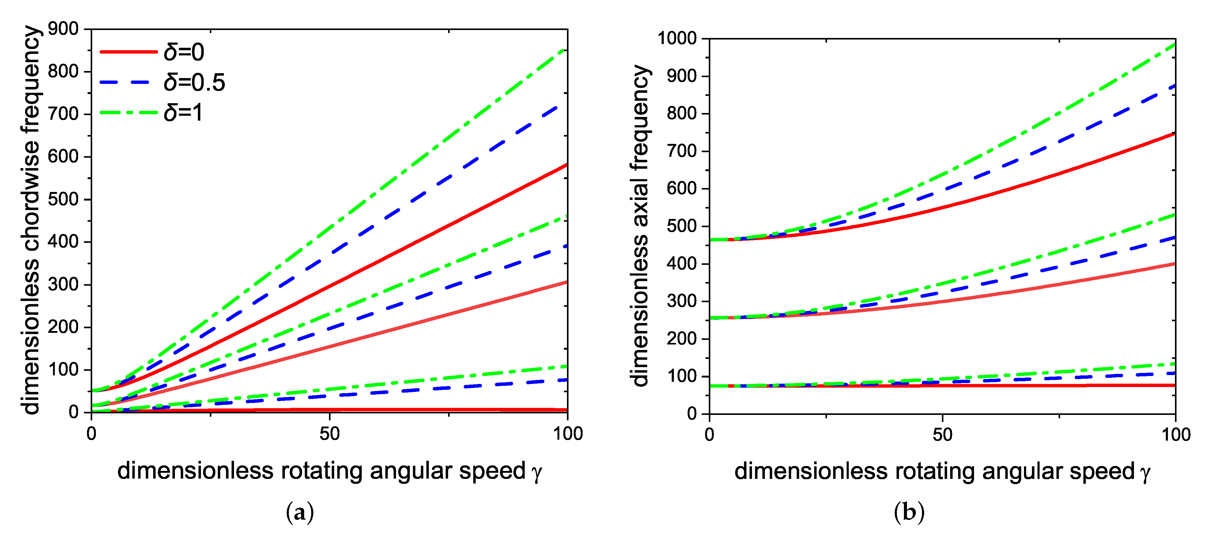
Figure 11 shows the variation in different center body radius ratios on the vibration frequencies when
and
, and
Figure 12 shows the corresponding variation of the free end axial deformation to beam length. It is observed in
Figure 11a,b that a bigger center body radius ratio leads to a bigger dimensionless frequency at the same speed. The slopes of different-order dimensionless frequency curves increase as the center body radius ratio increases. The increasing center body radius ratio can strengthen the dynamic stiffening effect.
Figure 12 demonstrates that the ratio of axial deformation to beam length becomes more prominent as the center body radius ratio becomes larger. The effects of different center body radius ratios on frequencies and axial deformations are consistent, and the influences are more significant in the high-speed range.


