Article

Study on Reducing Towing Drag by Varying the Shape and Arrangement of Floats and Gears

1
Institute of Low-Carbon Marine Production Technology, Pukyong National University, Busan 48513, Korea
2
Organization for Marine Science and Technology, Nagasaki University, Nagasaki 852-8521, Japan
3
Division of Marine Production System Management, Pukyong National University, Busan 48513, Korea
*
Author to whom correspondence should be addressed.
Appl. Sci. 2022, 12(15), 7606; https://doi.org/10.3390/app12157606
Submission received: 1 July 2022 / Revised: 21 July 2022 / Accepted: 26 July 2022 / Published: 28 July 2022

Abstract

:
Many studies have been conducted with the aim of reducing fuel consumption by the fishing industry. We examined whether drag can be reduced by changing the arrangement of gears without requiring the development of new parts for the conventional float and ground gear. Ten differently shaped floats and ground gears were measured in a water flume tank. The float and ground gear were fixed to a steel rod to measure fluid drag according to attack angle, using a multi-component load cell. To estimate the frictional drag of ground gear on the seabed, five types of large ground gear were towed on flat land while changing attack angle using the load cell to measure tension. The fluid drag of the float and ground gear was highest at an attack angle of 60°, regardless of shape, size, and flow velocity. The resistance coefficients of the float and ground gear varied depending on the attack angle and tended to be lower at small attack angles. The frictional drag of the ground gear was greater when the axis of rotation had a small attack angle in the towing direction compared to other attack angles. We then investigated a method for designing bottom-towed gear that reduces drag while maintaining the size, buoyancy, and sinking force of conventional fishing gear parts. This gear design showed 1.2% drag reduction and an estimated 0.8% improvement in fuel efficiency per haul.

1. Introduction

Fishing with towed gear is a popular fish-catching method worldwide. The bag-shaped net can be towed through the surface, middle, and bottom layers of the sea. Because of its flexibility, this gear can be used on many types of fishing grounds by both small and large vessels for a wide range of target species [1]. This fishing method provides a valuable food source for humans, however, it is one of the most energy-intensive food-production methods [2]. Fishing with towed gear depends heavily on internal combustion engines powered by oil fuels.
Fuel costs in the fishing industry have risen substantially over the last 40 years, owing to three major oil price spikes. The rapid increase in fuel costs in recent years has severely affected the profitability of many fisheries. Additionally, the medium-term forecasts for oil prices indicate a high likelihood for further and steady increases [1,3]. Consequently, the increase in operational costs resulting from high oil prices in the past few years have become a serious concern for the fishing industry [4].
The rise in fuel costs, labor shortages, and increases in other costs have caused a decline in the use of towed gear by fisheries [5]. Since the 1980s, problems such as the decline of fishery resources, strict regulation of international fisheries, and competition have continued to threaten fishery management in this industry [5].
Fishing with towed gear is increasing worldwide, more than other methods, and is responsible for approximately 40% of worldwide production [6]. However, in East Asia, due to limited resources and competition between Korea, Japan, and China, statistics show that the production of fishing with towed gear in Korea and Japan has been decreasing [7,8].
To reverse this decline in the pair trawl fishery, a deficit reduction in fishery management is necessary. There are several ways to reduce this deficit, such as increasing the benefits of fishing and/or reducing expenditure. All operational expenses, such as fuel and labor, have risen substantially [5]. Fuel expenditure has accounted for 10–20% of total expenditure since 2005 [5]. Therefore, it is necessary to eliminate the deficit by reducing fuel costs. Research and development on various energy-saving technologies in fisheries have been promoted to reduce fuel costs [1,9,10,11,12], but fuel costs continue to account for the majority of fishery expenditures.
Many efforts have been made to reduce fishing’s fuel consumption with towed gear, such as using fuel additives to improve the burning efficiency of engines and changing the vessel engine for improved fuel consumption efficiency [5]. However, these efforts were not continued because they imposed a heavy burden on fishermen. In practice, using fuel additives and replacing vessel engines incurred high costs for the fishermen.
Therefore, one way to mitigate this issue for towed fishing gear is to reduce gear drag. It has been reported that low gear drag consumes less fuel than does existing gear [1,11]. Several ways to reduce drag have been proposed. Decreasing the towing speed with a low engine speed using a suitable nozzle and propeller [13] is one suggestion. An appropriate nozzle and propeller could result in fuel savings of 20%. A slight reduction in cruising speed to and from the fishing ground reduces fuel consumption [14]. However, with decreased towing speed, the catch of the target fish may also decrease. Another option is to use modern design trawl doors and nets to reduce drag. A large portion of drag in a towed bottom trawl is due to the resistance of the trawl doors required to spread the trawl [14]. The modern design of trawl doors reduces this resistance, and the use of thinner and stronger twine and an increase in net mesh size can also result in substantial fuel savings [14].
Based on these previous mitigation options, a different idea for reducing gear drag, which would be a smaller burden and a more realistic option for fishermen, was designed; combining appropriate netting, floats, and ground gear from conventional gear setups to decrease drag. This method is easier to implement than previous methods that attempted to reduce the total costs of fisheries using towed nets, while minimizing impacts and energy consumption.
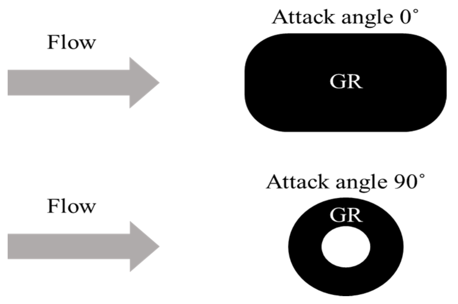
In this study, we propose a design for fishing gear (low-drag gear) in which appropriate parts are placed on the gear. We prepared floats and ground gear that are typically used in the pair trawl fishery and conducted a series of flume tank experiments to understand the hydraulic drag force of conventional floats and ground gear. Additionally, different attack angles were also measured in the flume tank experiment. The frictional drag of ground gear was measured on dirt ground that had a similar terrain to the sea bottom. We present the results of drag measurements for floats and ground gear commonly used in trawl fisheries and discuss possible methods to reduce gear drag.

2. Materials and Methods

2.1. Flume Tank Experiment for Hydraulic Drag

The experiments were conducted in a flume tank. The flume tank generates laminar flow ranging from 0 to 1.2 m/s in the observation section (L × W × D: 6 × 2 × 1.2 m) of the tank. The distribution of side currents is constant, and experiments were conducted within that range. A multi-component load cell (NISSHO LMC-3520-5, capacity 49 N, accuracy ± 0.5% of value) at the side of the bridge was set on the observation area. The drag was measured at intervals of 100 Hz in the experiment.
Various types of floats and ground gear are generally used for the head rope and ground rope of the towed gear in order to maintain the vertical opening of the net, and to protect it from contact with the seabed. Ten floats and ten ground gear types, which are typically used in trawl fisheries, were prepared. There were five ellipsoid-shaped (F1–F5) and five sphere-shaped floats (F6–F10). There were two ellipsoid-shaped (G1–G2), seven cylindrical (G3–G9), and one sphere-shaped (G10) ground gear. Each float and ground gear was of a different size, buoyancy, sinking force, and material (Table 1). A hole was made in each float and ground gear, and an iron bar was inserted into the hole. The end of the iron bar was set in a multi-component load cell. The hydraulic drag of the floats and ground gears were measured at attack angles of 0°, 30°, 60°, and 90°, and the flow speeds were set to 0.5 m/s, 0.75 m/s, and 1.0 m/s. The attack angles are shown in Figure 1. Each drag force was measured at a sampling rate of 100 Hz for 2 min and recorded on a personal computer. The drag of the float or ground gear was calculated by subtracting the drag of the iron bar between the water surface and the upper end of the float or ground gear from the drag of the float or ground gear.

2.2. Towing Experiment for Frictional Drag

We towed five ground gears (G6, G7, G8, G9, and G10) on dirt ground using a car to study each friction coefficient. The wooden rod was pierced using two ground gears of the same design. Both ends of the rod were tied with ropes (2.9 m long), and the other ends of the ropes were gathered and tied to the towing rope (0.5 m long). Each gear was set to 0°, 30°, 60°, and 90° relative to the towing direction by changing the length of the towing rope (Figure 2). The end of the towing rope was connected to the load cell (IMADA DS2-1000N, capacity 1000 N, accuracy ±0.2% of value), which was set at the back of the car. The tension of the towing rope was then measured at a sampling rate of 10 Hz during 30 s of towing. The towing speed was set at 1.61 m/s (3.1 knot) using the GPS application. We dipped the ground gears in fresh water and measured their underwater weights using the same load cell used in the towing experiment.

2.3. Data Analysis

To investigate whether the drag was appropriately measured, the drag force measurements were compared with the values obtained from equations in previous studies. These include Tauti’s resistance coefficient formula [15] and Matuda and Wang’s resistance coefficient formula [16]. Hereafter, these formulas are referred to as Tauti’s formula and Matuda and Wang’s formula.
The drag of the floats or ground gears in water is theoretically expressed by the following Equation (1) [16]:
D = 1 2 C D ρ AV 2
where “D” is the drag of netting, float, and ground gear, “CD” is the resistance coefficient, “ ρ ” is the water density, “A” is the area of netting that covers the unit area, or projection area, which is the area of floats or ground gears that meet the flow of water, and “V” is the flow speed.
To evaluate the hydraulic characteristics of the floats and ground gears, the resistance coefficient (CD) was calculated.
From Equation (1), the resistance coefficient equation is expressed as;
C D = 2 D ρ AV 2
In this Equation (2), the projection area “A” of floats or ground gears is unknown therefore, we measured the projection areas of floats and ground gears at various angles. To calculate the projection areas of floats and ground gears with attack angles, we performed an image analysis using ImageJ software (ImageJ 1.51 k, National Institute of Health, Bethesda, MD, USA).
First, the projection area of the circular float was set as the standard surface area, which was easily calculated. The background of the circular float was set with brown-colored paper to unify the surrounding colors to count the number of pixels of floats and ground gears. The digital camera (SONY DSC-RX100, Tokyo, Japan) was set at a 30 cm distance from the float or ground gear. Photographs were taken at different attack angles by changing the directions of the float or ground gear. Photographs of other floats and ground gears were taken in the same manner. In the image analysis using ImageJ, the object was converted to a black and white image by adjusting the color threshold. The number of pixels in the object was then measured. Finally, the projection area was estimated by comparing the number of pixels in the standard surface area.
Frictional drag is a force that resists the relative motion of solid surfaces and material elements sliding against each other. Frictional drag (F) is expressed by Equation (3):
F = μ wa
where “μ” is the friction coefficient (also expressed as “CF”) which differs by objects and contact areas, “ w ” is the gravity force of ground gear in the air, and “a” is acceleration ( m / s 2 ). The acceleration (a) in this study was gravitational acceleration (g, 9.8 m / s 2 ). Therefore, the friction coefficient can be expressed as follows:
μ = F wg
The friction coefficient (μ) was calculated after the towing experiment. The friction coefficient of the tire on the dirt road was approximately 0.65 when the road was in a dry condition and declined to 0.4–0.5 in wet conditions. Thus, the friction coefficients in dry and wet conditions are different, but their differences were ignored in this study because of the difficulty of underwater experiments [17]. When the friction coefficient in air is assumed to be the same as underwater, the underwater frictional drag ( F ) can be calculated by multiplying the underwater weight of the ground gear by the friction coefficient. The friction coefficients of the ground gear in air were considered to be the same as the underwater friction coefficients.
The underwater weight of the ground gears ( w ) was measured using a force gauge that was used in the frictional experiment. The underwater frictional drag is expressed by Equation (5):
F = μ w a

3. Results

Figure 3 and Figure 4 show the drag forces of the floats and ground gears at different attack angles for all flow speeds. The drag force was strongest when the attack angle was 60° for most floats and all ground gears at all flow speeds (p < 0.05). However, drag force in some floats (F6 and F7) was not statistically significant at an attack angle between 60° and 90° (p > 0.05). On the other hand, the smallest drag force was observed when the attack angle was 0° for all floats and ground gears at all flow speeds (p < 0.05). The F10 float exhibited the strongest drag forces at all flow speeds when it was set at 60° (p < 0.05). The F1 floats exhibited the smallest drag force with an attack angle of 0° for all flow speed (p < 0.05). For the ground gears, G10 exhibited the strongest drag forces at all flow speeds when set at 60° (p < 0.05). The drag force of G1 was smallest at 0° (p < 0.05).
Figure 5 and Figure 6 show the changes in the resistance coefficients of the floats and ground gears with attack angles, respectively. Figure 5 shows that the resistance coefficients of the ellipsoid-shaped floats (F1–F5) were smaller than those of the sphere-shaped floats (F6–F10) at all attack angles. The resistance coefficients of the ellipsoid-shaped floats (F1–F5) increased when the attack angle increased; however, the values of the resistance coefficients of the sphere-shaped floats (F6–F10) were constant for various attack angles.
Among the ground gears (Figure 6), the sphere-shaped ground gear (G10) showed a lower resistance coefficient than the cylinder-shaped gears (G3–G9) when the attack angle ranged from 30° to 60°. The resistance coefficient of the sphere-shaped ground gear (G10) increased when attack angles ranged between 0° and 60°, and then decreased from 60° to 90°. However, the resistance coefficients of cylinder-shaped ground gears (G4–G9) were smaller than those of ellipsoid and sphere-shaped gears at an attack angle of 0°, but was larger than those of ellipsoid and sphere-shaped ground gears at attack angles of 30° to 90°.
In summary, ellipsoid-shaped floats have better hydraulic characteristics to reduce drag than sphere-shaped floats. Cylindrical ground gears are better at reducing drag than spherical ground gears at a 0° attack angle. However, sphere-shaped ground gears are better at reducing drag at other attack angles (30°, 60°, and 90°) than cylinder-shaped ground gears.
Figure 7 shows the frictional drag of ground gears (G6–G10) at different attack angles under a towing speed of 1.6 m/s. The frictional drag was low when all ground gears could revolve at attack angles of 60° and 90° (p < 0.05). There was no significant difference between attack angles of 60° and 90° in all ground gears (p > 0.05) Conversely, the frictional drag was larger in the non-rolling states at attack angles of 0° and 30° (p < 0.05). The other ground gears showed no significant difference between 0° and 30° (p > 0.05), only G10 showed a significant difference between 0° and 30° (p < 0.05). In particular, the sphere-shaped ground gear (G10) exhibited the largest change in frictional drag. It decreased when the attack angle was large. The frictional drag increased with larger ground gears and declined with smaller ground gears.
Figure 8 shows the relationship between the friction coefficient and attack angle for each gear. The friction coefficients decreased when the gears revolved at attack angles of 60° and 90°. In the range of 0° to 30°, the friction coefficients were large because the ground gears did not revolve when the attack angles were low (0° to 30°). The friction coefficient in the sphere-shaped ground gear (G10) was the lowest of all ground gears tested in this experiment.
Thus, both cylindrical and sphere-shaped ground gears are better at reducing the frictional drag at a 0° attack angle. At attack angles greater than 30°, the sphere-shaped ground gears are better at reducing the drag force.
To reduce the drag of towed gears, it is necessary to consider the size, shape, attack angle, and position of attachment of floats/ground gears. Therefore, information on buoyancy, sinking force, and hydrodynamic drag characteristics at various attack angles is required.
Figure 9 shows the relationship between the attack angle and the buoyancy/hydraulic drag ratio for floats and the relationship between attack angle and ratios of sinking force/hydraulic and frictional drag. The ellipsoid shape float, F5, had the largest volume and the highest ratio of buoyancy/hydraulic drag at a 0° attack angle, however, at other attack angles, F10, the sphere-shaped float with the largest volume, had the highest ratio of buoyancy/hydraulic drag among all floats. For ground gears G7 and G9, which were cylinder-shaped, the ratio of sinking force/drag at a 0° attack angle was higher than that of the other ground gears. However, at other attack angles, G10, which was sphere-shaped and had the largest volume, the ratio of sinking force/hydraulic and frictional drag was higher than for the other ground gears.

4. Discussion

This study confirmed that (1) the buoyancy/drag ratio of the largest volume sphere-shaped float was highest when the attack angle was 30°, 60°, or 90°, and that the largest volume ellipsoid-shaped float had the highest buoyancy/drag ratio when the attack angle was 0°; and (2) the drag of the ground gear consisted of hydraulic and frictional drags, and the sphere-shaped ground gear was advantageous for reducing drag when the attack angle was more than 30°. Cylindrical ground gear is better at reducing drag at a 0° attack angle. The hydraulic drag of float and ground gears is mainly thought to result from surface area and resistance coefficients.
The concept of reducing drag has not previously been considered for float and ground gear designs, probably because previous research mainly focused on providing stronger buoyancy for floats and maintaining tight contact with the seabed for ground gears [2,18].
Only one study has investigated float drag [19,20]. The resistance coefficients of sphere-shaped glass floats covered by various mesh size netting was between 0.4 and 0.7, which is lower than the results from our study, which found that the “CD” of sphere-shaped floats ranged from 0.9–1.7. It is known that a sphere with rough or dimpled surfaces, such as a golf ball, has a lower resistance coefficient than a sphere with a smooth surface [21]. In addition, the drag force in some floats (F6 and F7) was not statistically significant at an attack angle between 60° and 90°, as shown in Figure 3. It is thought that because F6 and F7 had different sphere-shaped floats with ears for which the rope tied up to the head rope, these sphere-shaped floats with gears are different from other floats (F8, F9, F10).
If netting covers the sphere-shaped float, it might create a rough surface structure and consequently result in a lower drag. A study on covered sphere-shaped floats [19,20] suggests another idea to reduce the float drag other than what we addressed in this study: size, shape, attack angle, and finally, surface structure.
Studies on ground gears of towed nets have focused on their impact on the seabed. The impact of mobile fishing gear on the seabed is considered a serious problem for marine ecosystem conservation [22,23]. In fisheries using towed gears, reducing the contact area between the ground gear of the towed net and the seabed is one of the factors that can mitigate this problem [24,25]. Reducing the contact area of the ground gear also generates a lower frictional drag, and consequently reduces the drag of the ground gear, as presented in this study. Therefore, the reduction in contact area of the ground gear with the seabed is effective for seabed impact mitigation and fuel reduction of the fishery. One recent innovative study involves the development of a semi-circular spreading gear to generate a horizontally spreading force on the ground rope [26]. The semi-circular spreading gear was mainly designed to have a small contact area on the ground, but it also effectively reduced drag. However, the self-spreading ground gear is very sensitive to small variations in geometry and may lose ground contact. Therefore, to overcome these disadvantages, a future study on the combination of various ground gears, such as tire ground gear, cylindrical rubber ground gear, iron ground gear, sphere-shaped rubber ground gear, and self-spreading ground gear, is important. In this study, a few ground gears with different shapes and volumes were measured in the flume tank experiment, and only four larger cylindrical ground gears and one sphere-shaped ground gear from the flume tank experiment were measured in the towing experiment. In addition, when combining ground gears, it is important to consider which ground gear has the lowest drag in the wing and entrance of the net, and how to reduce the drag by attaching the ground gears to the net. For this combination of ground gears, measurement of all shapes and materials of ground gears with various attack angles needs to be performed, and the redesign and rearrangement of ground gears must be considered through model and field experiments.
Finally, a preliminary calculation to reduce the drag for the pair trawl fishery (Figure 10) was performed using the findings obtained in this study.
Figure 11 shows the net used in the pair trawl fishery designed in 2016 (General Foundation Japan–Korea·Japan–China Agreement Measures Fishery Promotion Foundation, 2017). The total length of the net was approximately 53 m, and the lengths of the head rope and ground rope were 55.15 m and 64.55 m, respectively. Floats and ground gears are mainly attached to the head rope and ground rope, respectively, but some floats are attached to the lacing lines of the net (No. 6F in Figure 10). Total buoyancy of the floats used for the net was 3286.32 N and total sinking force was 7302.68 N (Figure 10).
Sphere-shaped floats were used in the conventional design as shown in Figure 11. Three types of ellipsoid and sphere-shaped floats (F5, F9, F10) with similar buoyancies (3237.96 N) to the present design were chosen to replace the suitable parts of the net. The ellipsoid float (F5) was arranged to place parts where the attack angles of the mounting positions (front part of the wing and lacing lines) were close to 0°. The drag of F5 at a 0° attack angle was used for three F5 floats at the edge of the head rope (No. 1F and 2F), and the drag at 30° was used for eight F5 floats on the two lacing lines (No. 6F). Spherical floats F9 and F10, were chosen for the other mounting positions. Their attack angles were set by considering the attack angles of mounting positions as follows: F9 on No. 3F of the head-rope with a 30° attack angle (front two floats) and 60° attack angle (one close to the entrance). Five F10 floats in No. 4F and four F10 floats had 60° attack angles, while the other F10 floats had 90° attack angles. For the 5F part, four F10 floats were placed at 60° attack angles. The attack angle of F9 was set to 60°. Four F5 angles were set at 30°, as explained.
To estimate the drag reduction of the ground gear, three types of cylindrical and spherical ground gears with 7311.94 N of sinking force were considered. The detailed arrangements of ground gear in the ground rope design for the pair trawl fishery are presented in Figure 12 and Figure 13. To minimize the drag while maintaining the total sinking force, sixteen G8 and three G9 gears replaced the nineteen conventional rubber ground gears in the No. 5G part of the ground rope (Figure 13). G8 and G9 were set at an angle of 30°. For Nos. 1G, 2G, 3G, and 4G, the ground rope parts were not replaced because they were already designed to reduce drag, and the redesigned ground ropes could have a larger drag than the conventional design. In addition, for No. 6G and No. 7G, the ground rope parts were not replaced because the ground gears used for No. 6G and No. 7G were larger than G10. In this study, only some available ground gears were changed from the design of the conventional net in the pair trawl fishery, although other ground gears with different shapes and materials were also used for the net. It was reported that the use of a small number of large ground gears in the ground rope resulted in fish escaping from the gap between the ground rope and the seabed [27]. Because the estimation in this study is focused only on reducing the drag of ground gears, it is necessary to consider other functions of the ground rope, such as prevention of fish escape or protection of the net from contact with the seabed.
Thus, if nineteen larger sphere-shaped floats and twenty-eight of the biggest ellipsoid-shaped floats are replaced on the head-rope and lacing lines of the net, the drag of the head-rope parts (Figure 11) can be presented, as shown in Table 2.
The drag of No. 1F and 2F was reduced from 149 N to 38 N, 182 N to 99 N in No. 3F, 219 N to 147 N in No. 4F, 332 N to 238 N in No. 5F, and 298 N to 101 N in No. 6F. In total, the drag of the head rope was reduced from 1329 N to 661 N (total 50% reduction).
Regarding the ground gear, forty-eight cylindrical ground gears of the ground rope, which are similar in size but slightly lighter with low drag, were changed as shown by Figure 12 and Figure 13. The drag of No. 5G on the ground rope was reduced from 1790 N to 1718 N (Table 3). No. 1G, 2G, 3G, 4G, 6G, and 7G were not redesigned in this study because these parts were already designed for low drag and there was no alternative ground gear to replace for low drag in this study. The drag force of the total ground rope was reduced from 10,195 N to 10,123 N (total 1% reduction).
From the reduction of drag of the head rope and ground rope, the reduction of fuel consumption would not be a large enough effect to reduce the drag of the head rope and ground rope. Regarding the drag in the trawl gear, the proportion of drag in the net is greater than the proportion of drag in the head rope and ground rope [28,29]. The total reduction was only 1.2% in this study. However, the trawl fishing gear is towed continuously for catching fish [1,2]. When calculating the drag reduction and fuel consumption rates from studies [28,29], a 0.8% fuel reduction efficiency was demonstrated per each haul. Many hauls using low drag gear in which the head rope and ground rope have been rearranged could save fuel costs due to the lower fuel consumption effect.

5. Conclusions

In this study, we proposed a design for fishing gear (low-drag gear) in which appropriate and relevant parts of the fishing gear are replaced. We know that changing the arrangement of gear parts creates low-drag fishing gear in this study. However, the effect of changing gear parts was not significant. This estimation should confirm other potential problems in the performance of the net, such as catch efficiency and handling availability. Therefore, we believe that studies of model experiments and field experiments are necessary after the drag measurements are obtained for more parts of the pair trawl fishery gear that were not used in this study. These would include studies to prevent the escape of fish, studies of a wider range of attack angles to replace better floats and ground gears, and studies reflecting the characteristics of netting to reduce drag and consequently save energy (fuel). Computational fluid dynamics (CFD) analysis is also required to collect more accurate hydrodynamic information of gear parts and net and model experiments for future studies.

Author Contributions

J.-M.J. conceived and designed the experiments, analyzed the data, prepared experiments, authored and reviewed drafts of the paper, approved the final draft. Y.M. contributed to the experimental design, supervision, provide editorial reviews of the manuscript and approved final draft. S.K. conceived and performed the experiments and analyzed data, authored or reviewed drafts of the paper, approved the final draft. All authors have read and agreed to the published version of the manuscript.

Funding

This research was supported by Korea Institute of Marine Science & Technology Promotion (KIMST) funded by the Ministry of Oceans and Fisheries (20210549).

Institutional Review Board Statement

No applicable.

Informed Consent Statement

No applicable.

Data Availability Statement

The data used to support the findings of this study are available from the corresponding author upon request.

Acknowledgments

The authors are grateful to Korea Institute of Marine Science & Technology. They would like to thank Yoritake Kajikawa, of National Fisheries University and Yuki Takahashi, Hokkaido University, and Takeshi Sakai, Scientist of fisheries Resources Institute in Japan Fisheries Research and Education Agency for advice of experiment. And they would like to thank Hyungseok Kim, Pukyong National University for advice of writing.

Conflicts of Interest

The authors declare no conflict of interest.

References

  1. Suuronen, P.; Chopin, F.; Glass, C.; Løkkeborg, S.; Matsushita, Y.; Queirolo, D.; Rihan, D. Low Impact and Fuel Efficient Fishing–Looking Beyond the Horizon. Fish. Res. 2012, 119–120, 135–146. [Google Scholar] [CrossRef]
  2. Gabriel, O.; Lange, K.; Dahm, E.; Wendt, T. Von Brandt’s Fish Catching Methods of the World, 4th ed.; Blackwell Publishing: Oxford, UK, 2005; 523p. [Google Scholar]
  3. Hasegawa, K. Annual Fuel Oil Conumptions of Japanese Fishing Vessels. Tech. Rept. Nat. Res. Inst. Fish Eng. 2008, 30, 9–15. (In Japanese) [Google Scholar]
  4. International Energy Agency (IEA). Oil Market Report, 66p. 2011. Available online: http://www.oilmarketreport.org (accessed on 30 June 2022).
  5. Kataoka, C. Modern History of Nagasaki Prefecture Fishery; Nagasaki Bunkensha: Nagasaki, Japan, 2011; 295p. (In Japanese) [Google Scholar]
  6. Watson, R.A.; Tidd, A. Mapping nearly a centry and a half of global marine fishing: 1869–2015. Mar. Policy. 2018, 93, 171–177. [Google Scholar] [CrossRef]
  7. Korean Statistical Information Service (KOSIS). Daejeon. Available online: http://kosis.kr/ (accessed on 3 August 2020).
  8. Ministry of Agriculture, Forestry and Fisheries (MAFF), Government of Japan. Annual Statistics of Fishery and Fish Culture 2019, Tokyo. Available online: https://www.e-stat.go.jp/statistics/00500216 (accessed on 11 September 2020).
  9. Curtis, H.C.; Graham, K.; Rossiter, T. Options for Improving Fuel Efficiency in the UK Fishing Fleet; Seafish Industry Authority: Edinburgh, UK, 2006; 48p, ISBN 0-903-941-597. [Google Scholar]
  10. Winther, U.; Ziegler, F.; Hognes, E.S.; Emanuelsson, A.; Sund, V.; Ellingsen, H. Carbon Footprint and Energy Use of Norwegian Seafood Products; SINTEF Report No. SHF80 a096068; SINTEF: Trondhelm, Norway, 2009; 91p. [Google Scholar]
  11. Heredia-Quevedo, J.A. Fuel Saving: The Goal in Designing Fishing Nets. In Proceedings of the National Oceanic and Atmospheric Administration Symposium on Energy Use in Fisheries: Improving Efficiency and Technological Innovations From a Global Perspective, Seattle, WA, USA, 14–17 November 2010. [Google Scholar]
  12. E-Fishing First International Symposium on Fishing Vessel Energy Efficiency, Vigo, Spain, May 2010. Available online: http://www.efishing.eu/papers.php (accessed on 5 February 2022).
  13. Mizoguchi, H.; Fujita, K. Fuel Consumption Reduction Effects by the Technical Development of Small-Scale Bottom Trawl. Boll. Jap. Soc. Sci. 2013, 79, 1050. (In Japanese) [Google Scholar]
  14. Gulbrandsen, O. Fuel Savings for Small Fishing Vessels–A Manual; Food and Agriculture Organization: Rome, Italy, 2012; 57p. [Google Scholar]
  15. Tauti, M. Fisheries Physics; Asakura Publishing Co., Ltd.: Tokyo, Japan, 1949; 213p. [Google Scholar]
  16. Matuda, K.; Wang, E.G. Measurements of the Drag Plane Netting Set Parallel to a Water Flow in a Streamlined Frame. Boll. Jap. Soc. Sci. 1988, 54, 9–15. (In Japanese) [Google Scholar]
  17. Emori, I. New Edition Automobile Accident Engineering–Method of Accident Recreation; Gijutsushoin Co., Ltd.: Tokyo, Japan, 1993; 261p. [Google Scholar]
  18. Fuwa, S.; Kumazawa, T.; Kudou, T.; Hirayama, M.; Kinoshita, H. Multiple Comparisons on the Gear Efficiency of Trawl. Fish Eng. 2010, 47, 119–128. (In Japanese) [Google Scholar]
  19. Taniguchi, T. Hydrodynamic Studies in the Resistance of Resistance of Spherical Glass Floats for Fishing net-Ⅰ. Comparison of the Drag Coefficients of the Floats Having Various and Diameters with That of the Sphere. Boll. Jap. Soc. Sci. 1958, 11, 696–697. (In Japanese) [Google Scholar]
  20. Taniguchi, T. Hydrodynamic Studies in the Resistance of Resistance of Spherical Glass Floats for Fishing net-Ⅱ. Resistance Variation of the Floats Covered With Various Shelter-Nets. Boll. Jap. Soc. Sci. 1958, 24, 16–18. (In Japanese) [Google Scholar]
  21. Aoki, K.; Muto, K.; Okanaga, H. Effects of Dimples for Drag and Lift on Sphere With Rotation. Jap. Soc. Mec. Eng. 2011, 77, 793–802. [Google Scholar] [CrossRef] [Green Version]
  22. Husebø, Å.; Nøttestad, L.; Fosså, J.H.; Furevik, D.M.; Jørgensen, S.B. Distribution and Abundance of Fish in Deep-Sea Coral Habitats. Hydrobiologia 2002, 471, 91–99. [Google Scholar] [CrossRef]
  23. National Marine Fisheries Service (NMFS). Summary of North Pacific Ground Fish Fisheries Observer Data Provided to Ocean; Regional Administrator: Alaska, AK, USA, 2002. [Google Scholar]
  24. Matsushita, Y. Development of Trawl Fishing Technology to Mitigate Impacts on Marine Ecosystem. Boll. Jap. Soc. Sci. 2006, 73, 835–838. (In Japanese) [Google Scholar]
  25. Kajikawa, Y.; Matsushita, Y.; Abo, J. A Case Study on the Development of Towed Fishing Gear That Minimize Impacts Onmarine Ecosystems. Fish Eng. 2014, 50, 225–228. (In Japanese) [Google Scholar]
  26. Grimaldo, E.; Sistiaga, M.; Larsen, R.; Tatone, I.; Olsen, F. MultiSEPT–Full Scale Tests of the Semicircular Spreading Gear (SCSG); SINTEF Report a24271; SINTEF: Trondhelm, Norway, 2013; 23p. [Google Scholar]
  27. Main, J.; Sangster, G.I. A Study of the Fish Capture Process in a Bottom Trawl by Direct Observations From a Towed Underwater Vehicle. Scott. Fish Rep. 1981, 23, 1–23. [Google Scholar]
  28. General Foundation Japan-Korea·Japan-China Agreement Measures Fishery Promotion Foundation. 2016 Fishing Season Information Distribution Business: Survey Project Report on Fisheries Geometry etc. (East China Sea); General Foundation Japan-Korea·Japan-China Agreement Measures Fishery Promotion Foundation: Nagasaki, Japan, 2017; 72p. [Google Scholar]
  29. General Foundation Japan-Korea·Japan-China Agreement Measures Fishery Promotion Foundation. 2015 Fishing Season Information Distribution Business: Survey Project Report on Fisheries Geometry etc. (East China Sea); General Foundation Japan-Korea·Japan-China Agreement Measures Fishery Promotion Foundation: Nagasaki, Japan, 2016; 65p. [Google Scholar]
Figure 1. The definition of attack angle in floats and ground gears.
Applsci 12 07606 g001
Figure 2. Diagram showing the different ground gear setups used in the towing experiment. Attack angle was controlled by changing the length of rope (b1 at 90 degrees, b2 at 60 degrees and b3 at 60 degrees) on one side against fixed the length of rope (a) on other side. When the attack angle was 0 degrees, the attack angle was controlled by using only a fixed length of rope (a) and not using changed rope (b).
Applsci 12 07606 g002
Figure 3. The drag forces of different floats and attack angles. (Straight line: ellipsoid-shaped, dotted line: sphere-shaped).
Applsci 12 07606 g003
Figure 4. The drag forces of different ground gears and attack angles. (Straight line: cylinder-shaped, thick straight line: sphere-shaped, dotted line: ellipsoid-shaped).
Applsci 12 07606 g004aApplsci 12 07606 g004b
Figure 5. The relationships between the resistance coefficients (CD) of floats (F1–F10) and their attack angles under 0.75 m/s flow conditions.
Applsci 12 07606 g005
Figure 6. The relationships between the resistance coefficients (CD) of the different ground gears (G1–G10) and their attack angles under 0.75 m/s flow conditions.
Applsci 12 07606 g006
Figure 7. The relationship between frictional drag (N) and attack angles for different ground gears (G6–G10).
Applsci 12 07606 g007
Figure 8. The relationships between attack angles and frictional coefficients for different ground gears (G6–G10).
Applsci 12 07606 g008
Figure 9. The relationships between (a) attack angle and buoyancy/hydraulic drag ratio of floats and (b) sinking force/hydraulic and frictional drag ratio of ground gears.
Applsci 12 07606 g009
Figure 10. A typical pair trawl fishery gear setup. Conventional design of pair trawl fishery gear had 744.64 kg of sinking force and 335.10 kg of buoyancy. In float parts, only sphere-shaped floats were arranged in a conventional design.
Applsci 12 07606 g010
Figure 11. The comparison between conventional design and suggested design of float parts in the pair trawl fishery gear for lower drag. Conventional design used all sphere shape float. In suggested design, ellipsoid-shaped floats (F5) were arranged in float parts with low attack angle in 0~30°. And small numbers of lager floats were rearranged from many numbers of smaller floats.
Applsci 12 07606 g011
Figure 12. The arrangement of ground gear in conventional designed ground rope.
Applsci 12 07606 g012
Figure 13. The arrangement of ground gear in redesigned by rearrangement of ground rope.
Applsci 12 07606 g013
Table 1. Floats and ground gears (GR) which were measured in the tank and towing experiments.
FloatSize
(Diameter × Length)
BuoyancyMaterialGRSize
(Diameter × Length)
Sinking ForceMaterial
F148 × 73 mm0.58 NABSG143 × 47 mm0.49 NRubber
F2105 × 137 mm5.98 NPEG256 × 68 mm1.27 NRubber
F3123 × 159 mm9.80 NABSG375 × 75 mm2.45 NRubber
F4130 × 185 mm13.44 NPEG490 × 75 mm3.63 NRubber
F5194 × 285 mm47.56 NPEG591 × 66 mm18.53 NIron
F6Diameter 92 mm2.94 NABSG6120 × 180 mm3.04 NRubber
F7Diameter 139 mm12.16 NABSG7150 × 200 mm5.30 NRubber
F8Diameter 169 mm23.44 NABSG8180 × 200 mm6.18 NRubber
F9Diameter 229 mm60.41 NABSG9210 × 210 mm9.61 NRubber
F10Diameter 288 mm118.66 NABSG10Diameter 300 mm13.73 NRubber
ABS: acrylonitrile-butadiene-styrene; PE: polyethylene.
Table 2. The reduction of drag by redesigning floats in each part of the head rope.
Reduction of Drag by Redesigning Floats in Each Part of the Head Rope
Head RopeConventional Drag (N)Redesigned Drag (N)Difference (N)
No. 1F14938−111
No. 2F14938−111
No. 3F18299−83
No. 4F219147−72
No. 5F332238−94
No. 6F298101−197
Total1329661−668
Table 3. The reduction of drag by redesigning ground gear in each part of ground rope.
Reduction of Drag by Redesigning Ground Gear in Each Part of Ground Rope
Ground RopeConventional Drag (N)Redesigned Drag (N)Difference (N)
No. 1G4184180
No. 2G9119110
No. 3G7097090
No. 4G169316930
No. 5G17901718−72
No. 6G271627160
No. 7G195819580
Total10,19510,123−72
Publisher’s Note: MDPI stays neutral with regard to jurisdictional claims in published maps and institutional affiliations.

