
Evaluating Laboratory Measurements for Sound Insulation of Cross-Laminated Timber (CLT) Floors: Configurations in Lightweight Buildings


Abstract
:1. Introduction
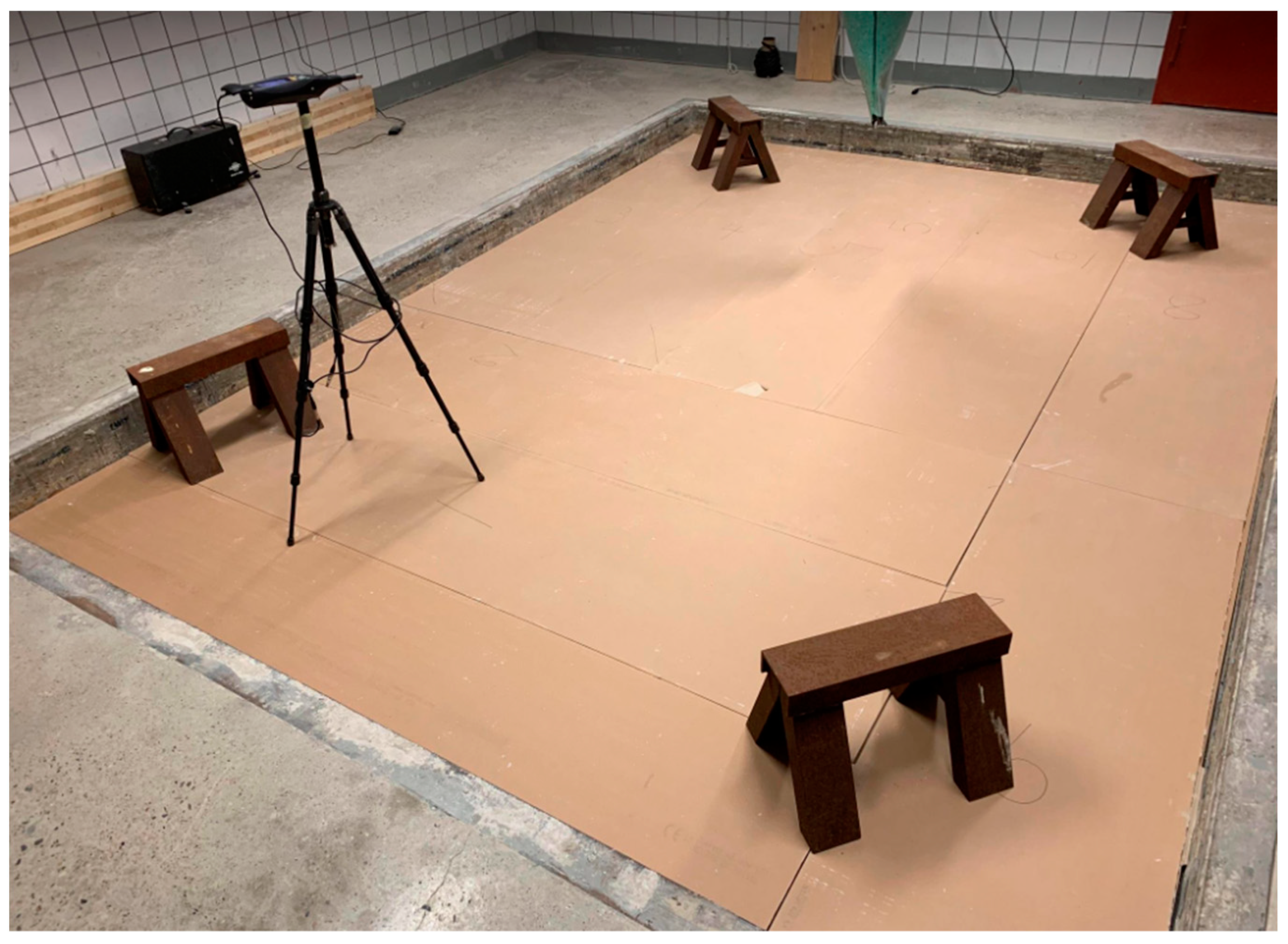
2. Materials and Methods
- is the measured sound pressure level in the sending (source) room in dB;
- is the measured sound pressure level in the receiving room in dB;
- is the sample area of the testing partition in m2, which is 12.3 m2;
- is the equivalent sound absorption area of the receiving room in m2.
- is the measured sound pressure level in the receiving room in dB;
- is the reference equivalent sound absorption area, equal to 10 m2.
3. Results
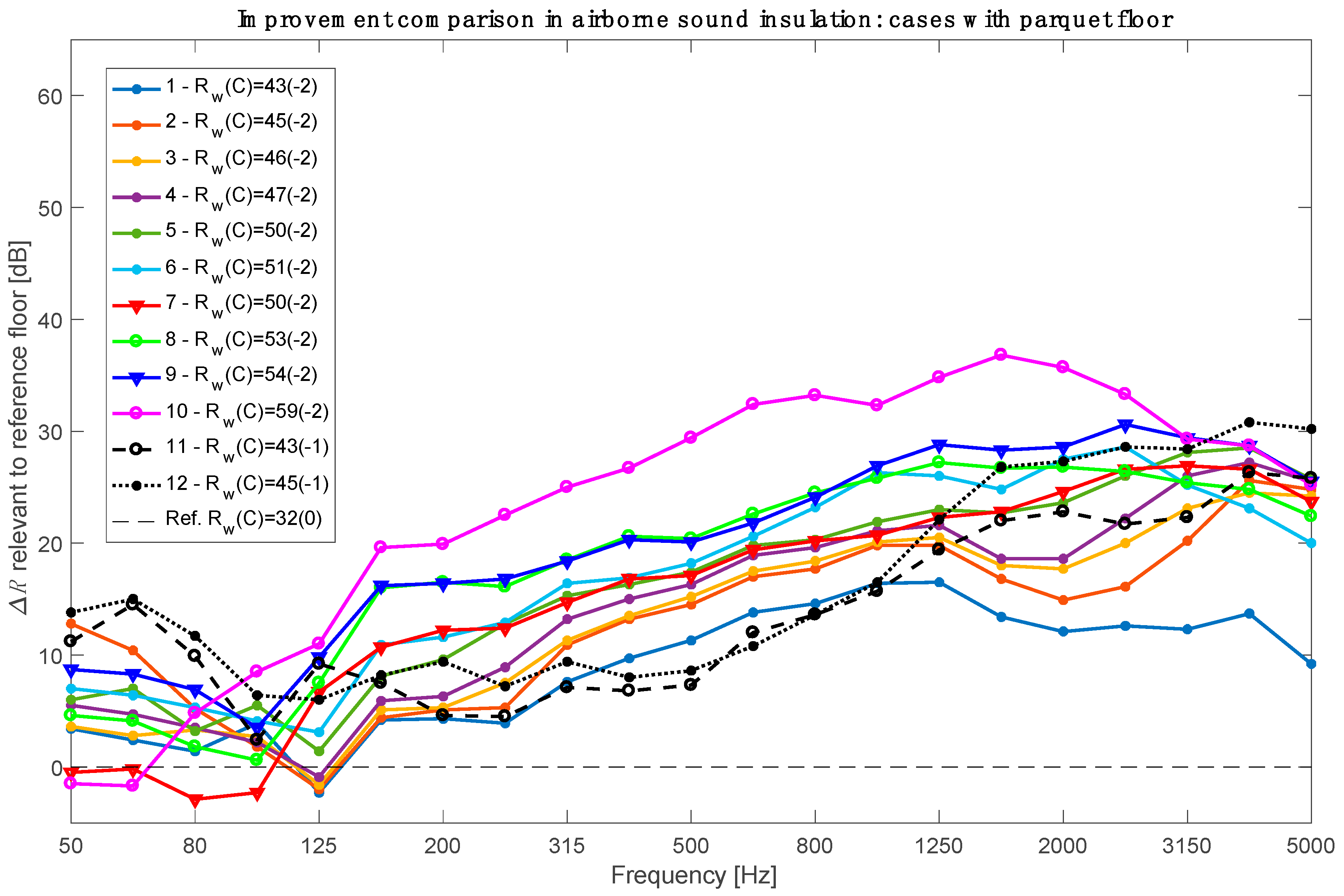
3.1. Airborne Sound Insulation Comparison
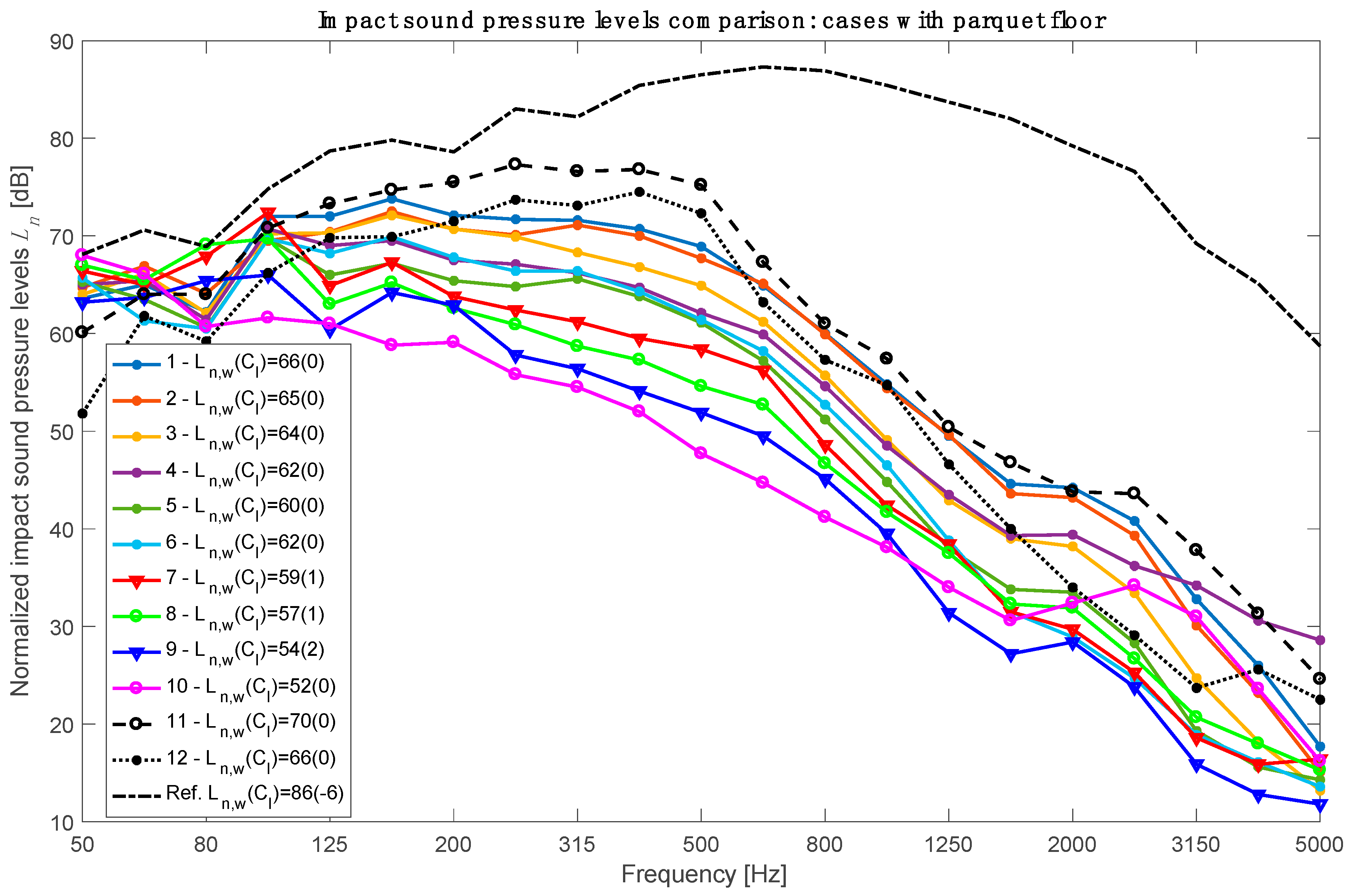
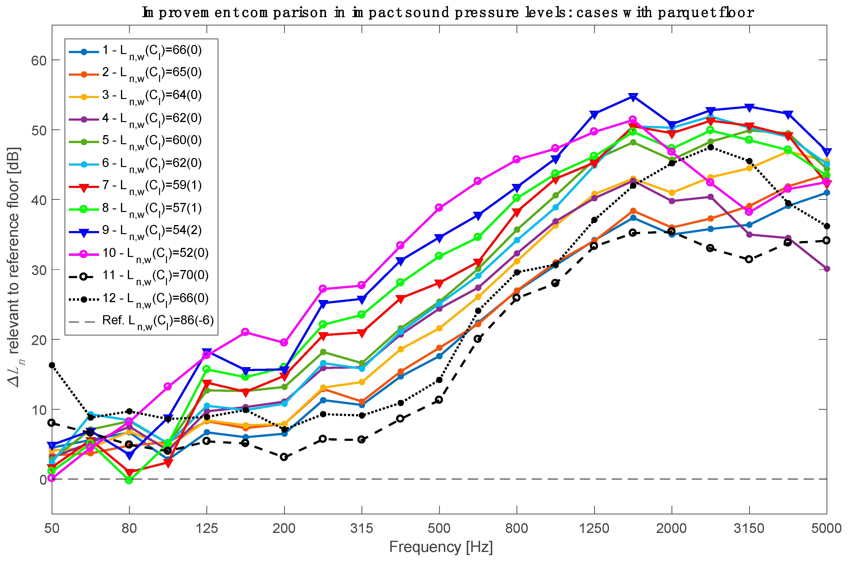
3.2. Impact Sound Insulation Comparison
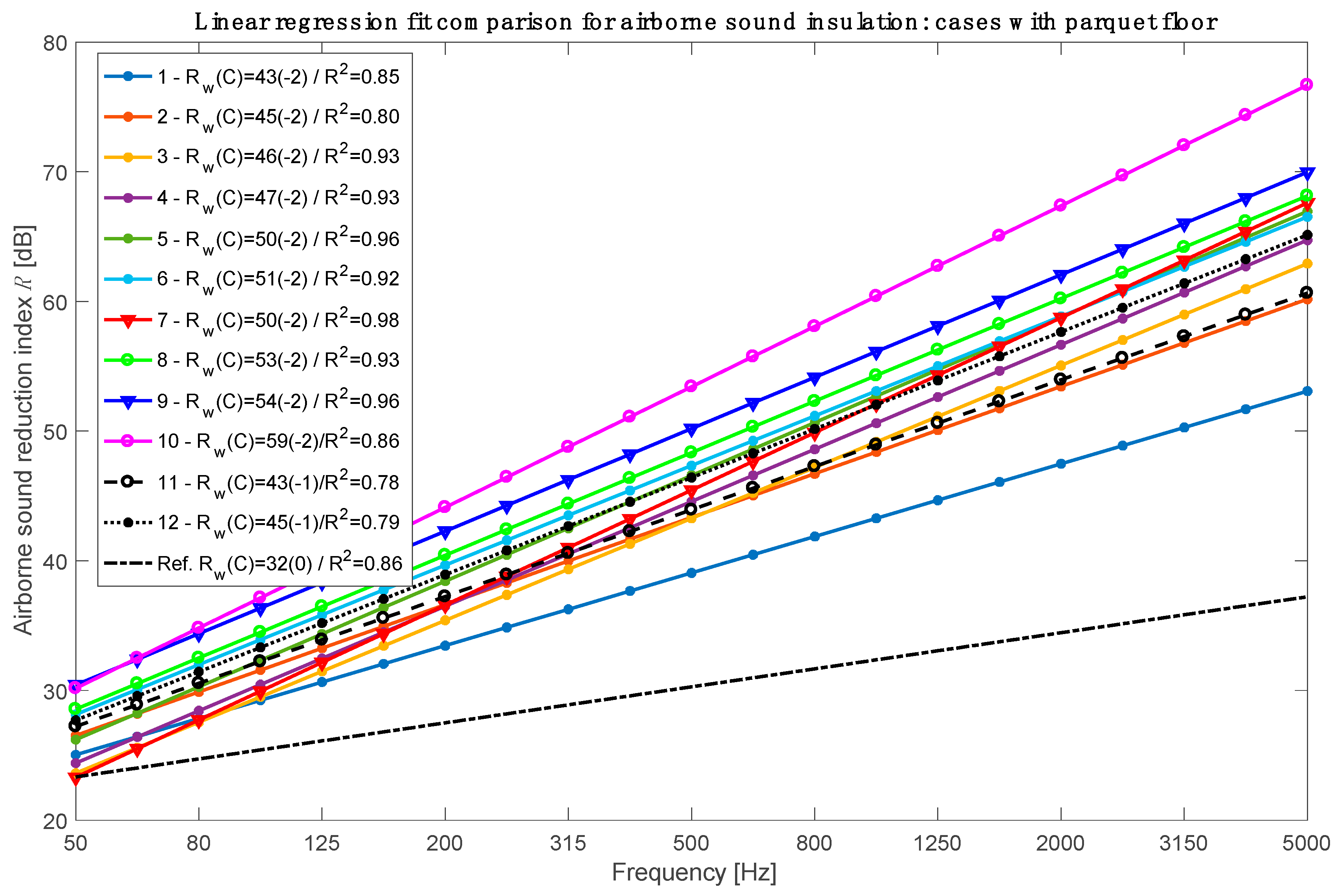
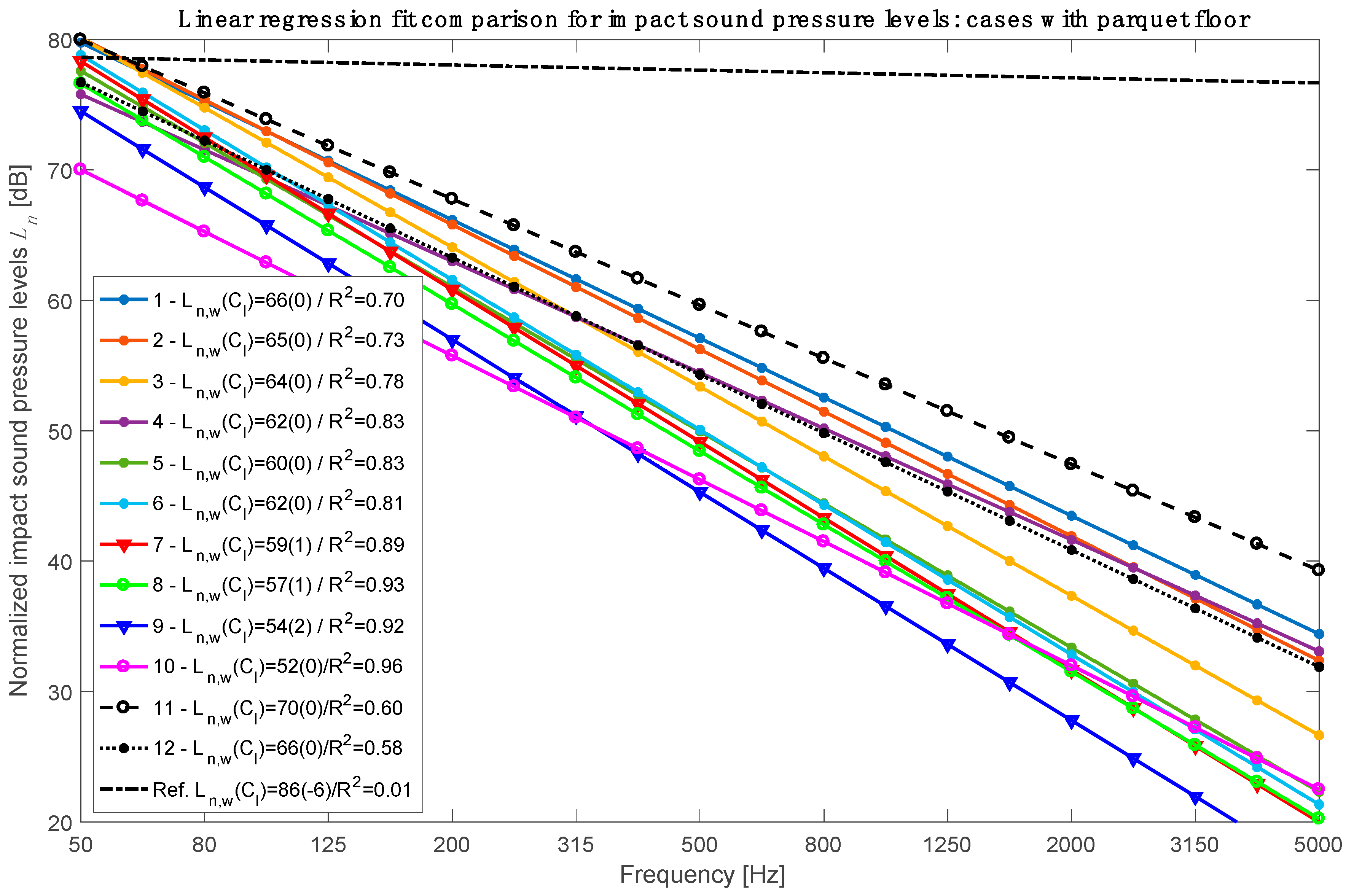
3.3. Linear Regression Model Comparison
4. Discussion
- -
- The location of the first eigenfrequencies of the combined system of additional layers;
- -
- -
5. Conclusions
Supplementary Materials
Author Contributions
Funding
Data Availability Statement
Acknowledgments
Conflicts of Interest
Appendix A


References
- Ni, C.; Popovski, M. Mid-Rise Wood-Frame Construction Handbook; Special Publication SP-57 E; FP Innovations: Pointe Claire, QC, Canada, 2015. [Google Scholar]
- Homb, A.; Guigou-Carter, C.; Rabold, A. Impact sound insulation of cross-laminated timber/massive wood floor constructions- Collection of laboratory measurements and result evaluation. Build. Acoust. 2017, 24, 35–52. [Google Scholar] [CrossRef]
- Morandi, F.; DeCesaris, S.; Garai, M.; Barbaresi, L. Measurement of flanking transmission for the characterisation and classification of cross laminated timber junctions. Appl. Acoust. 2018, 141, 213–222. [Google Scholar] [CrossRef]
- Qian, C.; Ménard, S.; Bard Hagberg, D.; Kouyoumji, J.-L.; Negreira, J. Calibration of the ISO tapping machine for finite-element prediction tool on a wooden-base floor. Build. Acoust. 2019, 26, 157–167. [Google Scholar] [CrossRef]
- Jayalath, A.; Navaratnam, S.; Gunawardena, T.; Mendis, P.; Aye, L. Airborne and impact sound performance of modern lightweight timber buildings in the Australian construction industry. Case Stud. Constr. Mater. 2021, 15, e00632. [Google Scholar] [CrossRef]
- Malo, K.A.; Abrahamsen, R.B.; Bjertnæs, M.A. Some structural design issues of the 14-storey timber framed building “Treet” in Norway. J. Wood. Prod. 2016, 74, 407–424. [Google Scholar] [CrossRef] [Green Version]
- Florisson, S.; Vessby, J.; Ormarsson, S. A three-dimensional numerical analysis of moisture flow in wood and of the wood’s hygro-mechanical and visco-elastic behaviour. Wood Sci. Technol. 2021, 55, 1269–1304. [Google Scholar] [CrossRef]
- Bettarello, F.; Gasparella, A.; Caniato, M. The Influence of Floor Layering on Airborne Sound Insulation and Impact Noise Reduction: A Study on Cross Laminated Timber (CLT) Structures. Appl. Sci. 2021, 11, 5938. [Google Scholar] [CrossRef]
- Di Bella, A.; Mitrovic, M. Acoustic Characteristics of Cross-Laminated Timber Systems. Sustainability 2020, 12, 5612. [Google Scholar] [CrossRef]
- Ljunggren, F.; Ågren, A. Potential solutions to improved sound performance of volume based lightweight multi-storey timber buildings. Appl. Acoust. 2011, 72, 231–240. [Google Scholar] [CrossRef]
- Forssén, J.; Kropp, W.; Brunskog, J.; Ljunggren, S.; Bard, D.; Sandberg, G.; Ljunggren, F.; Ågren, A.; Hallström, O.; Dybro, H.; et al. Acoustics in Wooden Buildings; State of the art 2008, Vinnova project 2007-01653, Report 2008:16, SP Trätek; Technical Research Institute of Sweden: Stockholm, Sweden, 2008. [Google Scholar]
- Ljunggren, F.; Simmons, C.; Hagberg, K. Correlation between sound insulation and occupants’ perception—Proposal of alternative single number rating of impact sound. Appl. Acoust. 2014, 85, 57–68. [Google Scholar] [CrossRef]
- Vigran, T.E. Building Acoustics; Taylor & Francis Group: Abingdon, UK, 2008. [Google Scholar]
- Vardaxis, N.-G.; Bard Hagberg, D. Review of acoustic comfort evaluation in dwellings—Part III: Airborne sound data associated with subjective responses in laboratory tests. J. Build. Acoust. 2018, 25, 289–305. [Google Scholar] [CrossRef]
- Rasmussen, B. Sound insulation between dwellings—Requirements in building regulations in Europe. Appl. Acoust. 2010, 71, 373–385. [Google Scholar] [CrossRef]
- Ljunggren, F.; Simmons, C.; Öqvist, R. Correlation between sound insulation and occupants’ perception—Proposal of alternative single number rating of impact sound—Part II. Appl. Acoust. 2017, 123, 143–151. [Google Scholar] [CrossRef]
- Milford, I.; Høsøien, C.O.; Løvstad, A.; Rindel, J.H.; Klæboe, R. Socio-acoustic survey of sound quality in Dwellings in Norway. In Proceedings of the Inter-Noise 2016, Hamburg, Germany, 21 August 2016. [Google Scholar]
- Vardaxis, N.-G.; Bard, D. Acoustic comfort assessment in heavyweight residential buildings: Acoustic data associated to subjective responses. In Proceedings of the 23rd International Congress on Acoustics: Integrating 4th EAA Euroregio, ICA 2019, Aachen, Germany, 9–23 September 2019. [Google Scholar]
- ISO 717; Acoustics—Rating of Sound Insulation in Buildings and of Buildings Elements—Part 1: Airborne Sound Insulation; International Organization for Standardization: Geneva, Switzerland, 2020.
- ISO 717; Acoustics—Rating of Sound Insulation in Buildings and of Buildings Elements—Part 2: Impact Sound Insulation; International Organization for Standardization: Geneva, Switzerland, 2020.
- Milojević, M.; Damnjanović, E.; Nefovska-Danilović, M.; Marjanović, M. Effects of material uncertainties on vibration performance of cross laminated timber floors. Build. Mater. Struct. 2021, 64, 153–157. [Google Scholar] [CrossRef]
- Hagberg, K.; Bard, D. Sound Insulation Descriptors in Europe—Special Rules Complicate Harmonization within Lightweight Industry. J. Build. Acoust. 2010, 17, 277–290. [Google Scholar] [CrossRef]
- Hongisto, V.; Virjonen, P.; Maula, H.; Saarinen, P.; Radun, J. Impact sound insulation of floating floors: A psychoacoustic experiment linking standard objective rating and subjective perception. J. Build. Environ. 2020, 184, 107225. [Google Scholar] [CrossRef]
- Wuyts, D.; Crispin, C.; Ingelaere, B.; Van Damme, M. Laboratory Sound Insulation Measurements of Improved Timber Floor Constructions: A Parametric Survey. Build. Acoust. 2006, 13, 311–325. [Google Scholar] [CrossRef]
- Caniato, M.; Gasparella, A.; Bettarello, F.; Santoni, A.; Fausti, P.; Granzotto, N.; Bécot, F.X.; Chevillotte, F.; Jaouen, L.; Borello, G.; et al. A reliability study concerning the acoustic simulations of timber elements for buildings. Constr. Build. Mater. 2021, 315, 125765. [Google Scholar] [CrossRef]
- Santoni, A.; Davy, J.L.; Fausti, P.; Bonfiglio, P. A review of the different approaches to predict the sound transmission loss of building partitions. Build. Acosutics 2020, 27, 253–279. [Google Scholar] [CrossRef]
- Negreira, J.; Trollé, A.; Jarnerö, K.; Bard, D. Psycho-vibratory evaluation of timber floors—Towards the determination of design indicators of vibration acceptability and vibration annoyance. J. Sound Vib. 2015, 340, 383–408. [Google Scholar] [CrossRef]
- Qian, C.; Ménard, S.; Bard Hagberg, D.; Negreira, J. Development of vibroacoustic stochastic finite element prediction tool for a CLT floor. Appl. Sci. 2019, 9, 1106. [Google Scholar] [CrossRef] [Green Version]
- Bader Eddin, M.; Ménard, S.; Bard Hagberg, D.; Kouyoumji, J.-L.; Vardaxis, N.-G. Prediction of Sound Insulation Using Artificial Neural Networks—Part I: Lightweight Wooden Floor Structures. Acoustics 2022, 2022, 203–226. [Google Scholar] [CrossRef]
- ISO 10140; Acoustics—Laboratory Measurement of Sound Insulation of Building Elements—Part 5: Requirements for Test Facilities and Equipment; International Organization for Standardization: Geneva, Switzerland, 2021.
- Brandner, R.; Flatscher, G.; Ringhofer, A.; Schickhofer, G.; Thiel, A. Cross Laminated Timber (CLT): Overview and development. Eur. J. Wood Prod. 2016, 74, 331–351. [Google Scholar] [CrossRef]
- Fink, G.; Kohler, J.; Brandner, R. Application of European design principles to cross laminated timber. Eng. Struct. 2018, 171, 934–943. [Google Scholar] [CrossRef]
- Caniato, M.; Bettarello, F.; Granzotto, N.; Marzi, A.; Gasparella, A. A comprehensive vibroacoustic investigation of a cross laminated timber floor. Constr. Build. Mater. 2022, 332, 126303. [Google Scholar] [CrossRef]
- Homb, A.; Guigou-Carter, C.; Hagberg, K.; Schmid, H. Impact sound insulation of wooden joist constructions: Collection of laboratory measurements and trend analysis. Build. Acoust. 2016, 23, 73–91. [Google Scholar] [CrossRef]
- ISO 10140; Acoustics—Laboratory Measurement of Sound Insulation of Building Elements—Part 2: Measurement of Airborne Sound Insulation; International Organization for Standardization: Geneva, Switzerland, 2021.
- ISO 10140; Acoustics—Laboratory Measurement of Sound Insulation of Building Elements—Part 3: Measurement of Impact Sound Insulation; International Organization for Standardization: Geneva, Switzerland, 2021.
- Späh, M.; Hagberg, K.; Bartlomé, O.; Weber, L.; Leistner, P.; Liebl, A. Subjective and Objective Evaluation of Impact Noise Sources in Wooden Buildings. Build. Acoust. 2013, 20, 193–214. [Google Scholar] [CrossRef]
- Hagberg, K. Evaluating field measurements of impact sound. J. Build. Acoust. 2010, 17, 105–128. [Google Scholar] [CrossRef]
- Rindel, J.H. Sound Insulation in Buildings, 1st ed.; CRC Press: Boca Raton, FL, USA, 2017. [Google Scholar]
- Fora-Moncada, A.; Gibbs, B. Prediction of Sound Insulation at Low Frequencies Using Artificial Neural Networks. Build. Acoust. 2002, 9, 49–71. [Google Scholar] [CrossRef]
- Johnson, R.A.; Wichern, D.W. Applied Multivariate Statistical Analysis, 4th ed.; Pearson: London, UK, 2013. [Google Scholar]
- Caniato, M.; Bettarello, F.; Fausti, P.; Ferluga, A. Impact sound of timber floors in sustainable buildings. Build. Environ. 2017, 120, 10–122. [Google Scholar] [CrossRef]
- Persson, P.; Flodén, O.; Danielsson, H.; Peplow, A.; Andersen, L.V. Improved low-frequency performance of cross-laminated timber floor panels by informed material selection. Appl. Acoust. 2021, 179, 108017. [Google Scholar] [CrossRef]
- SS 25267; Acoustics—Sound Classification of Spaces in Buildings—Dwellings; SIS—Swedish Standards Institute: Stockholm, Sweden, 2015.
- ISO 19488; Acoustics—Acoustic Classification of Dwellings; International Organization for Standardization: Geneva, Switzerland, 2021.


| Material | Thickness (mm) | Density (kg/m3) | Mass per Unit Area (kg/m2) |
|---|---|---|---|
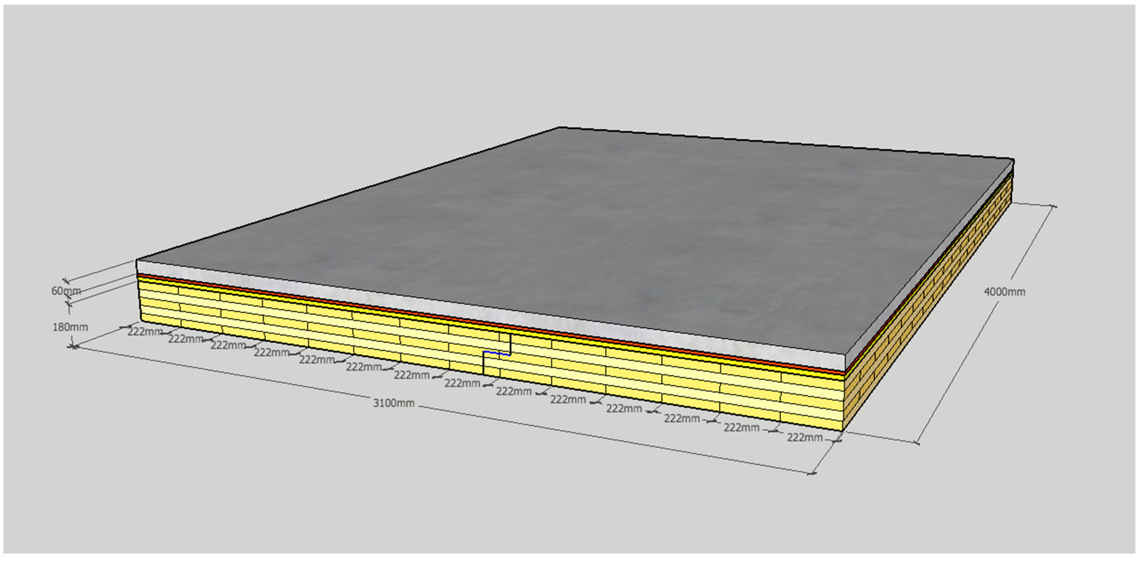
| Cross-laminated timber (CLT) | 180 | 523.9 | 94.3 |
| Gypsum board | 12.5 | 1134.6 | 14 |
| Plywood | 12.5 | 641.0 | 8 |
| Concrete screed 1 | 30 | 1850.0 | 55.5 |
| Concrete screed 2 | 60 | 1850.0 | 111 |
| Glass wool | 20 | 330.1 | 6.6 |
| Vibration isolation mat A | 12 | 359.8 | 4.3 |
| Vibration isolation mat B | 12 | 340.2 | 4.1 |
| Parquet floor (wooden) | 13 | 573.7 | 7.5 |
| FLOOR | SECTION PLAN | CONFIGURATION | ||||||
|---|---|---|---|---|---|---|---|---|
| 0 (REF.) |  | CLT 180 mm | 32 | 32 | 32 | 86 | 80 | 80 |
| 1 |  | 1 * Gypsum 12.5 mm Vibration mat B 12 mm CLT 180 mm | 41 | 40 | 40 | 67 | 67 | 67 |
| Case 1 + Parquet 13 mm | 43 | 41 | 41 | 66 | 66 | 66 | ||
| 2 |  | 1 * Plywood 12.5 mm 1 * Gypsum 12.5 mm Vibration mat B 12 mm CLT 180 mm | 44 | 42 | 42 | 65 | 65 | 65 |
| Case 2 + Parquet 13 mm | 45 | 43 | 43 | 65 | 65 | 65 | ||
| 3 |  | 1 * Gypsum 12.5 mm Vibration mat A 12 mm Vibration mat B 12 mm CLT 180 mm | 45 | 43 | 43 | 65 | 64 | 65 |
| Case 3 + Parquet 13 mm | 46 | 44 | 44 | 64 | 64 | 64 | ||
| 4 |  | 2 * Gypsum 12.5 mm Vibration mat A 12 mm Vibration mat B 12 mm CLT 180 mm | 47 | 45 | 44 | 62 | 62 | 62 |
| Case 4 + Parquet 13 mm | 47 | 45 | 45 | 62 | 62 | 61 | ||
| 5 | 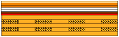 | 2 * Plywood 12.5 mm 2 * Gypsum 12.5 mm Vibration mat A 12 mm Vibration mat B 12 mm CLT 180 mm | 48 | 46 | 46 | 61 | 60 | 61 |
| Case 5 + Parquet 13 mm | 50 | 48 | 48 | 60 | 60 | 61 | ||
| 6 |  | 2 * Gypsum 12.5 mm Vibration mat B 12 mm Vibration mat B 12 mm CLT 180 mm | 50 | 48 | 48 | 62 | 62 | 62 |
| Case 6 + Parquet 13 mm | 51 | 49 | 49 | 62 | 62 | 62 | ||
| 7 | 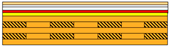 | 2 * Gypsum 12.5 mm Vibration mat B 12 mm Glass wool 20 mm CLT 180 mm | 51 | 49 | 49 | 60 | 60 | 61 |
| Case 7 + Parquet 13 mm | 50 | 48 | 47 | 59 | 60 | 62 | ||
| 8 | 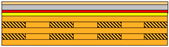 | Concrete screed 30 mm Vibration mat B 12 mm Glass wool 20 mm CLT 180 mm | 54 | 52 | 51 | 60 | 59 | 61 |
| Case 8 + Parquet 13 mm | 53 | 51 | 51 | 57 | 58 | 61 | ||
| 9 | 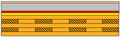 | Concrete screed 60 mm Vibration mat B 12 mm Glass wool 20 mm CLT 180 mm | 54 | 52 | 52 | 61 | 59 | 60 |
| Case 9 + Parquet 13 mm | 54 | 52 | 52 | 54 | 56 | 58 | ||
| 10 * |  | Concrete screed 60 mm Vibration mat B 12 mm Glass wool 20 mm CLT 180 mm Airgap 25 mm 2 * Gypsum 12,5 mm | - | - | - | - | - | - |
| Case 10 + Parquet 13 mm | 59 | 57 | 54 | 52 | 52 | 57 | ||
| 11 |  | Concrete screed 30 mm CLT 180 mm | 43 | 42 | 42 | 93 | 79 | 79 |
| Case 11 + Parquet 13 mm | 43 | 42 | 42 | 70 | 70 | 70 | ||
| 12 |  | Concrete screed 60 mm CLT 180 mm | 46 | 45 | 45 | 87 | 75 | 75 |
| Case 12 + Parquet 13 mm | 45 | 44 | 44 | 66 | 66 | 66 |
Publisher’s Note: MDPI stays neutral with regard to jurisdictional claims in published maps and institutional affiliations. |
© 2022 by the authors. Licensee MDPI, Basel, Switzerland. This article is an open access article distributed under the terms and conditions of the Creative Commons Attribution (CC BY) license (https://creativecommons.org/licenses/by/4.0/).
Share and Cite
Vardaxis, N.-G.; Bard Hagberg, D.; Dahlström, J. Evaluating Laboratory Measurements for Sound Insulation of Cross-Laminated Timber (CLT) Floors: Configurations in Lightweight Buildings. Appl. Sci. 2022, 12, 7642. https://doi.org/10.3390/app12157642
Vardaxis N-G, Bard Hagberg D, Dahlström J. Evaluating Laboratory Measurements for Sound Insulation of Cross-Laminated Timber (CLT) Floors: Configurations in Lightweight Buildings. Applied Sciences. 2022; 12(15):7642. https://doi.org/10.3390/app12157642
Chicago/Turabian StyleVardaxis, Nikolaos-Georgios, Delphine Bard Hagberg, and Jessica Dahlström. 2022. "Evaluating Laboratory Measurements for Sound Insulation of Cross-Laminated Timber (CLT) Floors: Configurations in Lightweight Buildings" Applied Sciences 12, no. 15: 7642. https://doi.org/10.3390/app12157642