Article

Design of a Wide-Beamwidth Pixelated Dielectric Resonator Antenna Using a Modified Stepped-Impedance Filter to Suppress Harmonics

Department of Electrical and Computer Engineering, Sungkyunkwan University, Suwon 16419, Korea
*
Author to whom correspondence should be addressed.
Appl. Sci. 2022, 12(15), 7765; https://doi.org/10.3390/app12157765
Submission received: 18 June 2022 / Revised: 25 July 2022 / Accepted: 26 July 2022 / Published: 2 August 2022
(This article belongs to the Section Electrical, Electronics and Communications Engineering)

Abstract

:
This study designed a wide-beamwidth pixelated dielectric resonator antenna (DRA) combined with a low-pass filter (LPF) to suppress harmonics. The DRA was designed to create a wide-beam pattern with a pixelated structure. The pixelated DRA was optimized by a genetic-learning particle swarm optimization algorithm. To prevent significant higher-mode radiation and harmonics from occurring in the DRA, an LPF was included in its feeding line. The filter had a seventh-order Chebyshev design, and a hybrid step-impedance filter was proposed by modifying the step-impedance filter for use in narrow spaces behind the ground.

1. Introduction

A dielectric resonator antenna (DRA) uses a material with a high dielectric constant as a radiator and possesses high radiation efficiency due to low conduction loss and the absence of surface waves. In addition, it is easy to process, making it suitable for fabricating into various shapes, while antennas can be excited easily via coupling and direct feeding. Generally, DRA has directional beam pattern characteristics in the fundamental mode but wide HPBW characteristics in certain modes. An antenna with a wide HPBW can be used in various fields such as wireless access points, radar, and communication, but there is a problem that the pattern is not flat. Recently, research on wide-beam DRA for solving this problem has being conducted. Studies that have attempted to overcome this problem include [1,2,3,4,5,6]. In [1], unilateral rectangular DRA was designed to simultaneously excite the adjacent TE δ 11 x and TE 2 δ 1 y modes by feeding the probe to make a quasi-omnidirectional radiation pattern. In [2], the ground and DRA were configured in a conformal manner to implement a wide-beamwidth radiation pattern, while in [3], high dielectric constant slabs were attached to the side of the DR to improve the beamwidth at an appropriate location by identifying the field formation inside the DRA. However, the above-noted papers included a wide HPBW only within a single-cut plane (only in the E plane or H plane). In the case of [4], which included wide-beam characteristics in both the E and H planes, the size of the antenna ground was extremely large due to the presence of a sidewall structure for widening the beamwidth, which potentially restricted the application. In [5], a mode with a broad E-plane and a narrow H-plane and a mode with a narrow E-plane and a wide H-plane were analyzed to find frequencies where the two modes are strongly coupled, and designed antennas with wide HPBW on both sides. Although it has the disadvantage of having a very large ground size compared to the wavelength, it was useful to the point that wide HPBW can be achieved if an appropriate mode fusion is achieved. Similar to [5], [6] also combined three excitation modes through irregular geometry to achieve a wide HPBW. Due to the nature of DRAs, in existing studies, unwanted radiation occurred from the use of various high operational band modes; this happened because too many modes were active once the antenna was excited.
In general, by designing a filter on the radio-frequency (RF) stage, unwanted radiation in a section other than the operating band can be suppressed. However, its integration with additional filters increases the overall size of the system, based on the size of the filter itself and the impedance-matching circuit. To overcome these drawbacks, studies have been conducted on filter-integrated antennas (filtennas) [7,8,9,10,11,12,13,14,15]. In [7], a coaxial filter type was designed on a metal feeding rod and integrated with a radiator to suppress harmonics. However, as the order of the filter increased, the height of the cavity also increased. In [8], ferrite was placed on a feeding line to implement filter characteristics, although the addition of ferrite increased the weight of the antenna; therefore, to utilize a large amount of ferrite, the length of the feeding line must be extended. In [9], a band-pass filter was integrated, resulting in a decrease in gain due to a significant transmission line loss. In [10,11], the low pass filter and the band pass filter were integrated into the feeding lines, respectively. Both suppressed broadband harmonics by adding a filter to microstrip patches fed by the CPW method. In [12,13], without adding a filter structure, slots are applied to the patch antenna to form radiation nulls at the bottom and top of the passband. In [14,15], a frequency selective surface (FSS) was attached to the aperture of a typical via feeding microstrip patch antenna to suppress unwanted harmonic radiation. FSS shows low profile characteristics and effective suppression, but it has the disadvantages of significantly increasing the weight and decreasing the gain in the operating band.
Therefore, this study proposes a filter that can be integrated with a feeding line without increasing the size of the system. Additionally, the filter does not degrade the gain of the operating band, and it suppresses unwanted radiation through its sharp skirt characteristics.
In this study, to shape a wide-beamwidth radiation pattern in both the E and H planes, respectively, optimization was carried out using genetic-learning particle swarm optimization (GLPSO). The GLPSO algorithm introduced in [16] was implemented using MATLAB software. Using VBA Link with CST Studio [17], the height of each pixelated dielectric bar was optimized to provide a broad HPBW. The method of pixelating DRA to make the antenna’s operation in the desired direction through an optimization algorithm has been reported in [18]. In [18], they optimized an 8 × 8 grid square DR using a Genetic Algorithm (GA), and the main purpose of the optimization is the formation of circular polarization and the expansion of bandwidth rather than beam pattern and HPBW.
To prevent radiation of the harmonics and high modes in sections other than the operating band, a modified seventh-order Chebyshev low-pass filter (LPF) was integrated into the feeding line coupled to the DR. It is difficult to integrate a step-impedance filter [19,20] within the narrow space of the DRA ground due to limitations concerning the bending of lines. Therefore, a step-impedance filter was modified using Kuroda’s identities and Richards’ transformation [21]. This was easy to miniaturize and deform, and accordingly, it was confirmed that the maximum boresight gain was suppressed sufficiently to −13.5 dBi in the 4–9 GHz band other than the operating band due to filter integration with the antenna. The simulated S11 under −10 dB was 3.06–3.46 GHz (12.3%), and the measured S11 was 2.96–3.44 GHz (14.7%). The simulated 3-dB beamwidths at 3.25 GHz were 184.6 and 189.3 in the xz and yz planes, respectively, and the measured beamwidths were 187.5 and 168.6 in the xz and yz planes, respectively. In the operation band (3.25–3.35 GHz) with wide HPBW, the total efficiency of the antenna was over 89%.

2. The Design of the Proposed Antenna

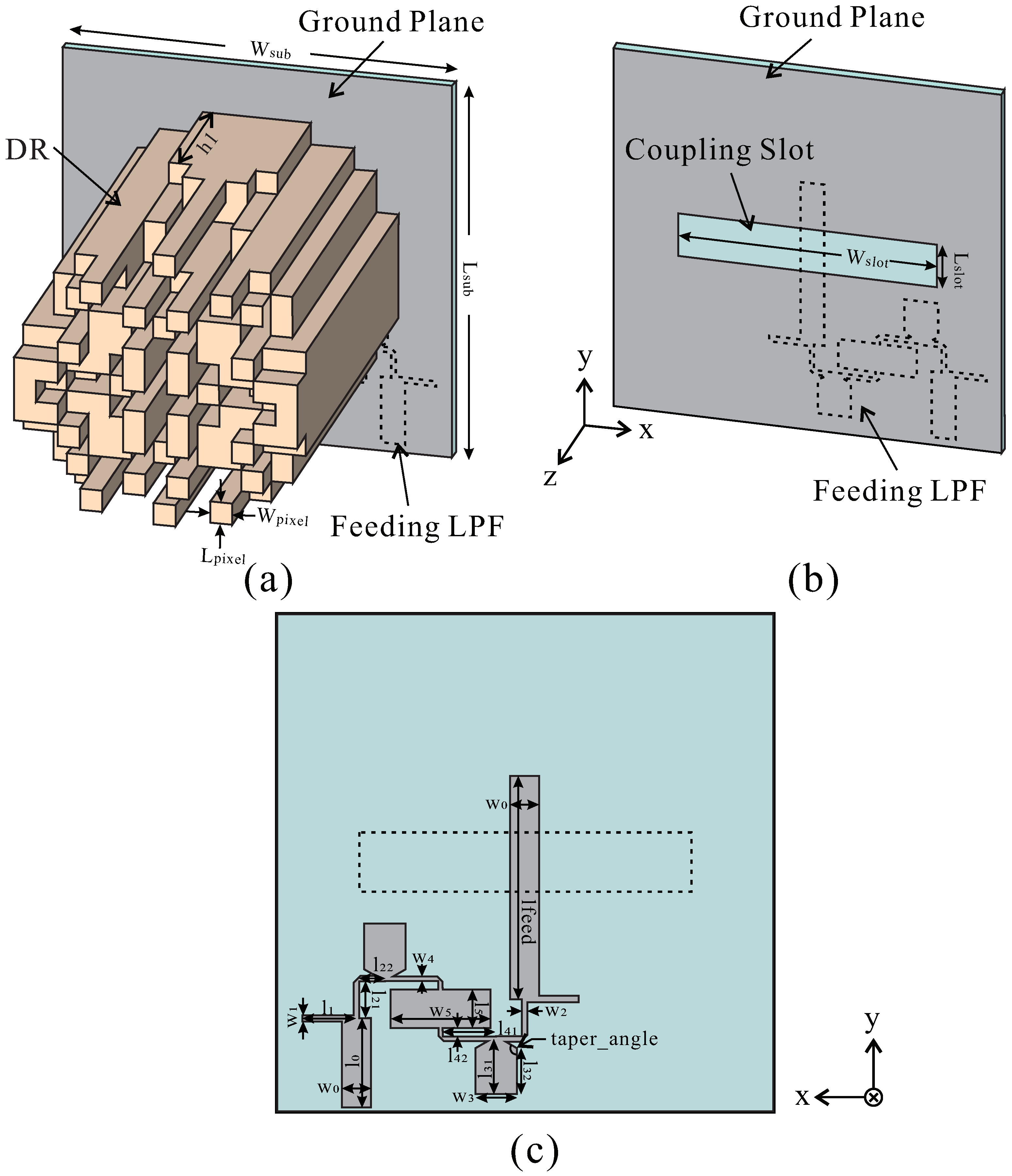
2.1. The Design of the Proposed Antenna with a Wide-Beamwidth Pattern

Figure 1 shows the geometry of the proposed dielectric resonator (DR) and the feeding line. The antenna comprised a fixed alumina DR ( ϵ r = 9.6 ), a ground etched with a rectangular slot, a substrate, and a feeding line integrated with a microstrip LPF.
The DR in Figure 1a comprised a fixed cylinder shape divided by a 13 × 13 grid. There are 137 bars in the grid, each with a size of L p i x e l × W p i x e l = 3.3 × 3.3 mm 2 . The height of the bar was optimized with the GLPSO algorithm to induce a high-order mode with wide HPBW characteristics, and the length of each bar has a value in the range of 5–60 mm. To shorten the optimization time, the grid was divided into quadrants that were symmetrical to the original (first) quadrant. The chromosomes correspond to the height of the rod. The GLPSO included 1000 iterations and 40 populations and was set at a mutation ratio of 0.01. The cost function was set to form a wide beamwidth with a far-field radiation pattern with a constant gain at θ = 90 ∼+90 .
Taconic RF-35 ( ϵ r = 3.5), with a thickness of 1.52 mm and a size of W s u b × L s u b = 60 × 60 mm 2 , was used as a substrate. A slot etched on the ground surface ( W s l o t × l s l o t = 40 × 7 mm 2 ) enabled the coupling of the feeding line and the DR (Table 1).
A seventh-order Chebyshev LPF, which was integrated with the feeding line and etched onto the back of the substrate, was applied to suppress higher modes, as shown in Figure 1c. To overcome the specificity of the space on the back of the narrow substrate, a structure was used that modified the step-impedance filter. The detailed parameters are shown in Table 2.

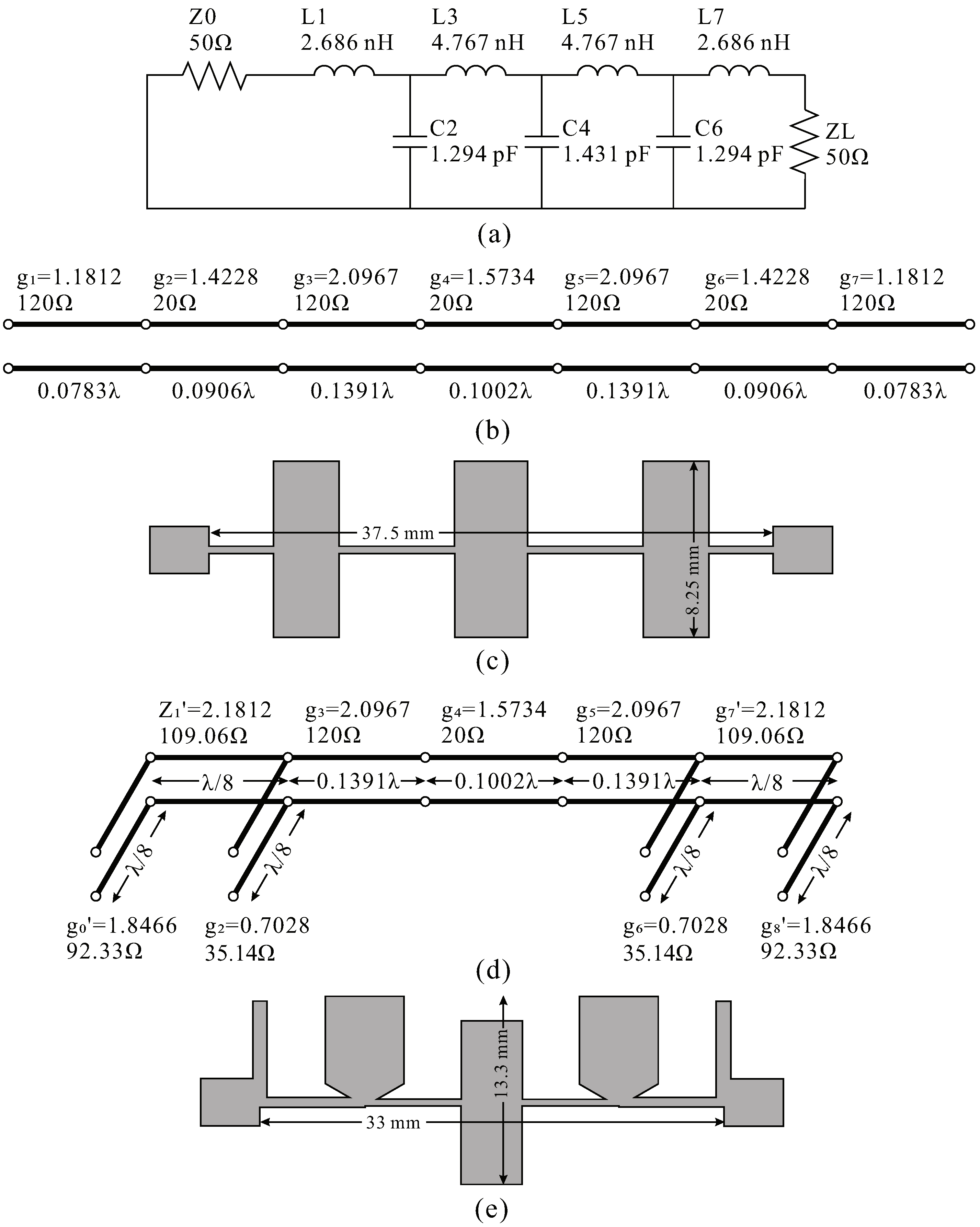
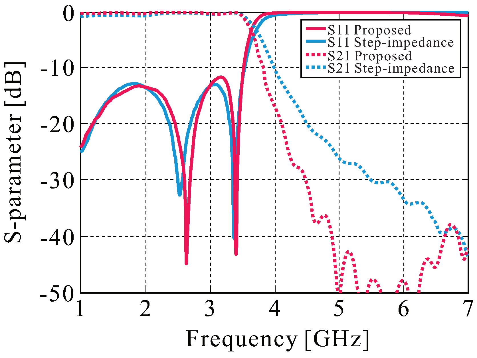
2.2. Designing the Filter for Higher-Mode Suppression

This section presents a microstrip LPF design method aimed at overcoming the narrow space of the ground of the antenna. A micro-stripline type filter was selected so that it could be integrated with the ground of the antenna and operated as a filter in a narrow space. Recent studies of the micro-stripline type filter exist in various studies, as shown in [19,20,21,22,23]. The proposed LPF suppresses the radiation gain of the higher-mode radiation and harmonic resonance arising from the DRA. This study aimed to design a seventh-order Chebyshev LPF with a cut-off frequency of 3.5 GHz and a ripple of 0.1 dB, the equivalent circuits of which are shown in Figure 2a.
The step-impedance [19,20] structure is widely used to implement LPFs in microstrips. The transmission-line model of the filter, designed according to the step-impedance structure, is shown in Figure 2b, and its optimized shape for microstrip implementation is presented in Figure 2c. Considering the substrate characteristics and the linewidth, the high-impedance line (inductive) was set to 120 Ω , while the low impedance line (capacitive) was set to 20 Ω . However, as shown in Figure 2c, the general step-impedance structure cannot escape the linear form from port 1 to port 2. This is because the low impedance line (capacitor) has a very wide linewidth, and even if the narrow linewidth is bent, interference between the capacitive lines will occur.
Since a filter was needed that could be integrated into the narrow space of the antenna base; we modified the step-impedance structure via stub equivalence. In the equivalent circuit shown in Figure 2a, the portions corresponding to Z0, L1, C2, C6, L7, and ZL could be converted into stubs using Richards’ transformation and Kuroda’s identities [21]. The step-impedance structure was maintained because the parts corresponding to L3, C4, and L5 did not interfere with the line deformation. The transmission-line model of the modified step-impedance filter was designed accordingly and is shown in Figure 2d; the optimized shape for the microstrip is presented in Figure 2e.
Figure 3 presents the results of simulating the step-impedance filter structure in Figure 2c and the proposed filter structure in Figure 2e in CST Studio. The two filters reflect almost the same performance, but in the case of the proposed filter, bending the microstrip line is much easier; consequently, it can be placed within a narrow space. Additionally, the skirt characteristics were good, and the filter was optimized and integrated with the antenna. The shape of the proposed LPF could be optimized within a narrow space by easily bending the line. The final optimized filter presented in this paper is illustrated in Figure 4a, and the simulation results are shown in Figure 4b.

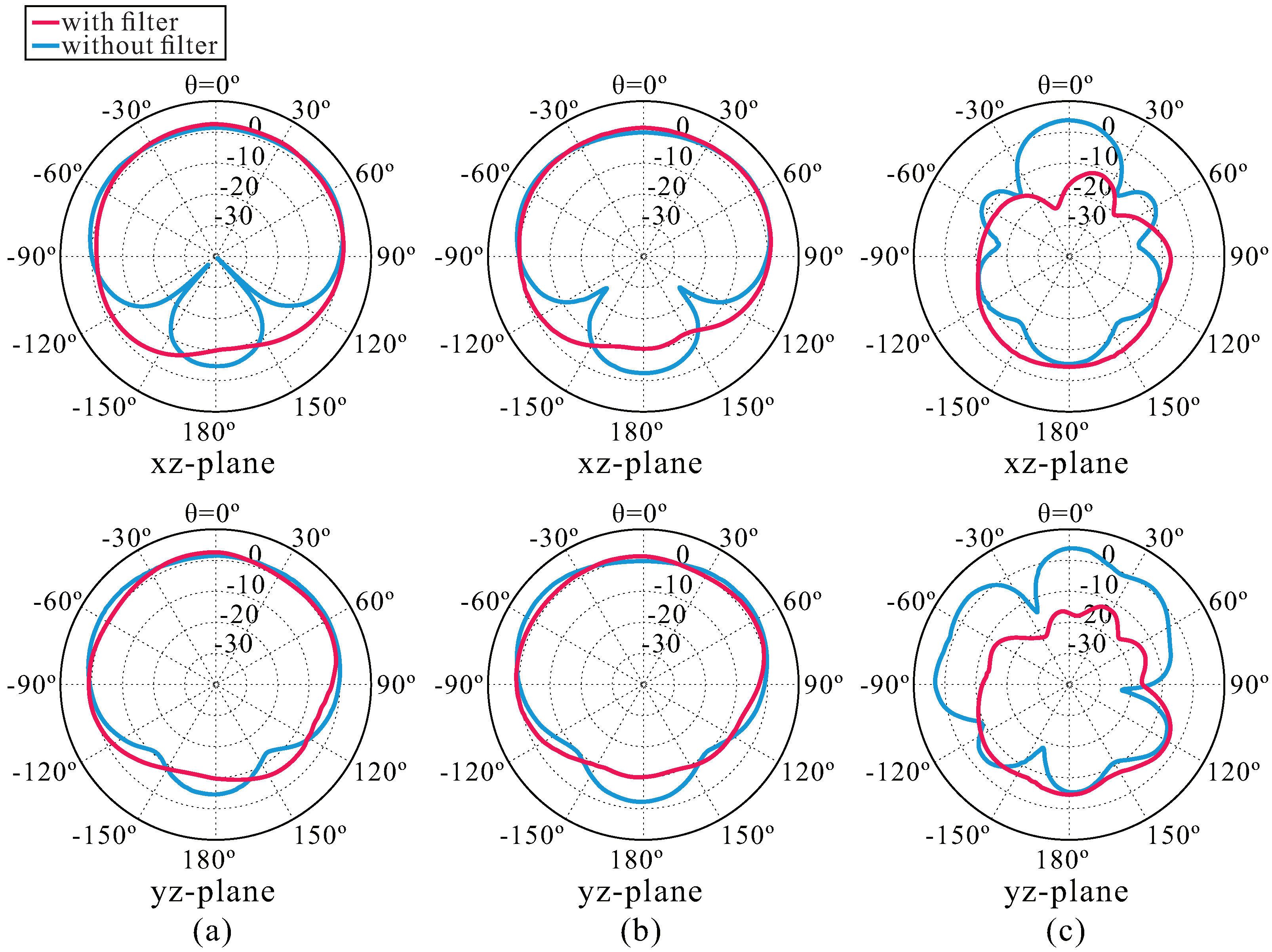
2.3. Simulation Results of the Proposed Antenna

Figure 5 shows the S11, boresight gain, and total efficiency based on the existence of a harmonic suppression filter in the proposed antenna. The simulated S11 (≤−10 dB) bandwidth was 2.96–3.67 (21.5%) and 3.05–3.46 GHz (12.4%), respectively. This shows that the reflection coefficient is completely satisfied in the operating band (3.25–3.35 GHz), where the antenna has a wide HPBW. In the simulation result of the DRA with the filter, the boresight gain of the operating band with wide HPBW is 2.41–1.74 dBi. The reason why the gain seems relatively high at a lower frequency (<3.25 GHz) is that the matching characteristics are poor, but the directivity is high because it operates in the fundamental mode, which does not have a wide HPBW characteristic. Although the gain in operating frequency seems low, as can be seen in Figure 5c, the antenna efficiency has no problem. The antenna gain was comparable in the operating band, regardless of the existence of a filter; nonetheless, radiation in a higher frequency was sufficiently suppressed. This indicated that harmonic suppression had been properly performed, and unwanted radiation was sufficiently suppressed.
According to the simulation, the resulting changes in the radiation pattern of the antenna (based on the presence of a filter) are shown in Figure 6. In the case of the antenna integrated with a filter, the antenna gain in the operating band was reduced slightly due to the loss that occurred in the feeding line, but the pattern was very similar to one without a filter. However, at 6.5 GHz, the harmonic band was sufficiently suppressed, as shown. In addition, based on the results of the simulation, the 3-dB beamwidths of the antenna were 184.6 and 189.3 in the xy and yz planes, respectively, at 3.25 GHz, and 217.1 and 198.2 , respectively, at 3.3 GHz.

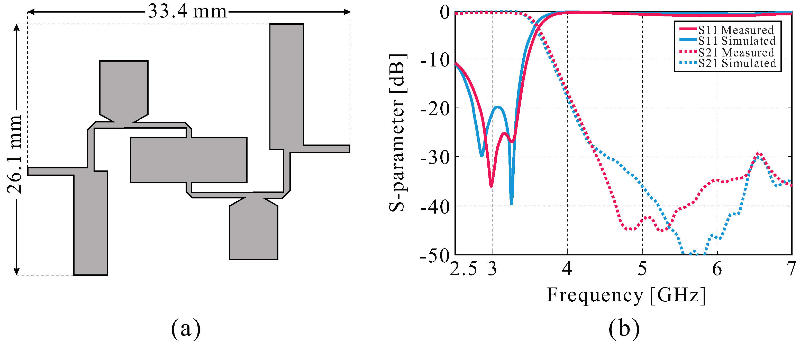
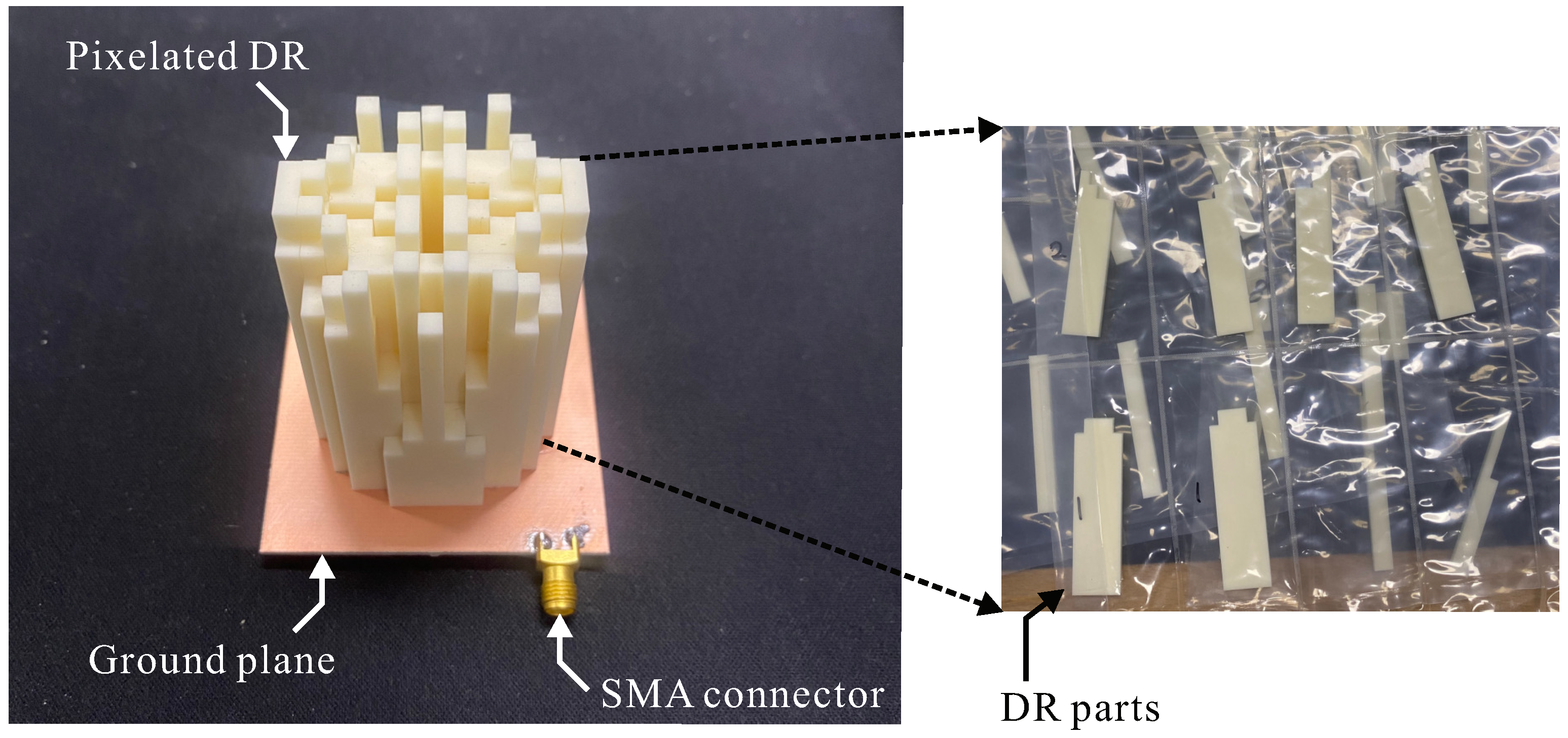
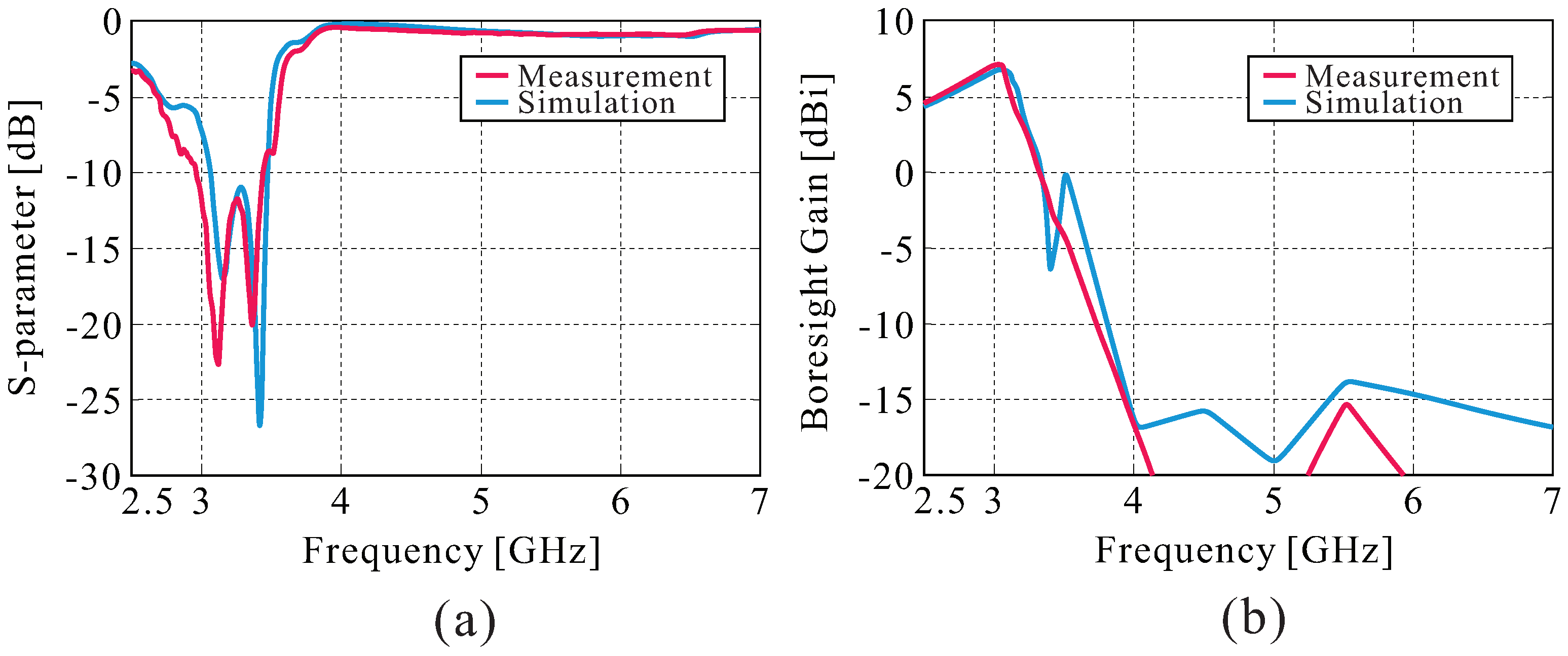
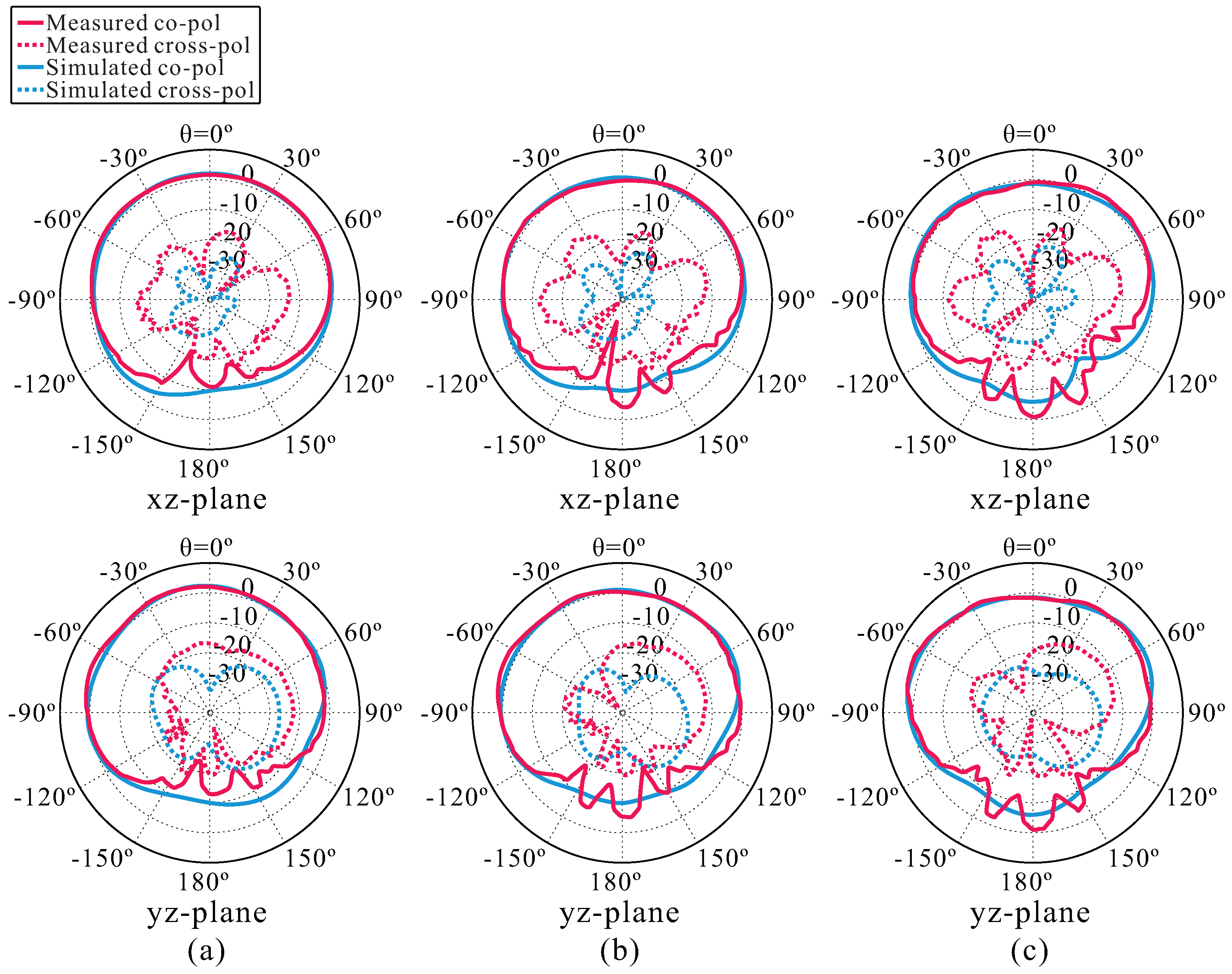
3. Fabrication Results and Measurement

This study fabricated, assembled, and measured a DR, which was split into optimized pixels. The dielectric material was 99% alumina ceramic with a dielectric constant of 9.6 and a loss tangent of 0.0001. Each pixel was divided into an easy form during the milling process and processed into a total of 53 parts. The DR parts were manufactured by attaching adhesives and were attached to the ground plane. The manufactured antenna shape is shown in Figure 7. The under −10 dB reflection bandwidth of the antenna, which was measured using a network analyzer, was 2.96–3.44 GHz (14.7%), and the simulated bandwidth was 3.06–3.46 GHz (12.3%). At an operating bandwidth with wide HPBW (3.25–3.35 GHz), simulated and measured boresight gain of the antenna was 2.41∼−0.81 dBi and 1.84∼−0.19 dBi, respectively. The resulting graphs in Figure 8a,b reveal a good correspondence between the measurements and the simulation data, and the error is due to cable loss and manufacturing tolerance generated during fabrication.
Figure 9 shows the measured and simulated radiation patterns. The two results reveal a good match. Table 3 presents the 3-dB beamwidth according to the frequency in the operation band.
Table 4 shows the comparison of the proposed antenna with the recent studies of wide HPBW DRA. The proposed antenna has a wider HPBW in the E and H-planes than [5] and a narrower E-plane than [3,4] but a wider H-plane HPBW. In addition, although the height of the antenna is higher than those of [3,4,5], the antenna area occupied is much smaller.

4. Conclusions

A modified microstrip step-impedance LPF-integrated wide-beamwidth pixelated DRA was proposed, simulated, fabricated, and tested. To make a wide HPBW radiation pattern, we designed a cylindrical grid pixel DR with a height of 13 × 13 that was optimized by the GLPSO algorithm, which was coded in MATLAB. The filter, which was designed to be integrated with the antenna, was expected to prevent unnecessary system size increases due to the addition of the circuit. The filter is modified through stub-equivalence, and it is possible to achieve the goal of miniaturization of the system by free transforming. The proposed filter has higher skirt characteristics and equal loss of pass band than before. The tested results of the fabricated antenna revealed a −10 dB reflection bandwidth of 14.7% (2.96–3.44 GHz) and a maximum 3-dB beamwidth of 187.46 and 168.63 in the xz and yz planes, respectively, at 3.25 GHz. The proposed antenna with linear polarization and optical beamwidth characteristics is expected to be applied in various fields, such as wireless access points, radar, and communications.

Author Contributions

Writing, D.G.L.; Antenna design and simulation, D.G.L.; Laboratory tests, D.G.L. and T.J.; Software, D.G.L. and T.J.; Writing—Review and Editing, D.G.L. and T.J.; Conceptualization, D.G.L., T.J. and K.C.H. All authors have read and agreed to the published version of the manuscript.

Funding

This research was supported by the Challengeable Future Defense Technology Research and Development Program (912902601) of Agency for Defense Development in 2020.

Institutional Review Board Statement

Not applicable.

Informed Consent Statement

Not applicable.

Data Availability Statement

Not applicable.

Conflicts of Interest

The authors declare no conflict of interest.

References

  1. Guo, L.; Leung, K.W.; Yang, N. Wide-beamwidth unilateral dielectric resonator antenna using higher-order mode. IEEE Antennas Wirel. Propag. Lett. 2018, 18, 93–97. [Google Scholar] [CrossRef]
  2. Boyuan, M.; Pan, J.; Wang, E.; Yang, D. Estimation and utilization of ground effects on conformal dielectric resonator antennas. IEEE Access 2019, 7, 162387–162394. [Google Scholar] [CrossRef]
  3. Sun, S.J.; Jiao, Y.C.; Weng, Z. Wide-beam dielectric resonator antenna with attached higher-permittivity dielectric slabs. IEEE Antennas Wirel. Propag. Lett. 2020, 19, 462–466. [Google Scholar] [CrossRef]
  4. Li, R.Y.; Jiao, Y.C.; Zhang, Y.X.; Zhang, L.; Wang, H.Y. A DRA With Engraved Groove and Comb-Like Metal Wall for Beamwidth Enhancement in Both E-and H-Planes. IEEE Antennas Wirel. Propag. Lett. 2021, 20, 543–547. [Google Scholar] [CrossRef]
  5. Mashhadi, S.H.; Jiao, Y.C.; Chen, J. Broadbeam cylindrical dielectric resonator antenna. IEEE Access 2019, 7, 112653–112661. [Google Scholar] [CrossRef]
  6. Boyuan, M.; Pan, J.; Huang, S.; Yang, D.; Guo, Y. Wide-beam dielectric resonator antennas based on the fusion of higher-order modes. IEEE Trans. Antennas Propag. 2021, 69, 8866–8871. [Google Scholar] [CrossRef]
  7. Yun, J.; Trinh-Van, S.; Park, J.Y.; Yang, Y.; Lee, K.Y.; Hwang, K.C. Cavity-Backed Patch Filtenna for Harmonic Suppression. IEEE Access 2020, 8, 221580–221589. [Google Scholar] [CrossRef]
  8. Lin, C.K.; Chung, S.J. A compact filtering microstrip antenna with quasi-elliptic broadside antenna gain response. IEEE Antennas Wirel. Propag. Lett. 2011, 10, 381–384. [Google Scholar]
  9. Tang, M.C.; Chen, Y.; Shi, T.; Ziolkowski, R.W. Bandwidth-enhanced, compact, near-field resonant parasitic filtennas with sharp out-of-band suppression. IEEE Antennas Wirel. Propag. Lett. 2018, 17, 1483–1487. [Google Scholar] [CrossRef]
  10. Ma, Z.; Vandenbosch, G.A. Wideband harmonic rejection filtenna for wireless power transfer. IEEE Trans. Antennas Propag. 2013, 62, 371–377. [Google Scholar] [CrossRef]
  11. Chin, C.H.; Xue, Q.; Chan, C.H. Design of a 5.8-GHz rectenna incorporating a new patch antenna. IEEE Antennas Wirel. Propag. Lett. 2005, 4, 175–178. [Google Scholar] [CrossRef]
  12. Sung, Y. Simple Patch Antenna with Filtering Function Using Two U-Slots. J. Electromagn. Eng. Sci. 2021, 21, 425–429. [Google Scholar] [CrossRef]
  13. Ramakrishna, C.; Kumar, G.A.R.P.; Sekhar, C. Quadruple Band-Notched Compact Monopole UWB Antenna for Wireless Applications. J. Electromagn. Eng. Sci 2021, 21, 406–416. [Google Scholar] [CrossRef]
  14. Yang, X.; Luyen, H.; Xu, S.; Behdad, N. Design method for low-profile, harmonic-suppressed filter-antennas using miniaturized-element frequency selective surfaces. IEEE Antennas Wirel. Propag. Lett. 2019, 18, 427–431. [Google Scholar] [CrossRef]
  15. Lyou, M.; Kim, G.; Lee, B. Design of Thin and Wideband Microwave Absorbers Using General Closed-Form Solutions. J. Electromagn. Eng. Sci. 2021, 21, 430–438. [Google Scholar] [CrossRef]
  16. Gong, Y.J.; Li, J.J.; Zhou, Y.; Li, Y.; Chung, H.S.H.; Shi, Y.H.; Zhang, J. Genetic learning particle swarm optimization. IEEE Trans. Cybern. 2015, 46, 2277–2290. [Google Scholar] [CrossRef] [PubMed] [Green Version]
  17. Lee, K.; Kim, Y.; Chung, Y.C. Design automation of uhf rfid tag antenna design using a genetic algorithm linked to mws cst. In Proceedings of the 4th IEEE International Symposium on Electronic Design, Test and Applications (DELTA 2008), Hong Kong, China, 23–25 January 2008; pp. 603–606. [Google Scholar]
  18. Trinh-Van, S.; Yang, Y.; Lee, K.Y.; Hwang, K.C. A wideband circularly polarized pixelated dielectric resonator antenna. Sensors 2016, 16, 1349. [Google Scholar] [CrossRef] [PubMed] [Green Version]
  19. Maity, B. Stepped impedance low pass filter using microstrip line for C-band wireless communication. In Proceedings of the International Conference on Computer Communication and Informatics (ICCCI), Coimbatore, India, 7–9 January 2016; pp. 1–4. [Google Scholar]
  20. Kushwah, V.S.; Tomar, G.S.; Bhadauria, S.S. Designing stepped impedance microstrip low-pass filters using artificial neural network at 1.8 GHz. In Proceedings of the International Conference on Communication Systems and Network Technologies, Gwalior, India, 6–8 April 2013; pp. 11–16. [Google Scholar]
  21. Gardner, D.W.; Wickert, M.A. Microwave filter design using radial line stubs. In Proceedings of the IEEE Region 5 Conference, 1988: ‘Spanning the Peaks of Electrotechnology’, Colorado Springs, CO, USA, 21–23 March 1988; pp. 68–72. [Google Scholar]
  22. Basit, A.; Khattak, M.I.; Althuwayb, A.; Nebhen, J. Compact Tri-band Bandpass Filter Based on Asymmetric Step Impedance Resonators for WiMAX and RFID Systems. J. Electromagn. Eng. Sci. 2021, 21, 316–321. [Google Scholar] [CrossRef]
  23. Sung, Y. A novel dual-mode dual-band bandpass filter based on a single ring resonator. J. Electromagn. Eng. Sci. 2020, 20, 91–95. [Google Scholar] [CrossRef]
Figure 1. The configuration of the proposed antenna: (a) overall view, (b) substrate view, and (c) back side-cut view of the substrate (the xy plane). DR = dielectric resonator. LPF = low-pass filter.
Applsci 12 07765 g001
Figure 2. A seventh-order Chebyshev low-pass filter (LPF). (a) An equivalent circuit of the lumped element model, (b) a transmission-line model of LPF step-impedance, (c) an optimized microstrip line model of LPF step-impedance, (d) a transmission-line model of the proposed LPF, and (e) an optimized microstrip line model of the proposed LPF.
Applsci 12 07765 g002
Figure 3. S-parameter of the proposed seventh-order Chebyshev LPF and step-impedance of the same low-pass filter.
Applsci 12 07765 g003
Figure 4. Proposed filter and the S-parameter. (a) A microstrip line model of the proposed filter optimized for the antenna base and (b) the simulated S-parameter.
Applsci 12 07765 g004
Figure 5. Simulation results of the proposed antenna with and without the filter: (a) the S11, (b) the boresight gain, and (c) total efficiency of the antenna.
Applsci 12 07765 g005
Figure 6. Simulated far-field radiation patterns of the proposed antenna with and without a filter: (a) 3.25, (b) 3.3, and (c) 6.5 GHz.
Applsci 12 07765 g006
Figure 7. A photograph of the fabricated antenna and DR parts.
Applsci 12 07765 g007
Figure 8. Measurement results of the fabricated antenna and the simulation. (a) The reflection coefficient and (b) the boresight gain.
Applsci 12 07765 g008
Figure 9. The far-field radiation pattern of the simulated and fabricated antennas: (a) 3.25, (b) 3.3, and (c) 3.35 GHz.
Applsci 12 07765 g009
Table 1. Optimized height (h1–h137) of the 137 DR bars (unit: millimeters).
Optimized Value
2025552520
506035252525356050
5055453560456035455550
5035555530553055553550
55556055556035605555605555
60605555256025602555556060
60555020552530255520505560
60605555256025602555556060
55556055556035605555605555
5035555530553055553550
5055453560456035455550
506035252525356050
2025552520
Table 2. Antenna parameters (unit: millimeters).
ParameterValueParameterValueParameterValue
w 0 3.5 l 0 10.77 l 41 6.5
w 1 0.74 l 1 6.52 l 42 1.1
w 2 0.63 l 21 4.5 l 5 4.6
w 3 4.99 l 22 3.13lfeed26.88
w 4 0.5 l 31 6.69taper angle 120
w 5 12.05 l 32 5.54
Table 3. The measured boresight gain and 3-dB beamwidth of the proposed antenna.
FrequencyBoresight Gainxz Planeyz Plane
3.251.84 dBi187.46 168.63
3.30.86 dBi184.63 151.42
3.35−0.19 dBi167.76 143.93
Table 4. Comparison between recent works of wide-beamwidth DRA.
Ref.Freq (GHz)E-PlaneH-PlaneAntenna Dimension ( λ 0 )
[3]3.2206 137 0.85 × 0.85 × 0.32
[4]3.5248 148 0.93 × 0.93 × 0.35
[5]6.6138 128 1.34 × 1.34 × 0.35
P r o p . 3.25187 168 0.65 × 0.65 × 0.65
Publisher’s Note: MDPI stays neutral with regard to jurisdictional claims in published maps and institutional affiliations.

