Article

Investigation of Quadrate Fresnel Zone Plates Fabricated by Femtosecond Laser Direct Writing

State Key Laboratory of High Performance Complex Manufacturing, College of Mechanical and Electrical Engineering, Central South University, Changsha 410083, China
*
Author to whom correspondence should be addressed.
Appl. Sci. 2022, 12(15), 7788; https://doi.org/10.3390/app12157788
Submission received: 15 July 2022 / Revised: 31 July 2022 / Accepted: 1 August 2022 / Published: 2 August 2022
(This article belongs to the Special Issue Laser-Based Micro/Nano Manufacturing Technology)

Abstract

:
The circular Fresnel zone plate (FZP) has been extensively used in micro-optics due to its outstanding focusing performance. Despite that, the curved edge of the circular zone has drawbacks limiting its use in terahertz imaging, array generator, and micro/nano-manufacturing. Therefore, a circular structure is not very practical to use. In this paper, Quadrate FZPs were proposed, and diffraction properties of the linear FZP (L-FZP), orthogonal FZP (O-FZP), and square FZP (S-FZP) were studied. Theoretically, the relationship between half side length of S-FZP and the radius of circular FZP is established, and the focal length formula of the S-FZP is derived. The linear and crossline focusing properties of quadrate FZPs were studied experimentally along with simulations. With the addition of blockers and phase shifting, the square and rectangular diffraction patterns were successfully obtained.

1. Introduction

Fresnel zone plate (FZP) with a circular structure is the most widely used zone plate because it has better focusing performance [1,2,3,4,5]. However, the curved edges of the circular zone will cause problems in terahertz imaging and eye medicine [6]. In an array generator and integrated optical circuit, the circular FZPs cannot be 100% array because the pixel arrays are the proper rectangular shape. Therefore, FZP with a circular structure is not suitable for all application scenarios. According to the phase distribution, FZPs can be presented as linear, square, rectangular, or polygonal structures. In the micro/nanomanufacturing process, compared with the curved motion of circular FZP, the process of making linear and square FZP is simpler, with higher processing efficiency, fewer defects, and stronger process stability. Therefore, the quadrate FZPs have been proposed, and more and more researchers are paying attention to them.
Generally, the classical circular FZPs have alternate dark and light cyclic zones. The realization of quadrate FZPs depends on the replacement of rings with lines. Francisco et al. [7] designed quadrate and circular Fresnel zone plate lenses (FZPL) with different numbers of zones, working in transmissive or reflective modes. The quadrate FZPLs were written on the backside of a silicon wafer by maintaining the area of their corresponding circular Fresnel zones. I. V. Minin et al. [8] proposed an improved zoning law for designing a quadrate FZPL. The law resulted in a higher gain when the FZPL was used as an antenna element. It enhances the focusing properties of the square FZPL, which help collimate an incident plane wave. Sabatyan et al. [9,10,11] recently designed a series of FZPs with different structures. They presented a square light beam at the focal plane, which was made through lateral phase-shifted S-FZP bound to horizontal and vertical axes via two perpendicular windows of rectangular shape. Theoretically, a square-shaped light beam with desired side length was generated by adjusting the phase shift parameter and bounded width [12]. The above research was focused on the production of diffractive images. However, the detailed fabrication of the optical lens was ignored.
FZPs can be fabricated using ultrafast laser ablation, lithography, nanoimprinting, electron beams, and reactive ion etching [3,13]. In general, ultrafast laser refers to a pulse width of fewer than 10 ps, with several advantages, such as use in multi-material applications, high peak power density, and small heat-affected zone. Because of this, the ultrafast laser plays an important and extensive role in micro and nano-manufacturing [14]. Kim et al. [15] reported a novel process to directly inscribe an FZPL on the cleaved facet of a stiff clad polymer fiber using a femtosecond pulsed laser in binary optical devices. The fabricated FZP has an exceptionally long focal length of over 600 m. Xu et al. [16] proposed fabricating FZPs on the multimode fiber (MMF) tip by combining femtosecond laser direct writing with coating, polishing, and chemical etching. Twelve Fresnel zones were formed with diameters of 200 μ m , and obtained the minimum beam at 900 μ m from the bottom of FZP. Pierre Delullier et al. [17] investigated the photosensitivity to femtosecond laser irradiation of dedicated chalcogenide glass, and a prototype of Fresnel GRIN lens with a refractive index gradient was fabricated via femtosecond laser direct writing. In this paper, taking the advantages of the femtosecond laser in micromachining, designing and fabricating the linear FZP (L-FZP), orthogonal FZP (O-FZP), and square FZP (S-FZP) via femtosecond laser direct writing were proposed. Classical circular FZPs were introduced for the comparison of diffraction properties. Finally, several phase-shifted quadrate FZPs, a phase-shift block FZP (PB-FZP), and a rectangular PB-FZP were carried out to obtain the squarely focus pattern.

2. Theoretical and Experimental Methods

2.1. Theoretical Approach

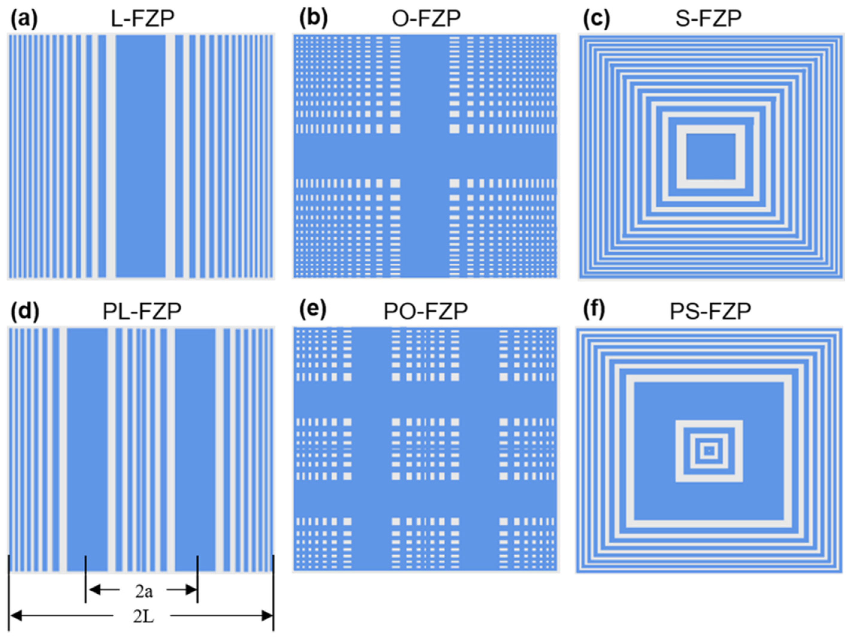
Quadrate FZP refers to a zone plate whose outer contour is square and inner zone is straight, such as linear, orthogonal, and square. The L-FZPs, as a one-dimensional zone plate, have linear focusing. It can be used in a cylindrical lens. After 90° rotation, the L-FZPs overlap the original zone plate vertically, and the O-FZPs, also known as two-dimensional zone plates, can be obtained [18]. Then, the S-FZPs are formed by adjusting the length of O-FZPs by extending it from inside to outside [19,20]. As the most important and complex structure in quadrate FZPs, the S-FZP comprises transparent and opaque zones like circular FZPs.
Figure 1 shows the schematic diagrams of S-FZP and circular FZP. l 1 represents the edge to center distance, which substantially affects the diffraction performance. The half side length of n t h zone is l n , and r n is the radius of circular FZP. Several investigations have focused on the relationship between r n and l n , and, proposed different theories on determining the half side length of the S-FZP when it is converted from the circular FZP. in the first one, González et al. [7] indicated that the area of S-FZP should be the same as circular FZP, as ( 2 l n ) 2 = π r n 2 . Thus, l n 0.886 r n . The second, Alda, J indicated that optimized diffraction performance of polygonal FZP depends on the number of sides s [21], and the determination of l n is related to s, as l n = r n / 1 + tan 2 ( π / s ) 4 . When the polygon is square, then s = 4 , and l n 0.894 r n . The third, Minin et al. [8] proposed that different half side lengths can be obtained via the angle of the l n and r n (shown in Figure 1). When θ 1 = π / 4 , l n = r n cos θ 1 = 0.707 r n ; when θ 2 = π / 8 , l n = r n cos θ 2 = 0.924 r n ; and when θ 3 = 0 , l n = r n cos θ 3 = r n . The diffraction performance primarily determines the transfer from circular FZPs to S-FZPs.
For circular FZPs, focal length f is f 2 + r n 2 = ( f + n λ / 2 ) 2 , Where λ is the wavelength of incident light and n is the number of zones. So the expression for r n can be obtained as r n = n λ f + n 2 λ 2 / 4 , where n 2 λ 2 / 4 represents the spherical aberration. When f n λ / 2 , then r n n λ f . Similarly, when n = 1, f = r 1 2 / λ . However, for S-FZPs, this formula only applies to the rays emitted from the points at the junction of the square and the circle, and the rays from other positions are not considered. When converting the circular FZP into the S-FZP, the position of the focal plane should be kept constant so that the focal length does not change. In this article, l n is set as l n = r n = n λ f proposed by Minin et al. [8] as the transformation law. Hence, the diffraction performance of quadrate FZPs was verified by simulations and experiments presented in the next section.
Moreover, horizontal or vertical phase shifting can obtain the phase shift FZP (PS-FZP). Its diffraction pattern shows new characteristics with the change of structure. Figure 2 presents three quadrate FZPs and the corresponding PS-FZPs. In Figure 2a,d, the center moves to the right and left sides, with the total width of 2L staying the same. The ratio between 2a and 2L is the phase shift parameter α, that is α = a / L ,   ( 1 < α < 1 ) . The phase shift O-FZP (PO-FZP) and phase shift S-FZP (PS-FZP) can be obtained using the same phase-shift method.

2.2. Experimental Methods

FZPs were fabricated in sapphire (Al2O3) via femtosecond laser direct writing. The femtosecond laser has an ultra-short pulse and ultra-high energy peak, which can realize non-hot melt cold processing and high-precision processing, and has a wide range of applications in micro and nano processing. The schematic diagram of the femtosecond laser direct writing experimental system is shown in Figure 3. A Ti-sapphire femtosecond laser with a pulse width of 120 fs, central wavelength of 800 nm, and repetition rate of 1 kHz was used for laser ablation, and it was focused with a 20× objective lens (Nikon, NA = 0.4). The sapphire samples ( 10   mm × 10   mm × 1   mm ) were placed on the 3-DOF movement platform. After processing, the morphology of surfaces was obtained by an optical microscope. The diffractive performance of FZPs was tested by a CCD and a diffraction performance test system [13].

3. Results and Discussion

3.1. Simulation Study on Diffraction Process of S-FZP

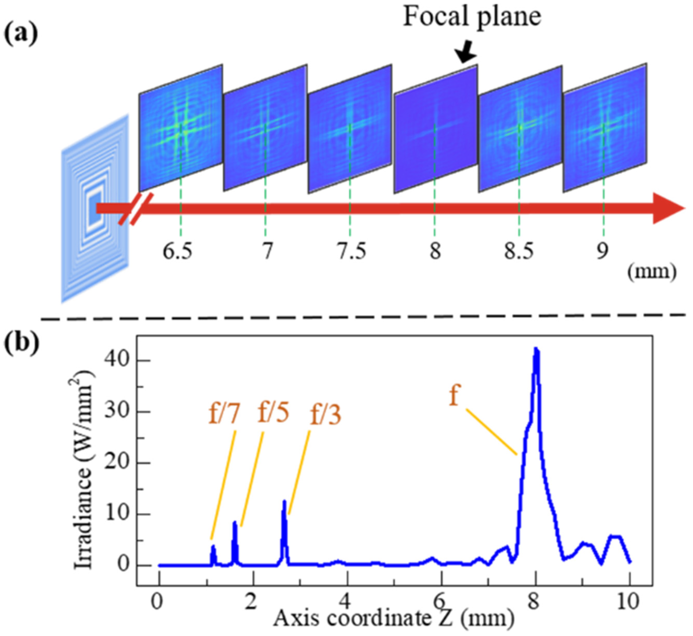
The modeling and simulations of quadrate FZPs and PS-FZPs were conducted in ZEMAX (America, Zemax OpticStudio 17). Figure 4a shows the convergence process of the S-FZP for the beam ( λ = 800   nm ) . The edge-to-center distance was set to 80 μ m and the number of zones to 29. So, the square side length 2L is 862 μm. The simulated results showed that laser beams converge gradually from the FZP plane to the focal plane. At the distance of 8 mm from the FZP plane, the energy convergence is concentrated chiefly with a prominent bright spot and cross line in the center. The linear convergence of energy causes this in the XY direction. After 8 mm, the energy diffuses again. Figure 4b shows the energy distribution along the Z-axis after the incident light passes through S-FZP. It can be seen that the highest energy is at 8 mm, which is the main focal length of S-FZP. Meanwhile, other peaks with decreasing energies appear at 2.67 mm, 1.60 mm, and 1.14 mm. These values are the sub-focal lengths of S-FZP at f / 3 , f / 5 and f / 7 .
As shown in Figure 5, the process of diffraction pattern formation can be seen more clearly by superimposing the focal plane and S-FZP. Along the diagonal, S-FZP can be divided into two triangles of transverse zones and two triangles of longitudinal zones. As can be seen from the triangles of transverse zones, the middle part is a complete linear FZP, so a clear focusing line is formed at the center of the focal plane. The outer region can be segmented into linear FZPs with some zones missing. Because of the absence of the zones, the focal lines formed on the focal plane become scattered. As more zones are missing, less energy is enhanced by diffraction at the center. Therefore, the energy of the focusing line on the focal plane becomes lower and gradually disappears. The same is true of the triangular longitudinal zones. Thus, the center of the diffraction pattern of an S-FZP is a clear crosshair, and the periphery is a widened focusing line.
For circular FZP, with an inner radius of 80 μ m and the incident wavelength of 800 nm, the main focal length is 8 mm, and the sub-focuses are at 2.67 mm, 1.60 mm, and 1.14 mm, according to the equation f = r 1 2 / λ . This is consistent with the primary and sub-focal lengths of S-FZP with 80 μ m edge to center distance. Therefore, when using the third transformation law of Minin et al. [8], the focal plane of S-FZP is at the same position as that of the circular FZP. Similarly, S-FZP has the same focus points as circular FZP. Moreover, the focusing equation of S-FZP is f Q - F Z P = l 1 2 / λ . This not only makes clear the mode of transforming the circular FZP into S-FZP, but also gives the equations of S-FZP focal length directly, which is beneficial for the study of the diffraction performance of quadrate FZP.
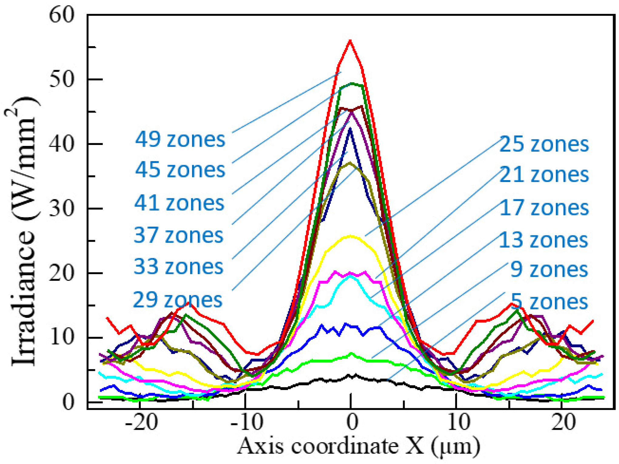
The number of zones is an essential parameter of FZPs, affecting focal point morphology and energy distribution [22]. Several S-FZPs with different zone numbers were modeled to investigate the effects of zone numbers, and the diffraction performance was obtained via ZEMAX simulation. Table 1 compares the diffraction properties of S-FZPs with varying numbers of the zone. The focal depth of FZP gradually decreases from 3 mm to 0.7 mm with increasing zone numbers. As the focal depth decreases, the focal energy gradually centralizes, and the peak power increases with numbers. Figure 6 compares diffraction patterns of focal planes of quadrate FZPs. When the number is too small, a clear cruciform diffraction pattern cannot be produced. At the same time, too many zones make the energy more concentrated at the focus. The diffraction energy of the crossline decreases, which declines the clarity of the crossline. Figure 7 shows the comparison of focal point morphology. From Figure 7 and Table 1, the focal point radius decreases gradually from 18.2 μm to 8.8 μm with the increase in the number. The radius of the focal point has an essential effect on the resolution. The smaller the radius, the higher the resolution. The resolution of S-FZP increases with the increase of the number, which is like that of circular FZP.

3.2. Simulation and Experimental Study on L-FZPs, O-FZPs and S-FZPs

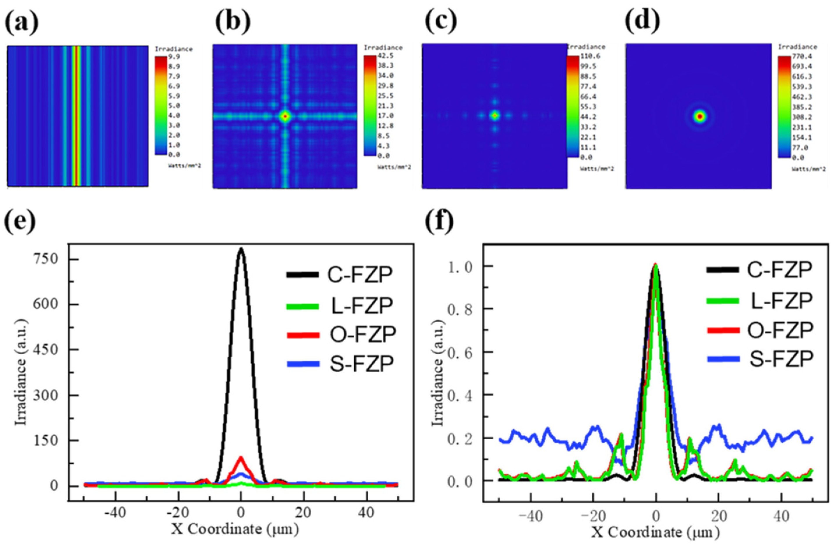
Figure 8a–d shows that the diffraction properties of quadrate FZPs and circular FZP are simulated and compared. All the energy of circular FZP is concentrated at the focus, without any other diffraction pattern. For quadrate FZPs, the light path from the region to the focus is different as the beam passes through at different locations, and therefore there are other diffraction patterns. Figure 8a–c shows simulation diagrams of L-FZP, O-FZP and S-FZP. The edge-to-center distances of the three FZPs are 80 μ m , the numbers of zones are 29, and the main focal lengths are 8 mm . The diffraction pattern of L-PZP is straight, with the highest energy at the central line and a symmetric pattern of lines on both sides, with decreasing energy. The diffraction pattern of O-FZP is crossed dashed lines because O-FZP is composed of vertically crossed L-FZPs. O-FZP is segmented into several narrow linear FZPs, thus forming a series of independent and disconnected focal points arranged in a straight line.
Figure 8e,f compares the focal point energy of the FZPs. It can be seen from Figure 8e that the peak energy of circular FZP is the highest. Similarly, the peak value of quadrate FZPs is lower because the energy of quadrate FZPs is dispersed to the cross line. Figure 8f compares the energy of the three FZPs after normalization. Compared with the circular, linear and orthogonal FZPs, the energy of S-FZP is distributed more on the cross line, and the cross line has the largest energy ratio. The crossline diffraction pattern of S-FZP is clear, which is suitable for the aiming system and other applications for cruciform diffraction pattern.
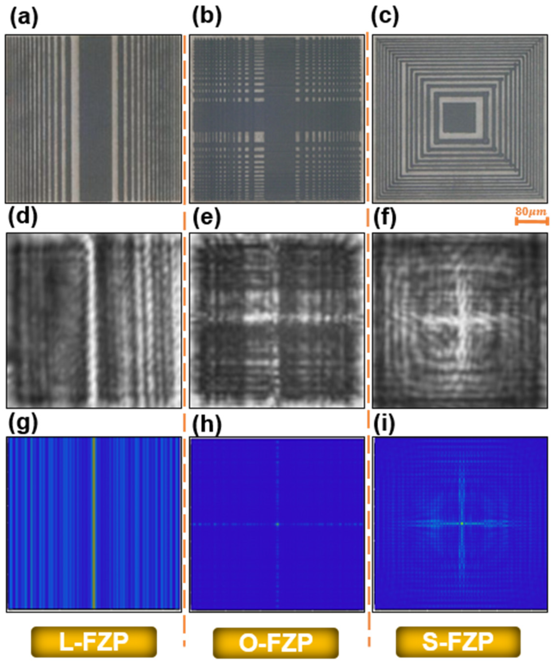
The machining path design and direct writing machining of quadrate FZPs on sapphire material are carried out by a femtosecond laser experimental system. The laser power is 10 mW , and the 3D platform moves at a speed of 1000 μ m / s . Because quadrate FZPs have no curve and radian, the femtosecond laser machining of quadrate FZPs has a simple moving path and less parallel operation. The processing time of 29 zones S-FZP is about 12 min, O-FZP is 8 min, and L-FZP is only 4 min. However, the processing time of the circular FZP is 90 min, which is much longer than that of the quadrate FZPs. Femtosecond laser processing is non-hot melt processing and high precision, so after femtosecond laser fabrication, quadrate FZPs are processed with clear lines (Figure 9a–c). The number of zones of quadrate FZPs is 29, and the edge-to-center distance is 80 μ m . The experimental values are consistent with the theoretical design values.
A diffraction testing system tests the diffraction performance of three FZPs. Figure 9d–f are experimental diffraction patterns of the focal plane, and Figure 9g–i are diffraction patterns simulated by ZEMAX. In comparison, the experimental diffraction pattern and simulation diffraction pattern are consistent. The model and analysis method of the simulation is correct and reliable. The main focal length measured in the experiment is 8 mm, which confirms the equation of S-FZP main focal length, i.e., f Q - F Z P = l 1 2 / λ .

3.3. Simulation and Experimental Study on PS-FZPs

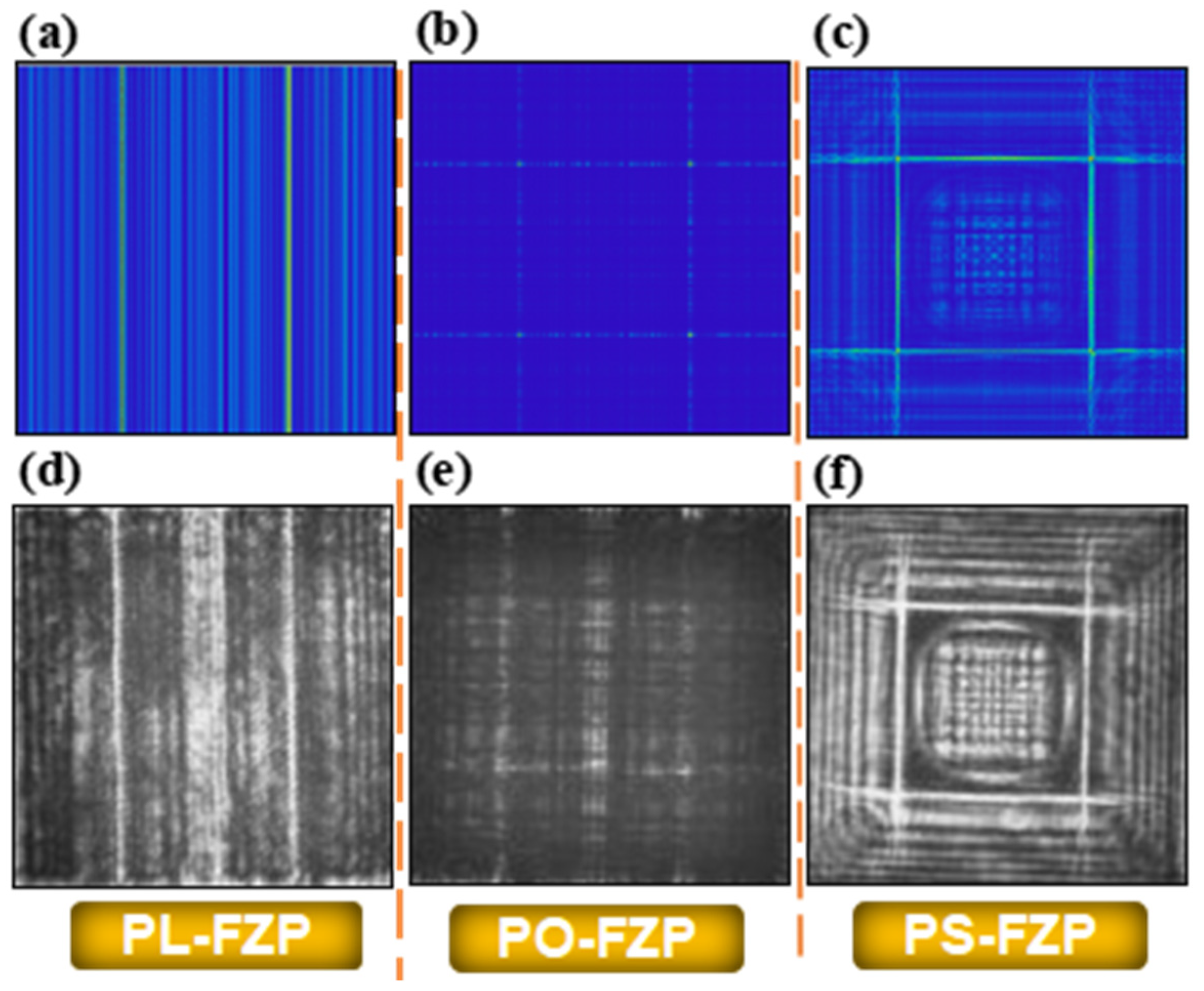
The diffraction pattern of phase-shifted quadrate FZPs is studied by simulation and experiment. In the simulation, the quadrate FZPs with 1.6 mm side length were shifted with phase shift parameter α of 0.4. The diffraction pattern of PL-FZP is shown in Figure 10a. The design of single-line focusing becomes double-line focusing after phase shifting. Figure 10b presents the diffraction pattern of PO-FZP. Two parallel focusing lines on the X and Y direction form a double crossline diffraction pattern. The four points of the diffraction pattern are concentrated, and the diffraction line is intermittent and low in energy. Figure 10c shows the diffraction pattern of PS-FZP, which is also a double-cross line. Compared to the PO-FZP, its diffraction line width is more expansive, and the display is clearer. Three phase-shifted quadrate FZPs were fabricated using a femtosecond laser direct writing and placed in the diffraction performance test system. The diffraction patterns of each FZP are shown in Figure 10d–f. The diffraction pattern obtained by the experiment is consistent with the result of the ZEMAX simulation, and the focus of the double-cross lines is also realized.
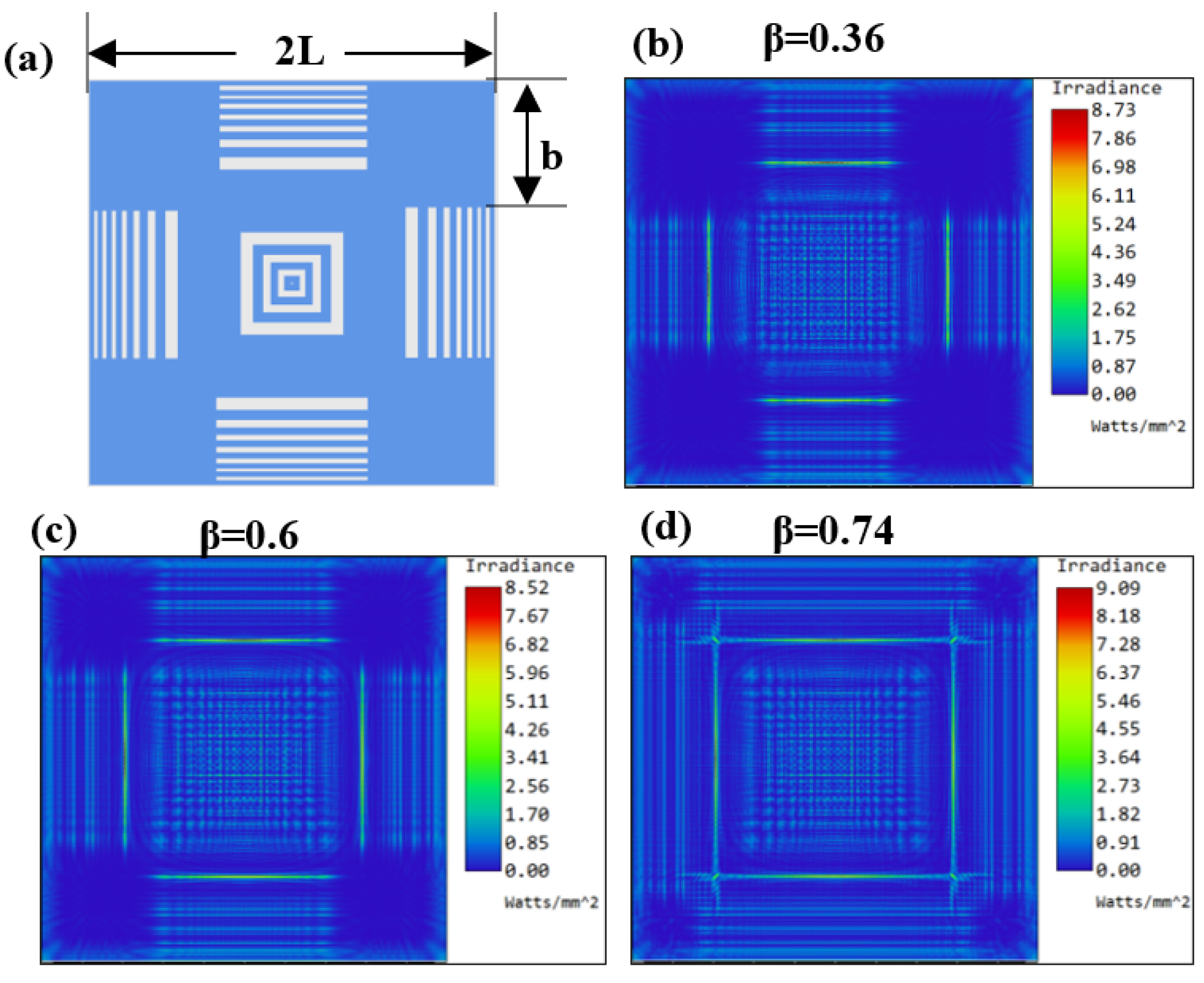
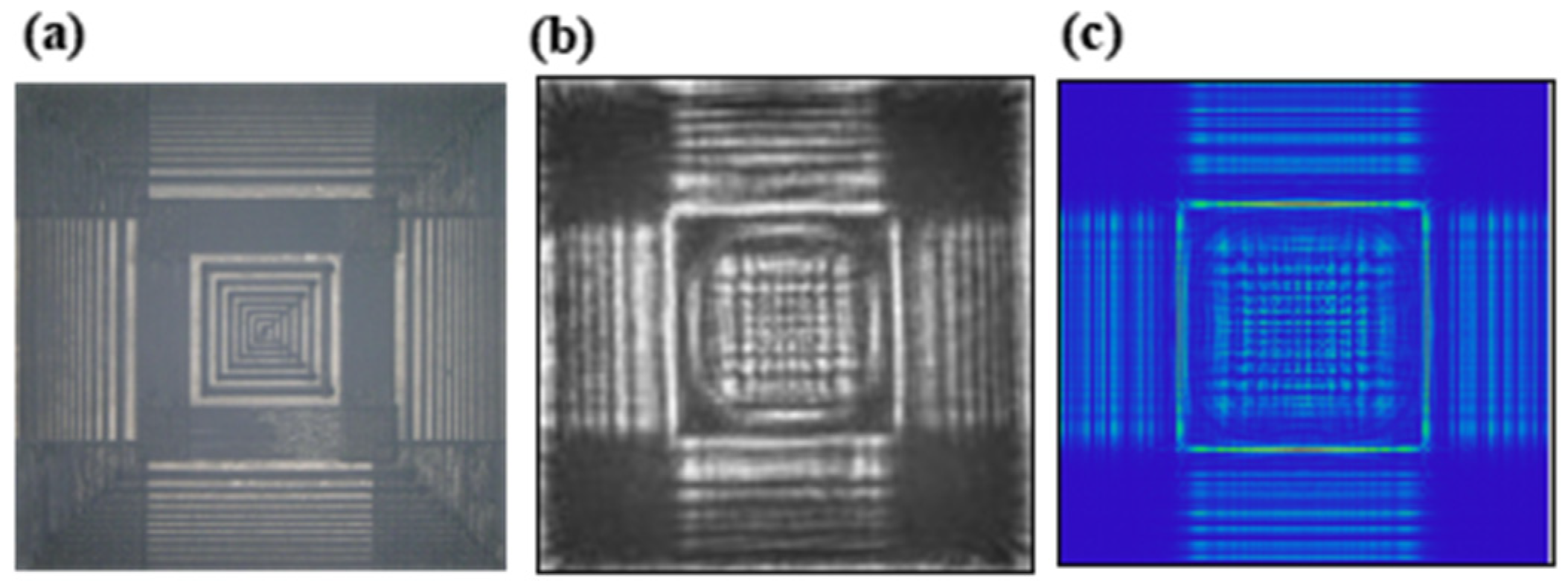
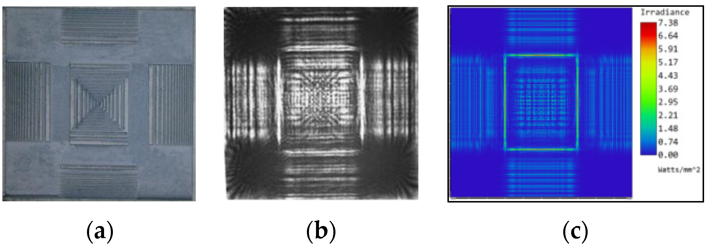
Moreover, square blockers on the four corners of the PS-FZP were introduced to form the phase-shifted block FZP (PB-FZP), as shown in Figure 11a. The side length of blockers is b, and the transmittance is expressed by the transmittance parameter β as β = ( 2 L 2 b ) / 2 L = 1 b / L ,   β ( 0 , 1 ) . The PS-FZP can also be understood as the PB-FZP with β = 1 . When the side length b of blockers is large, the transmittance parameter β is small. Figure 11b–d present the diffraction pattern of PB-FZP with different values of transmittance parameter β. Blockers at the corners block the light, so the length of the diffraction line is shortened. The phase shift parameter α = 0.6 remains unchanged, so the spacing between diffraction lines at four sides does not change. When the transmittance parameter β increases gradually from 0.36 to 0.74, the diffraction line’s length also increases. The PB-FZP is processed by femtosecond laser direct writing (Figure 12a). The phase shift parameter α is 0.6, and the transmittance parameter β is 0.5. As shown in Figure 12b, a clear and bright square pattern is observed in the experimental diffraction pattern, the same as the simulation diffraction pattern. The results demonstrate the fabrication precision of femtosecond laser direct writing and the validity of transformation law for circular FZP to quadrate FZP.
The given results proposed different values of phase shift parameter α in X and Y directions and the corresponding transmittance parameter β to obtain the rectangular diffraction pattern. Figure 13a represents the fs-laser irradiated FZPs with rectangular shapes, and Figure 13b,c shows the diffraction performance and simulated pattern. All boundaries of rectangular FZP have a bright edge in the diffraction pattern, in keeping with the simulated results. The use of parameters from square FZPs to rectangular PB-FZP proved that the focusing equation f Q - F Z P = l 1 2 / λ applies to all the quadrate Fresnel zone plates in designing and manufacturing.

4. Conclusions

In this paper, the structure of circular FZP was optimized, and the diffraction performances of quadrate FZPs were studied. Theoretically, the relationship between half side length L n of S-FZP and radius of circular FZP r n is determined by L n = r n , and the focal length formula of S-FZP is derived as f Q - F Z P = l 1 2 / λ .
The similarities and differences of square, orthogonal, linear, and circular FZPs were studied through simulations and experiments. The quadrate FZPs can achieve linear and cross focus. The influence of zone number on diffraction patterns was also studied. As the number of zones increased, the focal depth and focal point became smaller, and the focal point’s peak reached a larger value. By shifting the phase of quadrate FZPs, the double-cross lines focusing could be realized. Square Fresnel zone plate patterns were obtained by adjusting phase shift and transmittance parameters. Compared with circular FZPs, the quadrate FZPs have more vital stability. They are more suitable for rectangular pixel arrays with beam shaping, optical vortex, array generator applications, and other fields. By adjusting the phase shift parameter in different directions, the rectangular PB-FZPs were fabricated. The simulated results were consistent with the experimental results in diffraction performance.

Author Contributions

Writing-original draft preparation, X.S.; writing-review and editing, F.Z.; investigation, F.Z. and L.D.; methodology, X.S. and L.D.; data curation, J.-a.D.; validation, X.S., F.Z. and L.D.; funding acquisition, X.S. All authors have read and agreed to the published version of the manuscript.

Funding

This research was funded by National Natural Science Foundation of China (Nos. 51875584, 51875585, and 51935013).

Institutional Review Board Statement

Not applicable.

Informed Consent Statement

Not applicable.

Data Availability Statement

The data that support the findings of this study are available from the corresponding author upon reasonable request.

Conflicts of Interest

The authors declare no conflict of interest.

References

  1. Qing, C.; Jürgen, J. Comprehensive focusing analysis of various Fresnel zone plates. J. Opt. Soc. Am. A 2004, 21, 561–571. [Google Scholar]
  2. Kim, J.; Ha, W.; Park, J.; Kim, J.K.; Sohn, I.B.; Shin, W.; Oh, K. Micro Fresnel Zone Plate Lens Inscribed on a Hard Polymer Clad Fiber Using Femtosecond Pulsed Laser. IEEE Photonic Technol. Lett. 2013, 25, 761–763. [Google Scholar] [CrossRef]
  3. Zhou, F.; Sun, X.Y.; Zhong, H.M.; Duan, L.; Hu, Y.W.; Duan, J.; Li, M. Optimization of the focusing characteristics of Fresnel zone plates fabricated with a femtosecond laser. J. Mod. Opt. 2021, 68, 100–107. [Google Scholar] [CrossRef]
  4. Wang, J.H.; Zhang, W.; Cui, Y.W.; Teng, S.Y. Fresnel diffraction by a square aperture with rough edge. Optik 2015, 126, 3066–3071. [Google Scholar] [CrossRef]
  5. Arash, S.; Shima, G. Generation of double line focus and 1D non-diffractive beams using phase shifted linear Fresnel zone plate. Opt. Laser Technol. 2015, 69, 65–70. [Google Scholar]
  6. Zhang, B.Z.; Zhao, D.M. Square Fresnel zone plate with spiral phase for generating zero axial irradiance. Opt. Lett. 2010, 35, 1488–1490. [Google Scholar] [CrossRef]
  7. Gonzalez, F.J.; Alda, J.; Ilic, B.; Boreman, G.D. Infrared antennas coupled to lithographic Fresnel zone plate lenses. Appl. Opt. 2004, 33, 6067–6073. [Google Scholar] [CrossRef]
  8. Minin, I.V.; Minin, O.V.; Petosa, A.; Thirakoune, S. Improved zoning rule for designing square Fresnel zone plate lenses. Microw. Opt. Technol. Lett. 2007, 49, 276–278. [Google Scholar] [CrossRef]
  9. Sabatyan, A.; Rafighdoost, J. Considerable diversity in generation light-arm beams using multi-twisted phase structure zone plate. Opt. Laser Technol. 2018, 107, 24–31. [Google Scholar] [CrossRef]
  10. Sabatyan, A.; Fathi, B. High-efficiency arrays of any desired optical beams using modified grating-based elements. Opt. Quantum Electron. 2018, 50, 338. [Google Scholar] [CrossRef]
  11. Sabatyan, A.; Behjat, Z. Radial phase modulated spiral zone plate for generation and manipulation of optical perfect vortex. Opt. Quantum Electron. 2017, 49, 371. [Google Scholar] [CrossRef]
  12. Anne, S.; Yanwei, L. Phase contrast soft x-ray microscopy using Zernike zone plates. Opt. Express 2008, 16, 1559–1564. [Google Scholar]
  13. Sun, X.Y.; Zhou, F.; Dong, X.R.; Zhang, F.; Liang, C.; Duan, L.; Hu, Y.W.; Duan, J. Fabrication of GaAs micro-optical components using wet etching assisted femtosecond laser ablation. J. Mod. Optic. 2021, 67, 1516–1523. [Google Scholar] [CrossRef]
  14. Lim, K.-D.; Choi, H.-K.; Sohn, I.-B.; Lee, B.-H.; Kim, J.-T. Fabrication of Lensed Optical Fibers for Biosensing Probes Using CO2 and Femtosecond Lasers. Appl. Sci. 2021, 11, 3738. [Google Scholar] [CrossRef]
  15. Low, M.J.; Lee, H.; Lim, C.H.J.; Sandeep, C.S.S.; Murukeshan, V.M.; Kim, S.W.; KIm, Y.J. Laser-induced reduced-graphene-oxide micro-optics patterned by femtosecond laser direct writing. Appl. Surf. Sci. 2020, 526, 146647. [Google Scholar] [CrossRef]
  16. Xu, C.; Zhang, F.; Lu, S.Q.; Zhong, S.S.; Chu, D.K.; Duan, J. Gold filled in Fresnel zone plate fabricated by femtosecond laser on fiber tip. Opt. Fiber Technol. 2021, 64, 102572. [Google Scholar] [CrossRef]
  17. Delullier, P.; Druart, G.; De La Barrière, F.; Calvez, L.; Lancry, M. Femtosecond Laser Direct Writing of Gradient Index Fresnel Lens in GeS2-Based Chalcogenide Glass for Imaging Applications. Appl. Sci. 2022, 12, 4490. [Google Scholar] [CrossRef]
  18. Jiang, Z.; Du, H.P.; Ruan, Y.Z. On the adaptive beam forming performance of a multi-beam antenna. Chin. J. Electron. 2004, 13, 724–727. [Google Scholar]
  19. Rico-Garcia, J.M.; Salgado-Remacha, F.J.; Sanchez-Brea, L.M.; Alda, J. Optimized square Fresnel zone plates for microoptics applications. Model. Asp. Opt. Metrol. II 2009, 7390, 739011. [Google Scholar]
  20. Kim, J.; Kim, H.; Lee, G.Y.; Kim, J.; Lee, B.; Jeong, Y. Numerical and Experimental Study on Multi-Focal Metallic Fresnel Zone Plates Designed by the Phase Selection Rule via Virtual Point Sources. Appl. Sci. 2018, 8, 449. [Google Scholar] [CrossRef] [Green Version]
  21. Alda, J.; Rico-Garcia, J.M.; Lopez-Alonso, J.M.; Lail, B.; Boreman, G. Design of Fresnel lenses and binary-staircase kinoforms of low value of the aperture number. Opt. Commun. 2006, 260, 454–461. [Google Scholar] [CrossRef] [Green Version]
  22. Zhang, Y.; Zheng, C. Axial intensity distribution behind a Fresnel zone plate. Opt. Laser Technol. 2005, 37, 77–80. [Google Scholar] [CrossRef]
Figure 1. The relationship between the half sidelength of S-FZP and the radius of the circular FZP.
Applsci 12 07788 g001
Figure 2. Schematic diagrams of quadrate FZPs: (a) L-FZP; (b) O-FZP; (c) S-FZP; (d) PL-FZP; (e) PO-FZP; (f) PS-FZP.
Applsci 12 07788 g002
Figure 3. Schematic diagram of the femtosecond laser direct writing experimental system.
Applsci 12 07788 g003
Figure 4. Simulation diagram of the energy distribution of S-FZP along the Z-axis: (a) the distribution of the cross-sectional energy; (b) energy profile along with the z-axis.
Applsci 12 07788 g004
Figure 5. Structure and diffraction pattern of S-FZP.
Applsci 12 07788 g005
Figure 6. Diffraction pattern contrast of S-FZPs with different numbers of zones.
Applsci 12 07788 g006
Figure 7. Contrast image of focal point morphology of S-FZPs with different numbers of zones.
Applsci 12 07788 g007
Figure 8. The focal point pattern of FZPs: (a) L-FZP; (b) S-FZP; (c) O-FZP; (d) circular FZP (C-FZP), and the corresponding contrast diagram of focal point energy of FZP: (e) Unnormalized graph; (f) normalized graph.
Applsci 12 07788 g008
Figure 9. The fabricated morphology of (a) L-FZPs (b) O-FZPs (c) S-FZPs; the diffractive performance of corresponding FZPs: (df): experimental patterns; (gi): simulation patterns.
Applsci 12 07788 g009
Figure 10. Diffraction pattern of phase-shifted quadrate FZPs: (ac) Simulated diffraction pattern; (df) experimental diffraction pattern.
Applsci 12 07788 g010
Figure 11. (a) Schematic diagram of PB-FZP; the diffraction pattern of PB-FZP with different values of transmittance parameter β: (b) β = 0.36; (c) β = 0.6; (d) β = 0.74.
Applsci 12 07788 g011
Figure 12. (a) PB-FZP fabricated by femtosecond laser; (b) Experimental focal plane; (c) Simulated Focal plane.
Applsci 12 07788 g012
Figure 13. (a) the rectangular PB-FZPs processing by fs-laser; (b) corresponding diffraction performance; and (c) corresponding simulated results.
Applsci 12 07788 g013
Table 1. Comparison of diffraction properties of S-FZPs with different zone numbers.
Number of zones5913172125293337414549
Focal depth (mm)332.82.41.61.41.11.10.90.70.70.7
Peak power (W/mm2)3.87.711.719.720.025.942.537.245.245.249.556.0
Focus radius (μm)18.214.114.114.813.612.510.910.89.510.09.48.8
Publisher’s Note: MDPI stays neutral with regard to jurisdictional claims in published maps and institutional affiliations.