
Fatigue Testing of Human Flexor Tendons Using a Customized 3D-Printed Clamping System

 , ,
, ,
Abstract
:Featured Application
Abstract
1. Introduction
2. Materials and Methods
3. Results
4. Discussion
Limitations
5. Conclusions
Author Contributions
Funding
Institutional Review Board Statement
Informed Consent Statement
Data Availability Statement
Acknowledgments
Conflicts of Interest
References
- Barber, F.A.; Aziz-Jacobo, J. Biomechanical testing of commercially available soft-tissue augmentation materials. Arthroscopy 2009, 25, 1233–1239. [Google Scholar] [CrossRef] [PubMed]
- Branch, J.P. A tendon graft weave using an acellular dermal matrix for repair of the Achilles tendon and other foot and ankle tendons. J. Foot Ankle Surg. 2011, 50, 257–265. [Google Scholar] [CrossRef] [PubMed]
- Rubin, L.; Schweitzer, S. The use of acellular biologic tissue patches in foot and ankle surgery. Clin. Podiatr. Med. Surg. 2005, 22, 533–552. [Google Scholar] [CrossRef] [PubMed]
- Ellison, M.E.; Duenwald-Kuehl, S.; Forrest, L.J.; Vanderby, R., Jr.; Brounts, S.H. Reproducibility and feasibility of acoustoelastography in the superficial digital flexor tendons of clinically normal horses. Am. J. Vet. Res. 2014, 75, 581–587. [Google Scholar] [CrossRef]
- Bai, Y.; Jin, W.-L. Chapter 25—Fatigue Capacity. In Marine Structural Design, 2nd ed.; Butterworth-Heinemann: Oxford, UK, 2016; pp. 489–507. [Google Scholar] [CrossRef]
- Martin, C.; Sun, W. Fatigue damage of collagenous tissues: Experiment, modeling and simulation studies. J. Long Term Eff. Med. Implant. 2015, 25, 55–73. [Google Scholar] [CrossRef] [Green Version]
- Schechtman, H.; Bader, D.L. Fatigue damage of human tendons. J. Biomech. 2002, 35, 347–353. [Google Scholar] [CrossRef]
- Wren, T.A.; Lindsey, D.P.; Beaupre, G.S.; Carter, D.R. Effects of creep and cyclic loading on the mechanical properties and failure of human Achilles tendons. Ann. Biomed. Eng. 2003, 31, 710–717. [Google Scholar] [CrossRef]
- Schechtman, H.; Bader, D.L. In vitro fatigue of human tendons. J. Biomech. 1997, 30, 829–835. [Google Scholar] [CrossRef]
- Ker, R.F.; Wang, X.T.; Pike, A.V. Fatigue quality of mammalian tendons. J. Exp. Biol. 2000, 203, 1317–1327. [Google Scholar] [CrossRef]
- Shepherd, J.H.; Screen, H.R. Fatigue loading of tendon. Int. J. Exp. Pathol. 2013, 94, 260–270. [Google Scholar] [CrossRef]
- Bowser, J.E.; Elder, S.H.; Rashmir-Raven, A.M.; Swiderski, C.E. A cryogenic clamping technique that facilitates ultimate tensile strength determinations in tendons and ligaments. Vet. Comp. Orthop. Traumatol. 2011, 24, 370–373. [Google Scholar] [CrossRef] [PubMed]
- Steinke, H.; Lingslebe, U.; Bohme, J.; Slowik, V.; Shim, V.; Hadrich, C.; Hammer, N. Deformation behavior of the iliotibial tract under different states of fixation. Med. Eng. Phys. 2012, 34, 1221–1227. [Google Scholar] [CrossRef] [PubMed]
- Scholze, M.; Safavi, S.; Li, K.C.; Ondruschka, B.; Werner, M.; Zwirner, J.; Hammer, N. Standardized tensile testing of soft tissue using a 3D printed clamping system. HardwareX 2020, 8, e00159. [Google Scholar] [CrossRef]
- Scholze, M.; Singh, A.; Lozano, P.F.; Ondruschka, B.; Ramezani, M.; Werner, M.; Hammer, N. Utilization of 3D printing technology to facilitate and standardize soft tissue testing. Sci Rep. 2018, 8, 11340. [Google Scholar] [CrossRef] [PubMed] [Green Version]
- Vella Wood, M.; Casha, A.; Gatt, A.; Formosa, C.; Chockalingam, N.; Grima, J.N.; Gatt, R. 3D Printed Clamps to Study the Mechanical Properties of Tendons at Low Strains. Physica Status Solidi (B) 2019, 256, 1800159. [Google Scholar] [CrossRef] [Green Version]
- Crosado, B.; Loffler, S.; Ondruschka, B.; Zhang, M.; Zwirner, J.; Hammer, N. Phenoxyethanol-Based Embalming for Anatomy Teaching: An 18 Years’ Experience with Crosado Embalming at the University of Otago in New Zealand. Anat. Sci. Educ. 2020, 13, 778–793. [Google Scholar] [CrossRef] [PubMed] [Green Version]
- Lozano, P.F.; Scholze, M.; Babian, C.; Scheidt, H.; Vielmuth, F.; Waschke, J.; Ondruschka, B.; Hammer, N. Water-content related alterations in macro and micro scale tendon biomechanics. Sci. Rep. 2019, 9, 7887. [Google Scholar] [CrossRef]
- Zwirner, J.; Ondruschka, B.; Scholze, M.; Schulze-Tanzil, G.; Hammer, N. Load-deformation characteristics of acellular human scalp: Assessing tissue grafts from a material testing perspective. Sci. Rep. 2020, 10, 19243. [Google Scholar] [CrossRef]
- Zwirner, J.; Ondruschka, B.; Scholze, M.; Schulze-Tanzil, G.; Hammer, N. Biomechanical characterization of human temporal muscle fascia in uniaxial tensile tests for graft purposes in duraplasty. Sci. Rep. 2021, 11, 2127. [Google Scholar] [CrossRef] [PubMed]
- Zwirner, J.; Scholze, M.; Waddell, J.N.; Ondruschka, B.; Hammer, N. Mechanical Properties of Human Dura Mater in Tension—An Analysis at an Age Range of 2 to 94 Years. Sci. Rep. 2019, 9, 16655. [Google Scholar] [CrossRef] [Green Version]
- Weber, J.F.; Agur, A.M.; Fattah, A.Y.; Gordon, K.D.; Oliver, M.L. Tensile mechanical properties of human forearm tendons. J. Hand Surg. Eur. Vol. 2015, 40, 711–719. [Google Scholar] [CrossRef] [PubMed]
- Schleifenbaum, S.; Prietzel, T.; Hadrich, C.; Mobius, R.; Sichting, F.; Hammer, N. Tensile properties of the hip joint ligaments are largely variable and age-dependent—An in-vitro analysis in an age range of 14–93 years. J. Biomech. 2016, 49, 3437–3443. [Google Scholar] [CrossRef]
- Wang, X.T.; Ker, R.F.; Alexander, R.M. Fatigue rupture of wallaby tail tendons. J. Exp. Biol. 1995, 198, 847–852. [Google Scholar] [CrossRef] [PubMed]
- Fung, D.T.; Wang, V.M.; Laudier, D.M.; Shine, J.H.; Basta-Pljakic, J.; Jepsen, K.J.; Schaffler, M.B.; Flatow, E.L. Subrupture tendon fatigue damage. J. Orthop. Res. 2009, 27, 264–273. [Google Scholar] [CrossRef] [PubMed] [Green Version]
- Shi, D.; Wang, D.; Wang, C.; Liu, A. A novel, inexpensive and easy to use tendon clamp for in vitro biomechanical testing. Med. Eng. Phys. 2012, 34, 516–520. [Google Scholar] [CrossRef]
- Hammer, N.; Lingslebe, U.; Aust, G.; Milani, T.L.; Hadrich, C.; Steinke, H. Ultimate stress and age-dependent deformation characteristics of the iliotibial tract. J. Mech. Behav. Biomed. Mater. 2012, 16, 81–86. [Google Scholar] [CrossRef]
- Sichting, F.; Steinke, H.; Wagner, M.F.; Fritsch, S.; Hadrich, C.; Hammer, N. Quantification of material slippage in the iliotibial tract when applying the partial plastination clamping technique. J. Mech. Behav. Biomed. Mater. 2015, 49, 112–117. [Google Scholar] [CrossRef]
- Zwirner, J.; Ondruschka, B.; Scholze, M.; Schulze-Tanzil, G.; Hammer, N. Mechanical properties of native and acellular temporal muscle fascia for surgical reconstruction and computational modelling purposes. J. Mech. Behav. Biomed. Mater. 2020, 108, 103833. [Google Scholar] [CrossRef]
- Hammer, N.; Huster, D.; Fritsch, S.; Hadrich, C.; Koch, H.; Schmidt, P.; Sichting, F.; Wagner, M.F.; Boldt, A. Do cells contribute to tendon and ligament biomechanics? PLoS ONE 2014, 9, e105037. [Google Scholar] [CrossRef]
- Giraldo-Gomez, D.M.; Leon-Mancilla, B.; Del Prado-Audelo, M.L.; Sotres-Vega, A.; Villalba-Caloca, J.; Garciadiego-Cazares, D.; Pina-Barba, M.C. Trypsin as enhancement in cyclical tracheal decellularization: Morphological and biophysical characterization. Mater. Sci. Eng. C Mater. Biol. Appl. 2016, 59, 930–937. [Google Scholar] [CrossRef]
- Giraldo-Gomez, D.M.; Garcia-Lopez, S.J.; Tamay-de-Dios, L.; Sanchez-Sanchez, R.; Villalba-Caloca, J.; Sotres-Vega, A.; Del Prado-Audelo, M.L.; Gomez-Lizarraga, K.K.; Garciadiego-Cazares, D.; Pina-Barba, M.C. Fast cyclical-decellularized trachea as a natural 3D scaffold for organ engineering. Mater. Sci. Eng. C Mater. Biol. Appl. 2019, 105, 110142. [Google Scholar] [CrossRef] [PubMed]
- Drumright, R.E.; Gruber, P.R.; Henton, D.E. Polylactic Acid Technology. Adv. Mater. 2000, 12, 1841–1846. [Google Scholar] [CrossRef]
- Herod, T.W.; Chambers, N.C.; Veres, S.P. Collagen fibrils in functionally distinct tendons have differing structural responses to tendon rupture and fatigue loading. Acta Biomater. 2016, 42, 296–307. [Google Scholar] [CrossRef] [PubMed]


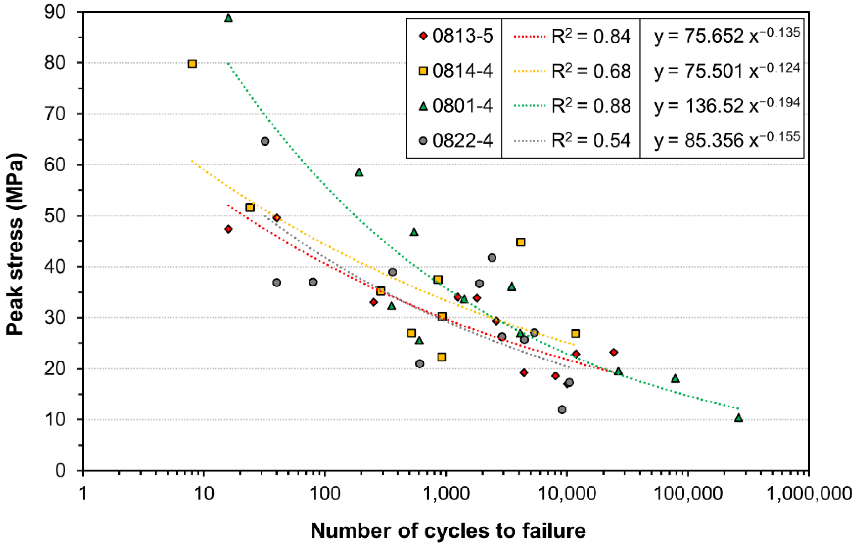
| Tissue ID | 0813-5 (n = 11) | 0814-4 (n = 9) | 0801-4 (n = 11) | 0822-4 (n = 12) | Combined (n = 50 *) |
|---|---|---|---|---|---|
| Cross-sectional area (mm2) | 13.42 ± 4.21 | 9.85 ± 2.09 | 11.16 ± 4.72 | 13.22 ± 4.69 | 12.04 ± 4.40 |
| Peak axial force (N) (min–max) | 250–510 | 250–500 | 200–500 | 240–500 | 200–510 |
| Peak stress (MPa) (min–max) | 17.08–49.59 | 22.31–79.79 | 10.45–88.86 | 11.99–64.66 | 10.45–88.86 |
| Number of cycles (min–max) | 16–24,364 | 8–11,744 | 16–261,784 | 32–10,476 | 8–261,784 |
| Coefficient of determination R2 | 0.84 | 0.68 | 0.88 | 0.54 | 0.65 |
Publisher’s Note: MDPI stays neutral with regard to jurisdictional claims in published maps and institutional affiliations. |
© 2022 by the authors. Licensee MDPI, Basel, Switzerland. This article is an open access article distributed under the terms and conditions of the Creative Commons Attribution (CC BY) license (https://creativecommons.org/licenses/by/4.0/).
Share and Cite
Scholze, M.; Safavi, S.; Ramezani, M.; Ondruschka, B.; Hammer, N. Fatigue Testing of Human Flexor Tendons Using a Customized 3D-Printed Clamping System. Appl. Sci. 2022, 12, 7836. https://doi.org/10.3390/app12157836
Scholze M, Safavi S, Ramezani M, Ondruschka B, Hammer N. Fatigue Testing of Human Flexor Tendons Using a Customized 3D-Printed Clamping System. Applied Sciences. 2022; 12(15):7836. https://doi.org/10.3390/app12157836
Chicago/Turabian StyleScholze, Mario, Sarah Safavi, Maziar Ramezani, Benjamin Ondruschka, and Niels Hammer. 2022. "Fatigue Testing of Human Flexor Tendons Using a Customized 3D-Printed Clamping System" Applied Sciences 12, no. 15: 7836. https://doi.org/10.3390/app12157836
APA StyleScholze, M., Safavi, S., Ramezani, M., Ondruschka, B., & Hammer, N. (2022). Fatigue Testing of Human Flexor Tendons Using a Customized 3D-Printed Clamping System. Applied Sciences, 12(15), 7836. https://doi.org/10.3390/app12157836