Abstract
The paper is focused on magnetorheological (MR) clutches applied in industrial drive systems working in a steady continuous-duty state. The main goal of the carried out numerical and analytical analyses oriented towards electrical power consumption, copper losses (Joule heat) in an excitation coil, spatial temperature distributions and the highest temperature possible for an MR fluid is to compare MR clutches due to a different number of discs. The authors considered selected representative MR multi-disc clutches with one, two, three or four discs, developing clutching torque equal to 20, 35 and 50 Nm. These clutches were constructed based on the in-house design that integrates analytical and field methods (further in the paper referred to as the integrated analytical-field design method) described in the literature. The thermal computer simulation results obtained with the help of the AGROS2D program, combined with findings achieved with the use of simplified physical reasonings, allow one to draw the conclusion that the most advantageous, recommended number of discs for a magnetorheological clutch from the viewpoint of various (both constructional and thermal) criteria is the number of discs: N = 2. This conclusion takes into account the results presented earlier in the literature: the choice is a compromise between decreasing the mass (volume) of the MR clutches and increasing both the electrical power consumption and the maximum temperature of MR fluids in a clutch working region as the number of discs, N, increases.
1. Introduction
Recently, there has been a systematic increase in interest in the use of magnetorheological (MR) fluids with viscosity controlled by magnetic or electric signals; these fluids can be found in a wide variety of devices (e.g., robots [1], testing stands [2], lifts [3] and two DoF brakes for investigating linear-rotary motors [4]) and seem to be particularly useful in automotive and motorcycle drive systems such as brakes and clutches [5,6]. In cars and motorcycles, there is a need for the frequent coupling and decoupling of internal combustion or electric drive motors with a vehicle’s wheel-drive system, and during such transient states, the clutches operate with varying slips, which result in friction (MR fluid–solid bodies), slip heat generation and, in consequence, temperature increases in the MR fluids having a direct influence on the clutch life. In recent years, this problem has been widely discussed by many authors [6,7,8,9]. A power flow diagram for MR clutches in transient states (acting with slippage) is depicted in Figure 1a,b.
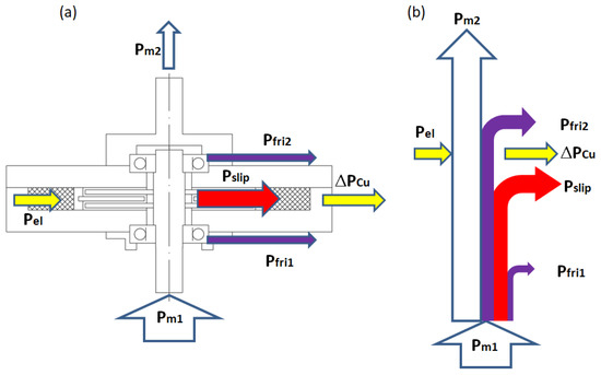
Figure 1.
Cross-section of multi-disc MR clutch: (a) mechanical and electrical sources of heat and (b) power flow diagram in transient states or in steady state with slippage where —input mechanical power; —output mechanical power; —input active electrical power; —slip power (related to slip heat generated in MR fluid in transient states); —copper losses (Joule heat); —mechanical power losses in bearings of driving member; —mechanical power losses in bearings of primary (driving) member.
Magnetorheological (MR) clutches can also be used in industrial drive systems because of the ease of the coupling and decoupling process and the possibility of acting as an overload protection system [5]. Industrial drive systems work for long periods in a steady continuous-duty state with no slippage; hence, the generation of heat in the MR fluid associated with transient states does not play a significant role. In such cases electrical power consumption necessary for the production of a magnetic field and maintenance of a coupling state becomes the key issue for MR clutches. Electric power in an excitation coil connected to the flow of the excitation current is released in the form of Joule heat and becomes—next to the heat sources associated with friction in bearings—an additional heat source, increasing the temperature of the working clutch.
For MR devices with a disc structure, commonly met in clutches, the possibility of a different number of discs is indicated, and each number of discs is associated with different properties.
In article [10], the authors considered in detail the problem of the optimal selection of the number of discs N in MR clutches (N is equal to the number of discs of a clutch primary (driving) member) in the industrial drive systems from the viewpoint of various criteria and limitations. In particular, the authors not only took into account the external dimensions of the clutches: their lengths and diameters, masses and volumes but also characteristic factors: the maximum torque per mass ratio and the maximum torque per volume ratio . The result of a detailed comparative analysis was the conclusion that the optimal (recommended) number of discs in a multi-disc magnetorheological clutch, taking into account the above-mentioned criteria, is equal to N = 2. In drawing this conclusion, the authors did not take into account the thermal operating conditions of the clutches. To their knowledge, in the available technical literature, the problem of power consumption by magnetorheological clutches in a steady continuous-duty states with no slippage, as well as copper losses in the excitation coil and spatial temperature distribution in such clutches (particularly, the maximum values of coils and MR fluid temperatures), has not been considered thus far. Hence, the main goal of this article is to consider the above-mentioned problems for MR clutches applied in the industrial continuous-duty drive systems.
The main view of an exemplary multi-disc MR clutch is depicted in Figure 2. This is the simplest case of a multi-disc MR clutch: the clutch having only two discs of a primary member (N = 2). The number of discs of a secondary member is equal to (N − 1).
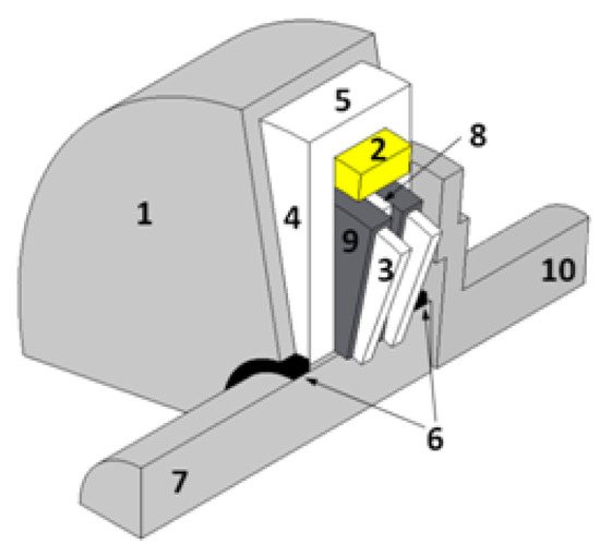
Figure 2.
Exemplary two-disc MR clutch (N = 2)—general view and basic terminology.
Owing to its symmetry, it is sufficient to present only a quarter of the entire construction.
Numbers 1, 2, 3, …, 10 indicate the most important constructional parts: 1—non-magnetic housing; 2—coil; 3—discs of a primary member; 4—cover yoke; 5—cylinder yoke; 6—bearings; 7—non-magnetic shaft of a primary member; 8—discs of a secondary member; 9—MR fluid gaps; 10—non-magnetic shaft of a secondary member. Particular care must be taken to prevent the leakage of magnetorheological fluids in the coupling. It is necessary to use an appropriate sealing system, the selection of which is dictated by the operating conditions.
2. Materials and Methods
2.1. Electromagnetic Analysis
In [11,12] the experimentally verified integrated analytical-field design method of multi-disc magnetorheological (MR) clutches was described in detail. Using this method, 12 variants of MR clutches, differing in the number of discs N and the values of the rated clutching torque were designed and their various features and properties essential from the viewpoint of manufacturing costs and industrial applications were compared in [10]. To render this comparison fully reliable and meaningful from a technical point of view, a number of assumptions were made, the most important of which were the following:
- The thickness of the MR fluid gap g is the same ( mm);
- Discs, cylinder yokes and cover yokes are made of the same magnetic steel;
- Shaft and mounting rings, separating the coil from the working region, are made of the same non-magnetic steel;
- Current density is assumed the same ( = 4.5 A/mm2) [13];
- Excitation current I is assumed the same ( 0.6 A);
- The magnetic flux density in MR fluid-gaps is kept the same despite variations in the geometries of clutches (.7 T);
- The maximum magnetic field density is kept the same (.2 T) despite variations in the geometries of clutches (the most saturated point lies within the cover yoke at a length approximately equal to the external radius of primary member discs).
As mentioned earlier, the designed clutches were compared in terms of the following criteria: overall dimensions, geometric proportions (lengths and radii of clutches), total masses m and total volumes V and factors including clutching torque per mass ratio and clutching torque per volume ratio . The conclusion resulting from this comparison, taking into account the costs of active materials on the one hand and the complexity of the manufacturing process on the other hand, was the statement that the optimal, recommended number of discs is N = 2.
This paper, as a logical continuation of the previously presented considerations, compares exactly the same variants of MR clutches with regards to the electrical power consumption necessary to maintain the coupling state, as well as spatial temperature distribution caused by copper losses in the excitation coil with resistance .
The electrical power consumption, , equal to copper losses caused by the flow of excitation current, I (Joule effect), is determined by the following formula:
where —copper resistivity; l—wire length needed to wind the coil; —diameter of the bare conductor; —cross-section of the bare conductor.
Due to the fact that the assumption of the same current density in the excitation coils of various variants is made, the cross-section of the conductor is the same for all considered cases. The values of the resistances for all point variants are, therefore, determined by the lengths of the wire l needed to wind the coils. This length is equal to the sum of the lengths of the individual turns, and these turns have different lengths depending on which coil layer they belong to (Figure 3). The geometrical cross-sections of all point variants (N = 1, 2, 3, 4 discs and 20, 35, 50 Nm (12 various variants)) have been presented graphically in [10] in a combined drawing, and this drawing is shown in this paper as Figure 4 with a variant numbering from V1 to V12.
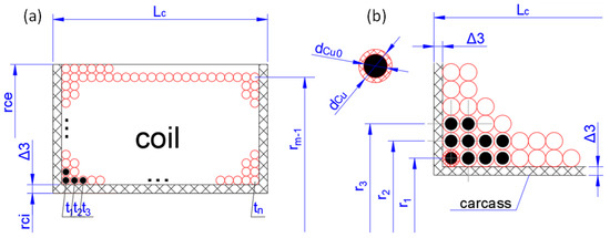
Figure 3.
The cross-section of clutch coil: (a) dimensions of coil and (b) dimensions of conductors.
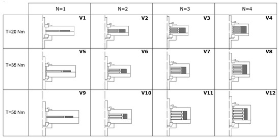
Figure 4.
Graphical overview of clutch cross-sections for all 12 designed variants: 20, 35, 50 Nm, N = 1, 2, 3, 4.
Let us now focus on the geometrical dimensions of the clutch elements and the winding data, the knowledge of which is necessary to determine the resistances of the individual coils. Letter markings of the clutch geometric dimensions and winding data (the number of coil turns z, the number of turns per one layer n and the number of layers m), necessary for determining the resistance of the coils, are shown in Figure 3 [10] on the example of an MR clutch with the number of discs: N = 2.
The design dimensions common for all the considered variants include the following: , , , and (Figure 3). The design dimensions, which are different for individual variants and depend on the rated values of the clutching torque, , and the number of discs, N, are summarized in Table 1 (these values were determined on the basis of the integrated analytical-field design method described in [10,12]).

Table 1.
List of design geometrical dimensions and winding data different for 12 individual variants.
The formulas for the lengths of the wires needed to wind the coils differ depending on whether the last layer is full; i.e., whether the condition
is fulfilled (Figure 3a) or whether the last layer is incomplete (Figure 3b), and there is a mathematical inequality.
If the condition (4) is met, we have the following:
where denotes the internal radius of the coil, denotes the thickness of the carcass and denotes the diameter of the insulated conductor.
If condition (5) is fulfilled, then another formula should be used:
where the number of turns in the incomplete m-th layer is .
Formulas (1)–(3), (6) and (7) allow the resistance of the excitation windings coils to be determined in an accurate manner as the sum of the resistances of the turns of the individual layers.
When designing transformers and electrical machines, we very often use simplified formulas, based on the concept of the average turn length , calculated on the basis of the overall dimensions of the coil, i.e., inner radius of the coil and outer radius of the coil .
Using the above relation, the formula for the coil resistance excitation winding resistance can be greatly simplified. In Table 2, the coil resistances and the electrical power consumption determined on the basis of exact Formulas (6) and (7) as well as their approximate values determined on the basis of simplified Formula (8) are listed.
Table 2.
Coil resistances and electrical power consumption for variants V1–V12 (exact values: , and approximate values determined on the basis of simplified formulas ( and )).
As observed, the approximate values calculated on the basis of the simplified formulas differ from the values by a maximum of 3.9%.
Exact values of coil resistance and electrical power consumption vs. the number of discs N are presented graphically in Figure 5.
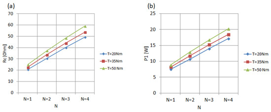
Figure 5.
(a) Values of coil resistance and (b) electrical power consumption vs. number of discs N.
The curves presented in Figure 6 and Figure 7 allow for a physical interpretation of the results obtained. The graphs for 20, 35 and 50 Nm in Figure 6a show that the number of turns z needed to a develop magnetic field in the MR fluid gaps with the average value (it should be remembered that the excitation current in all variants is the same and equals A) increases rapidly with the number of discs N and the number of fluid gaps 2 N and is practically independent of the values of clutching torque (notice that the three curves in Figure 6a coincide).
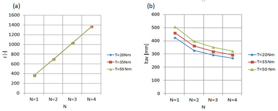
Figure 6.
(a) Number of turns z and (b) average length of the turns for individual excitation coils.
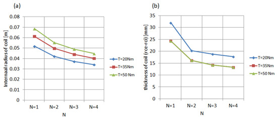
Figure 7.
Drop in internal radius of excitation coil and in its thickness: (a) internal radius of excitation coil vs. number of discs N; (b) thickness of excitation coil () vs. number of discs N.
The graphs for 20, 35 and 50 Nm in Figure 6b show that as the number of discs increases, the average length of the turns of the individual coils drops, which is due to the fact that the internal diameter of the coil decreases (see Figure 7a, presenting for 20, 35 and 50 Nm) and, moreover, that the coil becomes increasingly slender (see Figure 7b, presenting the thickness of the coil for 20, 35 and 50 Nm).
Obviously, the rapid increase in the number of turns together with the increasing number of discs is of decisive importance and the average length of the turns (decreasing as the number of discs increases) is not able to compensate for the effects of such a rapid increase in the number of turns, the consequence of which is an increase in the resistances of the excitation windings and the electrical power consumption.
Commenting finally on the results contained in Table 2 and shown graphically in Figure 5, it should be emphasized that the disadvantageous effect of a greater number of discs is an increase in the resistance values of the excitation coils, as well as an increase in clutch electrical energy consumption. The increase in copper losses is the reason why it is necessary to analyse the thermal state of clutches later in this article and to determine the influence of copper losses on the spatial temperature distributions in all the considered variants.
2.2. Thermal Analysis
The rapid increase in the electrical power consumed by the MR clutch (equal to copper losses) with the increased number of discs is the reason why the recommendation for the correct selection of the optimal variant of the device must take into account thermal calculations and the determination of the maximum operating temperature in a steady state. The maximum operating temperature of the clutch working region is important for the assessment of the clutch life, because high temperature may accelerate the aging of the magnetorheological fluid and even-after exceeding the permissible temperature can lead to the degradation of its properties [14].
Heat calculations are carried out according to the power flow diagram presented in Figure 8b. The only heat source taken into account is copper loss: the excitation winding is located in the immediate vicinity of the working region containing the MR fluid; hence, the loss in copper most strongly affects its fluid temperature. Thermal field simulations in a steady state were performed for all 12 variants V1–V12 in the AGROS2D program [15] (computer program in which magnetic calculations were previously carried out). Table 3 summarized values of the coefficients related to the heating process for the materials used in the clutch construction and for the air. It is worth reminding that the discs of primary and secondary members, cylinder yokes and cover yokes are made of magnetic steel and the shaft, bearings and housing are made of non-magnetic steel.
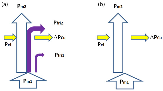
Figure 8.
Power-flow diagram (a) in steady continuous-duty state with no slippage: (b) case study considered in the paper (mechanical losses and are neglected; heat is transferred mainly to surrounding air and because of that it slightly influences temperature in clutch working regions including MR fluid).
Table 3.
Thermal coefficients for constructional materials and air (where —thermal expansion coefficient; —thermal conductivity; —heat convection coefficient; c—heat capacity; —mass density).
The results of the thermal calculations in the form of spatial temperature distributions for selected representative variants V1, V4, V9 and V12 are presented in Figure 9.
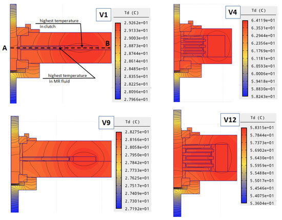
Figure 9.
Spatial temperature distribution in steady state for selected representative variants: V1, V4, V9 and V12.
The next Figure 10 shows an exemplary temperature drop along the axis AB which runs through the point with the highest temperature in the clutch (center of the coil) and through the point with the highest temperature in working region . This is the highest temperature possible for the MR fluid.
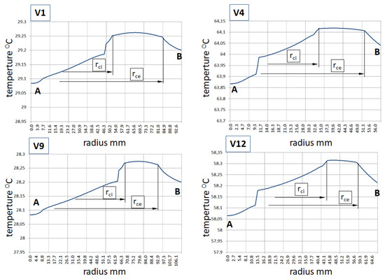
Figure 10.
Temperature drop along axis AB in a steady state for selected representative variants: V1, V4, V9 and V12.
The temperature drop for the considered 12 cases V1–V12 along the axis AB in a steady state is about – K. Maximum temperatures in the working region for all the 12 considered cases are shown in Figure 11.
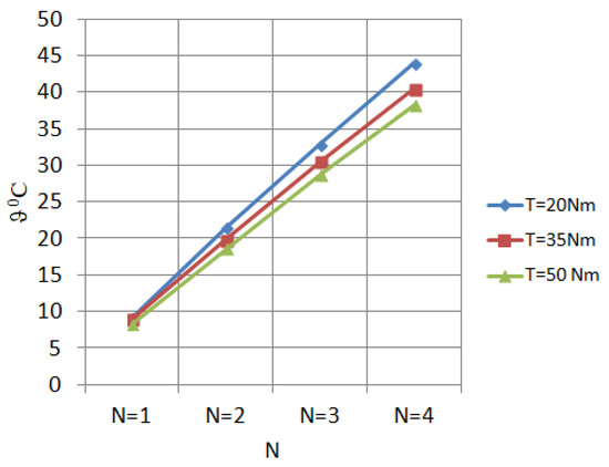
Figure 11.
Maximum temperature in the working region (the highest possible temperature for MR fluid) vs. the number of discs N for 20, 35 and 50 Nm).
As predicted, we can conclude that the greater the number of discs, the higher the maximum temperature, which is directly evidenced by Figure 5b, showing a substantial increase in copper losses as the number of discs increases.
It needs an explanation as to why, with the same number of discs, the higher maximum temperature is associated with the lower torque clutches and not with the higher torque clutches (related to higher copper losses). The explanation can be based on simplified approximate reasoning from the description of the process of heating a homogeneous body treated as a source of heat that transfers the accumulated heat by convection through the surface of to the surrounding air:
where —thermal conductivity; —heat convection coefficient; c—heat capacity; m—mass; —heat transfer area. The steady-state maximum temperature of such a homogeneous body as is described by the following formula:
where °C (293.15 K) is the temperature of the surrounding air.
In the case of the considered magnetorheological clutches, the area marked in Figure 12 can be considered as the surface of heat transfers to the environment:
where —internal radius of the coil; —external radius of the coil; —external radius of the bearings coupling; —cylindrical and cover yoke thickness.
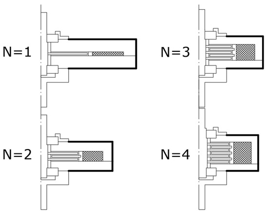
Figure 12.
The surface of heat transfer to the environment (surrounding air).
It is the outer area of the cylindrical yoke and 2 outer areas of the cover yokes. How they are changed with the increasing number of discs and increasing clutching torque is shown in Figure 13a,b.
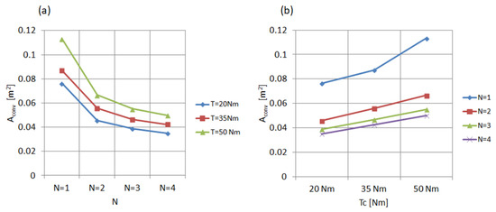
Figure 13.
Heat convection areas: (a) areas vs. number of discs N for 20, 35 and 50 Nm; (b) areas vs. clutching torque for the number of discs N = 1, 2, 3, 4.
As observed in Figure 13a, the area decreases for all variants with the increase in the number of discs, but with a fixed number of discs (Figure 13b), the area for a higher torque clutch is larger than that for a lower torque clutch.
This clearly explains the problem posed at the beginning of the discussion: why, with the same number of discs, the maximum temperature of the higher-powered clutches is lower.
This is evidently confirmed by Figure 14a, showing the course of the ratio (see Equation (10)) as a function of the number of discs for clutches of different torques and which set of functions has the same form as the set of functions characterizing the maximum value of the MR fluid temperature shown again for direct comparison in Figure 14b.
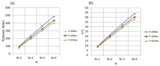
Figure 14.
Comparison of function courses: (a) the course of ratio vs. the number of discs for 20, 35 and 50 Nm; (b) maximum temperature vs. number of discs N for 20, 35 and 50 Nm.
Even better, the compliance of the curves describing the maximum temperature, T, with the curves presenting the ratio can be seen in the 3D charts (Figure 15).
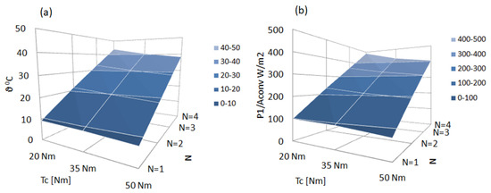
Figure 15.
Three-dimensional charts: (a) maximum temperature vs. clutching torque and number of discs; (b) ratio ratio vs. clutching torque and the number of discs.
The above-presented results of the thermal analysis allow one to confirm the conclusion given in [10,12] that the optimal recommended number of discs is equal to N = 2 and that it is a compromise option not only due to the values of characteristic factors (torque per mass ratio and torque per volume ratio) but also due to heat conditions. The operating temperature of the magnetorheological fluid is up to 130 °C [16]. Above this temperature, the properties of the liquid degrade and the magnetic properties are lost.
3. Results
The MR multi-disc clutches for industrial drive systems working in a steady continuous-duty state were compared from the viewpoint of electrical energy consumption and temperature spatial distribution. The electric power consumption , excitation coil resistance , power copper losses , spatial temperature distributions and the maximum temperature of the magnetorheological fluid were determined for twelve representative variants on the basis of field numerical calculations. It was explained in detail, in physical terms, why as the number of discs increases, the maximum temperature of the magnetorheological fluid increases too and also why, for the same number of discs in higher torque clutches, the temperature of the magnetorheological fluid is slightly lower than in smaller torque clutches. The general conclusion presented is that the most advantageous, recommended number of discs for a magnetorheological clutch from the viewpoint of electric, magnetic, mechanical and thermal criteria is the number of discs, N = 2. This conclusion takes into account the results of the analysis performed in an earlier article [10]: the choice is a compromise between the decreasing mass (volume) of the MR clutches and increasing both electrical power consumption and the maximum temperature of the MR fluid in the clutch working region as the number of discs N increases.
The authors focused on a steady continuous-duty state of industrial drive systems. The next step will be to use the presented approach based on computer field simulations combined with simplified physical reasoning to analyse transient thermal states and steady-states during slippage.
Author Contributions
Conceptualization, K.K. and Z.P.; methodology, K.K.; software, Z.P.; validation, Z.P. and K.K.; formal analysis, Z.P. and K.K.; writing—original draft preparation, Z.P.; writing—review and editing, Z.P.; visualization, Z.P.; supervision, K.K. All authors have read and agreed to the published version of the manuscript.
Funding
This research was conducted at the Faculty of Electrical and Computer Engineering, Cracow University of Technology. Funded by research funds for 2022.
Institutional Review Board Statement
Not applicable.
Informed Consent Statement
Not applicable.
Data Availability Statement
Not applicable.
Conflicts of Interest
The authors declare no conflict of interest. The funders had no role in the design of the study; in the collection, analyses, or interpretation of data; in the writing of the manuscript; or in the decision to publish the results.
Abbreviations
The following abbreviations are used in this manuscript:
| MR clutches | Magnetorheological clutches |
References
- Pisetskiy, S.; Kermani, M.R. A Concept of a Miniaturized MR Clutch Utilizing MR Fluid in Squeeze Mode. In Proceedings of the IEEE/RSJ International Conference on Intelligent Robots and Systems (IROS), Las Vegas, NV, USA, 24 October 2020–24 January 2021; pp. 6347–6352. [Google Scholar]
- Xiong, H.; Luo, Y.; Ji, D.; Ren, H.; Weid, D.; Liu, W. Analysis and evaluation of temperature field and experiment for magnetorheological fluid testing devices. Adv. Mech. Eng. 2021, 13. [Google Scholar] [CrossRef]
- Piech, Z., IV; Szeląg, W. Elevator Brake with Magneto-Rheological Fluid. US Patent US 8,631,917 B2, 21 January 2014. [Google Scholar]
- Kowol, P. Hamulce Magnetoreologiczne o Jednym i Dwóch Stopniach Swobody. (Magnetorheological Brakes with 1 or 2 DoF). Ph.D. Thesis, Silesian University of Technology, Gliwice, Poland, 2007. (In Polish). [Google Scholar]
- East, W.; Turcotte, J.; Plante, J.; Julio, G. Experimental assessment of a linear actuator driven by magnetorheological clutches for automotive active suspensions. J. Intell. Mater. Syst. Struct. 2021, 32, 955–970. [Google Scholar] [CrossRef] [PubMed]
- Wang, D.; Zi, B.; Zeng, Y.; Xie, F.; Hou, Y. An investigation of thermal characteristics of a liquid-cooled magnetorheological fluid-based clutch. Smart Mater. Struct. 2015, 24, 055020. [Google Scholar] [CrossRef]
- Rahul, R.; Pugazhenthi, R.; Eugene, J.; Antony, A.; Viswanath, B. Mathematical Modelling of Temperature Rise in Clutch and Design, Analysis and Fabrication of Cooling System for Clutch. Int. J. Sci. Eng. Res. 2015, 6, 603–611. [Google Scholar]
- Agyeman, P.K.; Tan, G.; Alex, F.J.; Peng, D.; Valiev, J.; Tang, J. Mathematical The study on thermal management of magnetorheological fluid retarder with thermoelectric cooling module. Case Stud. Therm. Eng. 2021, 28, 101686. [Google Scholar] [CrossRef]
- Jędryczka, C.; Szeląg, W.; Myszkowski, A. Model of coupled electromagnetic, hydrodynamic, thermal and mechanical motion phenomena in axial symmetry magnetorheological fluid torque transducer. Electr. Rev. 2010, R86, 195–200. (In Polish) [Google Scholar]
- Kluszczyński, K.; Pilch, Z. The Choice of the Optimal Number of Discs in an MR Clutch from the Viewpoint of Different Criteria and Constraints. Energies 2021, 14, 6888. [Google Scholar] [CrossRef]
- Kowol, P.; Pilch, Z. Analysis of the magnetorheological clutch working at full slip state. Electr. Rev. 2015, 1, 110–113. [Google Scholar] [CrossRef][Green Version]
- Kluszczyński, K.; Pilch, Z. Integrated analytical-field design method of multi-disc magnetorheological clutches for automotive applications. Bull. Pol. Acad. Sci. Tech. Sci. 2021, 69. [Google Scholar]
- Standard Specification for Standard Nominal Diameters and Cross-Sectional Areas of AWG Sizes of Solid Round Wires Used as Electrical Conductors. ASTM International. 2014. Available online: http://www.astm.org/Standards/B258.htm (accessed on 3 July 2022).
- Pilch, Z. Analysis of Established Thermal Conditions for Magnetorheological Clutch for Different Loading Conditions. In Analysis and Simulation of Electrical and Computer Systems; Springer International Publishing: Berlin/Heidelberg, Germany, 2015; pp. 197–213. [Google Scholar]
- Available online: http://www.agros2d.org/ (accessed on 6 June 2022).
- MRF-140CGMRFluid. Available online: https://lordfulfillment.com (accessed on 3 July 2022).


Publisher’s Note: MDPI stays neutral with regard to jurisdictional claims in published maps and institutional affiliations. |
© 2022 by the authors. Licensee MDPI, Basel, Switzerland. This article is an open access article distributed under the terms and conditions of the Creative Commons Attribution (CC BY) license (https://creativecommons.org/licenses/by/4.0/).