Article

Numerical Study on the Pressure Relief Characteristics of a Large-Diameter Borehole

1
College of Energy Engineering, Xi’an University of Science and Technology, Xi’an 710054, China
2
Key Laboratory of Western Mines and Hazard Prevention of China Ministry of Education, Xi’an 710054, China
3
Key Laboratory of Coal Resources Exploration and Comprehensive Utilization of Ministry of Land and Resources, Xi’an 710021, China
4
Xinjiang Energy Co., Ltd., National Energy Group, Urumqi 830027, China
*
Author to whom correspondence should be addressed.
Appl. Sci. 2022, 12(16), 7967; https://doi.org/10.3390/app12167967
Submission received: 20 July 2022 / Revised: 4 August 2022 / Accepted: 8 August 2022 / Published: 9 August 2022
(This article belongs to the Special Issue Mechanics, Damage Properties and Impacts of Coal Mining)

Abstract

:
Large-diameter drilling is an effective method for preventing rock burst disasters in coal mines. In this paper, the roadway stability of the W1123 fully mechanized caving work face of the Kuangou coal mine, located in northwest China, is investigated. A set of numerical modelling techniques were carried out to study the characteristics of stress, displacement, strain energy and the plastic zone of the roadway side rock with different parameters, including the large-diameter drilling hole diameter, depth and spacing. The results showed that: (1) after drilling, the peak values of the stress and strain energy are reduced and transferred to a deeper location, and the control effect presents a positive correlation with the diameter of the drilling hole; (2) when Lh < LP, there are no pressure relief and energy release effects, which may induce impact, whereas when LP < Lh ≤ 2.5LP, with the increase of the hole depth, the effects of pressure relief and energy release are enhanced, and further extension is not conducive to the long-term stability of the roadway; and (3) when the hole spacing decreases, the plastic zone and the broken zone between the holes are gradually penetrated, and the stress pattern transforms from a double peak to a saddle shape and then to single peak. Reducing the hole diameter reduces the efficiency of the plastic zone, failure zone and the stress form transformation between the boreholes, and weakens the pressure relief effect. Therefore, the main factor affecting the pressure relief effect is the hole diameter, and the secondary factor is the hole spacing. The engineering practice employed here showcases how a larger-diameter hole is an effective way of enhancing the effect of pressure relief and controlling the occurrence of rock burst. These research results are of great significance for guiding engineering practice.

1. Introduction

Rock burst is one of the serious disasters in coal mining, and it often occurs in hard rock, which does not easily produce microcracks and is not easily gradually destroyed. Under the conditions of high ground stress and mining disturbance, it is easy to accumulate high energy. When the energy accumulation exceeds the minimum energy of impact damage, the high energy accumulated in the rock is released instantly, causing the rock to disintegrate instantly, forming rock burst [1,2,3,4]. By 2021, more than 200 mines in China had experienced rock burst, which is sudden and destructive and seriously threatens the lives of underground workers. Therefore, the prevention and control of rock burst is the top priority in the safe mining of deep mines. Many scholars, nationally and abroad, have conducted a great deal of research on the disaster mechanism of rock burst and achieved fruitful results [5,6,7,8,9,10]. Based on the study of this disaster mechanism, the prevention and control countermeasures of rock burst have been put forward. Some scholars developed a better method for supporting the roadway for rock burst mines, which minimizes the damage of rock burst to the roadway [11,12]. In addition, some scholars reduced the stress concentration, energy accumulation and impact risk by studying the reasonable advancing speed [13]. The key to the prevention and control of rock burst is to weaken the high stress and release the elastic energy accumulated in the coal and rock mass. The methods of pressure relief in the roadway include blasting, water injection, slotting, drilling, and so on. Among them, the borehole has the characteristics of minimal engineering quantity, simple and convenient operation, simple construction and little disturbance to the coal and rock mass, and it does not affect normal mining activities; thus, it has strong economic benefits as a measure for preventing rock burst in coal mines [14,15,16,17,18].
Many scholars have made advances in research on borehole pressure relief. Hao et al. verified the pressure relief effect of nonequal-diameter holes through numerical simulations performed in FLAC3D [19]. Liang et al. carried out a numerical study that indicated that a larger borehole diameter can result in a better stress relief effect [20]. Ji et al. proposed an analytical model for the hard roof over the coal seam that suggests that the increase of the pressure relief distance is a better method than the increase of the pressure relief degree in reducing the abutment stress [21]. Zhang et al. suggested an evaluation method using six parameters to evaluate the stress relief effect of large-diameter drilling [22]. Gu et al., based on the theory of elastoplastic mechanics, conducted an analysis of the stress distribution around the borehole and studied the mechanism of pressure relief in segmented enlarged-diameter boreholes [23]. Peng et al. carried out a set of case studies with different borehole layout strategies that resulted in different AE characteristics, as well as strength reduction and rock failure patterns [24]. Zhai et al. suggested that the higher the stress on the surrounding rock is, the larger the diameter of the drilling hole will be, and the more cuttings will be produced by the drilling hole; thus, a large-diameter borehole can effectively prevent rock burst and relieve pressure [25]. He et al. carried out a red sandstone experiment on rock burst with different drilling numbers and arrangement modes, using the peak-strength strain energy storage index to describe quantitatively the failure strength characteristics of the specimen [26]. Li et al.’s study results show that the larger the size of the pressure relief boreholes is, the better the pressure relief effect will be, and the greater the disturbance to the coal seam will be; thus, an oversized pressure relief borehole may induce rock burst, and borehole spacing is of critical importance [27]. Wang et al., by improving the strain-softening model in FLAC3D by a secondary development, proposed the assessment index for the effectiveness of borehole destressing and the classification criteria for the destressing degree [28]. Wang et al.’s study results show that the borehole pressure relief reduces the accumulated strain energy before the peak and reduces the energy release per unit time after the peak, making the sample less prone to dynamic damage [29]. However, there is relatively little research on the primary and secondary relationships between the key parameters of borehole pressure relief, and on directions for the optimization and adjustment of parameters.
In this paper, taking the coal pillar of W1123, a fully mechanized caving face in the B2 coal seam of Kuangou coal mine, as the research background, we use numerical simulations to study the influences of the key parameters, such as hole diameter, hole depth and hole spacing, on the pressure relief characteristics, comprehensively analyzing the evolution laws of the stress, strain energy, displacement and plastic zone.

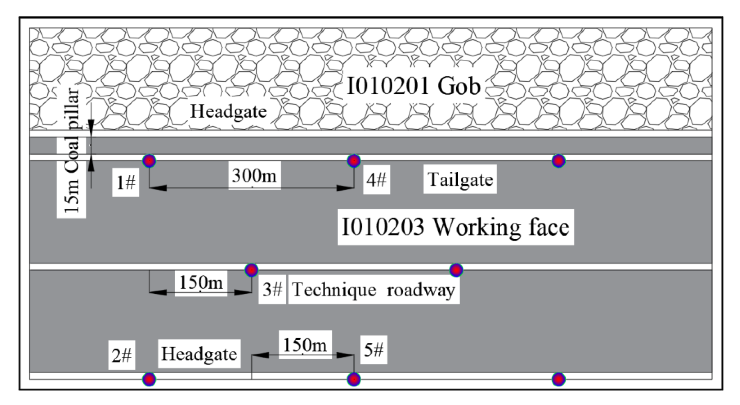
2. Engineering Background

Kuangou coal mine is located in Queergou Town, Hutubi County, Changji Prefecture, Xinjiang. The main coal seam is the B2 coal seam, now with the W1123 fully mechanized top-coal caving face, the stratigraphy of its geological basin as shown in Figure 1.
The W1123 fully mechanized top-coal caving face is arranged in the west wing of the No.1 mining area of the B2 coal seam, which is located at level 1255 of the mine. Its exploitable strike length is 1468 m, and its inclined length is 192 m. The designed mining height is 3.2 m, the coal caving thickness is 6.3 m, the mining–caving ratio is 1:1.97, and the average inclination angle of the working face is 14. The horizontal elevation of the transportation lane in the W1123 fully mechanized top-coal caving face section is +1321 m to +1327 m, the horizontal elevation of the return air lane in the section is +1365 m to +1375 m, and the elevation of the working face is +1660 m to +1820 m. At the horizontal elevation of +1343 m to +1346 m, the technical roadway is arranged. The main functions of the roadway are mine pressure prevention, gas prevention, and the air intake at the working face, with a length of 1469 m. On the working face, the upper 50 m of the 13 to 745 m section of the transportation lane connecting the lane to the west is the W1145 goaf of the B41 coal seam, and the lower 15 m of the same coal seam is the W1121 goaf. The lower part of the working face is the B1 solid coal seam. Figure 2 shows the layout plan of the working face roadway.
There is a risk of impact of the mining process on the working face; thus, it is necessary to drill a large-diameter hole to relieve the pressure of the roadway. This paper takes the transportation roadway of the W1123 fully mechanized top-coal caving face as its research object. The section of the roadway is arc-shaped, and the section size (width × height) is 4.7 m × 3.4 m. It is supported by a bolt (cable), anchor net, and steel belt.

3. Materials and Methods

3.1. Build Numerical Model

FLAC3D software can effectively simulate the stress and plasticity characteristics of materials such as rock and soil. Therefore, FLAC3D numerical simulation software was selected by the authors of this paper for simulating the influences of different drilling parameters on the pressure relief effect to achieve good simulation results.
After the excavation of the upper section of the W1123 working face in the B2 coal seam of Kuangou coal mine, the internal stress of the roadway side was redistributed, the peak value of the lateral abutment pressure of the roadway was increased, and the peak value of the stress was close to the coal wall; thus, it was easy to accumulate high energy and impact. Therefore, we obtained the established numerical model as shown in Figure 3, the model being 40 m in length, 12 m in width, and 32 m in height.
The vertical buried depth of the W1123 working face in the B2 coal seam is H = 400 m, and the vertical stress s basically equal to the weight of overlying strata. After measuring the average bulk density of rock mass γ = 2500 kg/m3, taking into account the mining influence and tectonic influence, the stress concentration coefficient was identified as 1.3, and the vertical stress on the B2 coal seam was σz = 1.3γH, calculated to obtain σz = 13 MPa, and the lateral pressure coefficient was λ = 0.8, calculated to obtain σx = σy = 0.8 σz = 10.4 MPa. The material parameters are shown in Table 1.
Because coal is an elastic-plastic material, the Mohr–Coulomb criterion for the ideal elastoplastic body is used to judge the deformation and failure of rock.
f s = σ 1 σ 3 1 + sin φ 1 sin φ 2 c 1 + sin φ 1 sin φ
In this formula, σ1 and σ3 are the maximum and minimum principal stress, respectively, c is the adhesive force, and φ is the friction angle. When fS > 0, the material will undergo shear failure and strain softening. Under normal stress conditions, the tensile strength of the rock mass is very low; thus, one can judge whether the rock mass has tensile failure according to the tensile strength criterion (σ3σT).

3.2. Experimental Scheme

3.2.1. Experimental Scheme of the Hole Diameter

We studied the influence of the drilling hole diameter on the pressure relief and energy release. The experimental scheme was designed as a single hole with a depth of 11 m and different hole diameters. At present, the maximum diameter of the mine drilling rig is 0.4 m; thus, the upper limit of the experiment is 0.4 m. Eight groups of experiments were designed, with the diameters of 0.05 m, 0.10 m, 0.15 m, 0.20 m, 0.25 m, 0.30 m, 0.35 m, and 0.40 m, respectively.

3.2.2. Experimental Scheme of the Hole Depth

To study the influence of the drilling hole depth on the pressure relief and energy release, a single hole with a diameter of 0.30 m and hole depths of 3 m, 5 m, 7 m, 9 m, 11 m, 13 m, and 15 m was designed.

3.2.3. Experimental Scheme of the Hole Spacing

We studied the influence of the hole spacing on the stress evolution, displacement, and plastic zone. Three groups of experimental schemes were designed, with a hole depth of 11 m and hole diameters of 0.3 m, 0.2 m, and 0.1 m, respectively. Four experimental schemes were designed for each hole diameter, the hole distances being 4 m, 3 m, 2 m, and 1 m, respectively.

4. Results

4.1. Effects of the Hole Diameter on the Pressure Relief Effect

4.1.1. Stress Evolution Law

The experimental results are shown in Figure 4. It can be seen from Figure 4a that, compared with the coal body on the side of the roadway without drilling, the coal body on the side of the drilling was basically not depressurized when the hole diameter was 0.05 m, and there was still a stress core in the coal body, and there was no pressure relief area around the drilling hole. When the hole diameter was 0.10 m to 0.40 m, the stress core in the coal body on the borehole side of the roadway disappeared, the range of the pressure relief area around the borehole gradually expanded, and the pressure relief effect gradually improved.
In Figure 4b, LP indicates the original stress peak position, LP1 indicates the shift position of the stress peak after drilling, and P0 is the original rock stress. It can be seen from Figure 4b that, after drilling, the stress peak value decreased and moved to the deep area. When the hole diameter was 0.05 m, the stress reduction was not obvious, and the pressure relief effect was poor. When the hole diameter was 0.10 m to 0.40 m, the stress in the coal body decreased uniformly with the increase in the hole diameter, and the pressure relief effect gradually improved.
The original rock stress in the deep part of the roadway was P0 = 15.62 MPa. The area where the internal stress in the borehole was less than the original rock stress was divided into the decompression area, and the ratio of the decompression area to hole length under different diameters was compared (A/Lh, where A is the decompression area and Lh is the borehole length).
As shown in Figure 5, this was 22.7% when the hole was not drilled and 18.2% when the hole diameter was 0.05 m, which is smaller than that when the hole diameter was 0.05 m, indicating that the range of the pressurized area was enlarged instead, and the pressure relief effect was poor. The hole diameter was 34.6% at 0.10 m, which is larger than that without drilling, and it was 81.8% at 0.15 m. The A/Lh value increased with the increase in the hole diameter, indicating that the larger the hole diameter was, the smaller the high stress range in the coal roadway body was. When the hole diameter was larger than 0.20 m, it was 100%, and the whole length of the borehole was a decompression zone. Increasing the hole diameter only reduced the stress value in the borehole range. This indicates that the pressure relief of the borehole was significant on this occasion, and the pressure relief effect was further enhanced with the increase in the hole diameter.

4.1.2. Strain Energy Density Evolution Law

From the strain energy density, the influence of the drilling hole diameter on the energy release effect was analyzed. The experimental results are shown in Figure 6. From Figure 6a, it can be seen that when the hole diameter was 0.05 m, the strain energy density of the coal body on the drilling side of the roadway was basically unchanged, the energy core still existed, and the accumulated energy in the coal body was not released. When the hole diameter was 0.10 m to 0.40 m, the energy core in the coal on the side of the borehole disappeared, and the energy−releasing area of the coal around the borehole gradually increased with the increase in the hole diameter. In Figure 6b, LP indicates the peak position of the original strain energy density, LP1 indicates the peak shift position of the strain energy density after drilling, and E0 indicates the strain energy density in the original rock area. It can be seen from Figure 6b that, after drilling, the peak value of the strain energy density decreased and moved to the deep area. When the hole diameter was 0.05 m, the strain energy density decreased a little, and the energy release effect was poor. When the hole diameter was 0.10 m to 0.40 m, the strain energy density in the coal decreased uniformly with the increase in the hole diameter, and the energy release effect gradually improved.
The strain energy density E0 = 37.32 KJ/m3 in the deep rock area of the roadway, with (EPE0)/E0 (where EP is the peak value of the strain energy density and E0 is the strain energy density in the original rock area), was used as the representative value of the energy release effect of the borehole. A positive value indicated energy accumulation and a negative value indicated energy release, as shown in Figure 7.
(EPE0)/E0 gradually decreased with the increase in the hole diameter, which indicates that the energy accumulation in the coal on the borehole side decreased with the increase in the hole diameter. When the hole diameter was D ≥ 0.20 m, (EPE0)/E0 < 0, there was no energy accumulation in the original rock area, which indicates that the elastic energy accumulation in the coal throughout the whole borehole length was small at this time. Increasing the hole diameter only led to the decrease in the strain energy density in the borehole range, which indicates that the energy release effect of the borehole was further enhanced with the increase in the hole diameter.
By analyzing the evolution law of stress and strain energy density under different diameters of the large-diameter borehole, it can be concluded that the peak values of stress and strain energy density, after drilling, decreased and moved to the deep area. With the increase in the borehole diameter, the stress concentration and strain energy density in borehole coal decreased, and the pressure relief area gradually increased. There was basically no pressure relief when the hole diameter was too small; thus, a reasonable hole diameter is 0.10 m~0.40 m, according to the actual situation (the mechanical properties of coal and rock, the diameter of existing drilling rig in the mine, etc.).

4.2. Effects of the Hole Depth on the Pressure Relief Effect

4.2.1. Stress Evolution Law

The evolution characteristics of the borehole stress at different hole depths are shown in Figure 8, and the LP represents the original stress peak position.
It can be seen from Figure 8a that the pressure was basically not released when the hole depth was 3 m, indicating that the borehole had not crossed the stress core in the coal body, so that the pressure could not be released. When the depth of the hole was 5 m, the stress core of the coal on the borehole side obviously decreased, and the pressure was relieved. When the hole depth was 5 m to 15 m, with the increase in the hole depth, the range of the pressure relief zone in coal body extended to the deep area, which indicates that the hole depth determines the pressure relief depth.
It can be seen from Figure 8b that, when the hole depth was 3 m, the stress peak did not move to the deep area, and the peak stress did not change, indicating that the hole depth was not great enough to transfer the stress peak to the deep area. When the depth of the hole was 5 m, the peak value moved to the deep area, and the stress of the borehole coal body decreased, which indicates that the peak value can move to the deep area only when the hole depth is greater than the peak value position, thus achieving the pressure relief effect. When the hole depth was 5 m to 11 m, the stress peak continuously moved to the deep area and decreased with the increase in the hole depth, which indicates that the increase in the hole depth not only extends the pressure relief range, but also further improves the pressure relief effect. When the hole depth was greater than 11 m (2.5LP), the peak stress basically remained unchanged, and the enhancement of the pressure relief effect through the hole depth reached its limit. If the hole depth were to be extended, this would only drive the depth of the pressure relief zone.

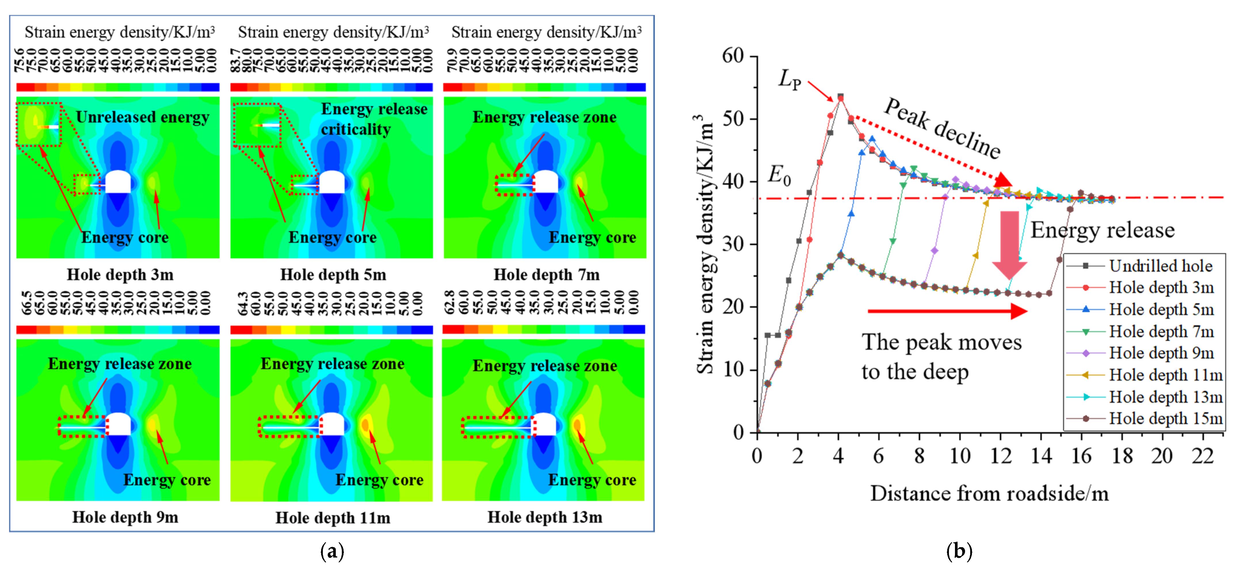
4.2.2. Strain Energy Density Evolution Law

The evolution law of strain energy density in the borehole coal under different hole depths is shown in Figure 9.
It can be seen from Figure 9a that, when the hole depth was 3 m, the energy core in the coal at the borehole side was still large, indicating that the borehole had not crossed the energy core and could not release the elastic energy. When the hole was 5 m deep, the energy core obviously decreased and the accumulated energy was released. The depth of the hole was 5 m to 13 m, and with the increase in the hole depth, the energy release area extended to the deep area, which indicates that the hole depth determines the depth of the energy release. It can be seen from Figure 9b that, when the hole depth was 3 m, the energy peak value did not move to the deep area, and the peak value did not decrease, indicating that the hole depth was not great enough to release the energy of the energy core. When the hole depth was 5 m, the peak energy moved to the deep area, and the accumulated energy in the drilled coal decreased, which indicates that the accumulated energy in the coal can be effectively released when the hole depth is greater than the peak value. When the hole depth was 5 m to 11 m, with the increase in the hole depth, the peak value continuously moved to the deep area and decreased, and the energy in the borehole coal body remained unchanged after decreasing to a certain value, which indicates that the increase in the hole depth not only extends the energy release range, but also further improves the energy release effect. When the hole depth was more than 11 m (2.5LP), the energy at the peak value basically remained unchanged, and the enhancement of the energy release effect through the hole depth reached its limit. Extending the hole depth will only extend the depth of the energy release zone.

4.2.3. Reasonable Hole Depth Analysis

By analyzing the evolution law of stress and strain energy density at different hole depths, the model of Figure 10 was established. As shown in Figure 10a, when LhLP, the peak stress and energy did not move to the deep area, and the peak stress and energy did not decrease. The peak stress and high energy were transmitted to the free surface, and a new free surface was formed at the end of the borehole, which was closer to the peak stress and the high energy than the roadway side. The transmission path of the peak stress and high energy to the free surface was shortened, and the impedance capacity of the surrounding rock before the peak was reduced, which can induce impact. As shown in Figure 10b, when LP < Lh ≤ 2.5LP, the stress and energy peaks extended to the deep area and decreased with the increase in the hole depth, so that the stress and energy of the borehole coal body decreased, reducing the danger of impact on the roadway side and forming a protective body.
As shown in Figure 10c, when the Lh > 2.5LP, the peak stress and energy were unchanged, and the enhancement of the pressure relief and energy release effect due to the hole depth reached its limit. Increasing the hole depth only leads the extension of the pressure relief and energy release area, and the stress readjustment time of the roadway after drilling is prolonged with the increase in the hole depth, which increases the time for the roadway to enter a steady creep and the deformation of the roadway, which is not conducive to the long-term stability of the roadway [30]. At the same time, for gas mines, therefore, the reasonable drilling range is determined as follows: LP < Lh ≤ 2.5LP.

4.3. Effects of the Hole Spacing on the Pressure Relief Effect

4.3.1. Displacement Evolution Law

The evolution law of displacement between the boreholes is shown in Figure 11. The green area is the area where the coal is broken, and the blue area is the area where the coal is not broken.
When the hole diameter was 0.3 m, with the decrease in the hole spacing, the undamaged area of coal among the boreholes gradually shrunk, and the damaged area ran through when the hole spacing was 2 m. When the hole spacing was 1 m, the damaged area of coal among the boreholes was completely connected, and the pressure relief was good. When the pore diameter was 0.2 m, it had the same evolution law, but the evolution efficiency was slower than that when the pore diameter was 0.3 m. When the hole diameter was 0.1 m, there was no close in the broken area of the coal body between the boreholes at 4 m, 3 m, and 2 m. When the hole distance was 1 m, the coal break shape between the holes was similar to that when the hole diameter was 0.3 m and the hole distance was 2 m, but there was no complete run through. This shows that the influence of the hole diameter on the damage of the borehole coal is greater than that of the hole spacing, and the hole diameter plays a leading role in the damage of the borehole coal, while the hole spacing plays a secondary role. Therefore, in order to achieve good pressure relief, the hole diameter should be increased as much as possible, so as to increase the hole spacing and reduce the amount of pressure relief at work.

4.3.2. Evolution Characteristics of the Plastic Zone

The evolution law of the plastic zone of the coal among the experimental boreholes is shown in Figure 12. It can be seen from the figure that, when the hole diameter was 0.3 m, the plastic zone was not closed when the hole spacing was 4 m, and there was a certain range of the elastic zone in the coal between the boreholes. When the hole spacing was 3 m, the plastic zone between the boreholes was still large, the plastic zone was not completely closed when the hole spacing was 2 m, the elastic zone between the boreholes was further reduced, and the plastic zone was completely closed when the hole spacing was 1 m. When the hole diameter was 0.2 m, the rule was the same. With the decrease in the hole spacing, the elastic zone between the holes shrunk, but the hole spacing was 2 m, not completely closed, and the plastic zone was closed when the hole spacing was 1 m. The same rule applied when the pore diameter was 0.1 m, but the connectivity efficiency of the plastic zone was obviously different from those of 0.3 m and 0.2 m, and the plastic zone was basically connected when the pore distance was 1 m. It can be seen that, the larger the hole diameter was, the larger the hole distance needed to be to close the plastic zone, and the efficiency of the closed plastic zone was higher and the effect was better.

4.3.3. Stress Evolution Law

It can be seen from Figure 13 that, after drilling, a pressure relief area appeared in the coal around the drilling hole. When the hole diameter was 0.3 m, and the hole spacings were 4 m and 3 m, the stress pattern in coal body between boreholes had a double peak shape. When the hole spacing was 2 m, the stress pattern was saddle shaped, and when the hole spacing was 1 m, the stress pattern was a single peak shape. When the hole diameter was 0.2 m, and the hole spacings were 4 m and 3 m, the stress pattern in coal body between boreholes was a double peak shape, and when the hole spacings were 2 m and 1 m, the stress pattern was saddle shaped, but the stress pattern was close to a single peak when the hole spacing was 1 m. When the hole diameter was 0.1 m, and the hole spacings were 4 m, 3 m, or 2 m, the stress pattern in the coal body between the boreholes was a double peak shape, and when the hole spacing was 1 m, the stress pattern was saddle shaped. Therefore, when the pressure relief is good, the stress pattern is a single peak. With the increase in the hole diameter and the decrease in the hole spacing, the transformation efficiency of the stress form between the holes increases, and the pressure relief effect improves.

4.3.4. Analysis of Reasonable Borehole Spacing

From the above analysis of the stress, displacement, and plastic zone evolution characteristics between the boreholes, it can be seen that the main factor affecting the borehole pressure relief is hole diameter, and the secondary factor is the hole spacing. In the case of a certain borehole diameter, the borehole spacing has a great influence on the pressure relief effect of the coal. If the borehole spacing is too large, the pressure relief area of the coal cannot be connected, and the pressure relief effect is poor. If the borehole spacing is too small, the engineering quantity is great, and the cost is high. Therefore, it is necessary to determine the reasonable drilling spacing.
In Figure 14, γ H   is the original rock stress, where K1 and K2 are the stress concentration factors and K2 > K1, D is the diameter of the borehole, X0 is the radius of the plastic zone (the distance between the stress peak and borehole center), X1 is the width of the elastic zone between two boreholes, LIn is the influence range of the borehole side stress, and LSP is the borehole spacing.
As shown in Figure 14a, when LSP ≥ 2LIn, the stress between boreholes showed a double peak shape, the coal between boreholes was not damaged, the plastic zone was not connected, the pressure relief effect was poor, and there was a risk of impact. As shown in Figure 14b, when 1.5LInLSP ≤ 2LIn, the stress between boreholes was saddle shaped, the coal between boreholes was still not damaged, the plastic zone was not connected, and the pressure relief effect was poor. With reference to the safety distance of the coal pillar in the roadway protection, the critical value of coal pillar safety is the width of the elastic core in the middle being 2 m (m is the mining height). However, pressure relief by drilling requires the man-made destruction of the rock mass; thus, the critical value of the coal mass destruction between drilling holes is 2D. Therefore, when LSP = LIn + 2D (as shown in Figure 14c), the coal between the boreholes was destroyed, the plastic zone was connected, and the pressure relief effect was good. When LSP = LIn, the stress between boreholes was a single peak, the plastic zones were connected, and the pressure relief effect was good. If the drilling spacing is reduced, the engineering quantity will increase, and the pressure relief cost will increase.
To sum up, it is necessary to artificially destroy the coal between the boreholes and close the plastic zone during the pressure relief of the boreholes. Therefore, it is determined that the pore size range of the borehole in order to achieve good pressure relief is:
LInLSPLIn + 2D
In this formula, LIn takes two times the radius of the plastic zone, namely LIn = 2X0, to get:
2X0LSP ≤ 2X0 + 2D
Through the numerical simulation experiment, the X0 value under each borehole diameter can be approximately obtained, and the reasonable borehole spacing under different borehole diameters can be calculated by substituting Equation (5). The calculation results are shown in Table 2.
To sum up, the main factor affecting the pressure relief effect of the drilling is the diameter of the drilling holes, and the secondary factor is the spacing of drilling holes. Therefore, when drilling machine tools allow, the hole diameter should be increased first, and then the reasonable hole spacing should be selected, so as to minimize the amount of pressure relief at work.

5. Analysis of the Pressure Relief Mechanism of the Large-Diameter Borehole

According to the above research and analysis, after arranging large-diameter drilling holes in the roadway coal seam, the drilling holes are deformed and destroyed through the effect of the surrounding rock stress and spread around the coal body, with the drilling holes as the center. According to the degree of damage done to the coal body, they can be divided into the surrounding rock rupture area, plastic area, elastic area, and original rock area in turn, as shown in Figure 15. The larger the range of the coal fracture zone and plastic zone, the larger the range of the coal compaction, and the strength of the coal will decrease. After drilling the coal, stress concentration occurs on the borehole side, and the borehole shrinks to the borehole center under the effect of the internal stress of the coal, which will collapse when it exceeds the ultimate compressive strength of the borehole coal. The free space generated by drilling is filled by the collapsed coal; thus, drilling provides a compensation space for the surrounding rock deformation. The properties and occurrence conditions of the coal affect the range of the fracture zone and plastic zone of the coal.
Referring to the previous research results [23], it is considered that, if the coal volume remains unchanged before and after the borehole collapse, the relationship between the radius Rb of the borehole rupture zone, the radius R0 of the borehole, and the radius Rb1 of the final rupture zone can be obtained as follows:
P · π ( R b 2 R 0 2 ) =   π R b 1 2
In this formula, P is the coefficient of coal crushing and swelling in the cave-in area, and it is generally 1.2~1.5.
According to the calculation, the radius of the fracture zone does not increase after drilling; that is, Rb1 = Rb. If the failure of the coal follows the Moore–Coulomb straight-line criterion, the final plastic zone radius RP1 can be obtained as follows:
R P 1 = R b 1 ( [ σ y ( 1 + λ ) + 2 c cot φ ] ( 1   sin φ ) 2 c cot φ ) 1   sin θ 2 sin θ ( 1 + σ y ( 1 λ ) ( 1 sin θ cos 2 θ ) [ σ y ( 1 + λ ) + 2 cot φ ] sin φ   ) n
In this formula, σy is the vertical stress, MPa; Rp is the radius of the plastic zone, m; λ is the lateral pressure coefficient; C is the coal cohesion, MPa; φ is the internal friction angle of coal, (°); θ is the circumferential angle (°); and n is the correction coefficient, usually being 1.5~2.5.
As shown in Figure 16, on the one hand, large-diameter drilling reduces the stress concentration of the coal; on the other hand, it changes the mechanical properties of the coal. After drilling, the surrounding rock mass is damaged, cracks develop, and the plasticity is enhanced. The plastic zones formed by multiple large-diameter drilling holes are connected, forming a wider range of plastic zones within the length of the drilling holes. On the one hand, the plastic belt reduces the degree of stress concentration in the coal body, making it possible for the unstable damage of the coal body to become stable damage, and reducing the impact risk. On the other hand, the plastic belt changes the mechanical properties of coal, reduces the ability of coal to store elastic energy, enhances the energy absorption capacity, and weakens the energy transmission when the deep impact occurs, forming a protective body.
Setting reasonable parameters for large-diameter drilling holes can weaken the coal rock mass, thus forming a large-scale continuous weakening zone inside the coal rock mass, reducing the stress peak inside the coal rock mass, and, at the same time, making the stress peak of the roadway surrounding rock shift to the deep area, so that the surrounding rock near the roadway side is in a low stress environment, ensuring the stability of the roadway surrounding rock. The borehole diameter determines the range of the fracture zone and plastic zone of the surrounding rock after drilling, and also determines the size of the borehole spacing, and the length of the borehole determines the depth of the pressure relief zone.

6. Engineering Application

6.1. Test Roadway Deformation and the Failure State and Stress Environment

(1)
Test roadway deformation and failure state:
During tunneling, the deformation is large, and the deformation rate is fast. The deformation of the coal and rock is mainly concentrated on the side wall of the coal pillar and the shoulder socket of the roof near coal pillar. The roof of the shoulder socket on the side of the coal pillar is crushed near the shoulder socket of the coal pillar, and the roof sinks and bulges, and the anchor nets twist. The roadway side of the coal pillar bulges, and the maximum extent of the bulging is 420 mm.
In the mining stage, the roadway is strongly affected by mining. The amount of movement of the two sides of the roadway 10 m ahead of the working face is 900 mm, and the amount of movement of the roof and floor is 450 mm. The failure forms of the coal and rock roadway are mainly a split type of collapse and a lateral bulging type of collapse. In the part of the roadway wall with good coal integrity, the split type of collapse mainly occurs, and in the part with poor integrity, the lateral bulging type of collapse mainly occurs.
(2)
Test roadway stress environment:
The test roadway is the transportation roadway of the W1123 fully mechanized top-coal caving face section in the west wing of Kuangou coal mine, +1255 level 1 mining area, with a total length of 1469 m. Five drilling stress measuring points are arranged on the inner side of the coal pillar at 1300 m in the transportation lane of the W1123 section. The monitoring points are arranged at 1300 m, 1290 m, 1280 m, 1270 m, and 1260 m, and the depths of the measuring points in the coal seam are 2 m, 4 m, 6 m, 8 m, and 10 m, respectively. The monitoring points of the solid coal side monitoring station are symmetrically arranged with the coal pillar side. The specific monitoring scheme is shown in Figure 17.
As can be seen from Figure 18, with the working face approaching the monitoring position, the stress inside the coal body at the monitoring position at different depths on the side of the coal pillar showed a trend of slowly increasing to the peak stress at first, and then rapidly decreasing. With the increase in the depth of the monitoring position, the peak stress inside the coal pillar increased from 9.7 MPa to 12.8 MPa; when the depth of the coal pillar reached about 4~5 m, the stress inside the coal pillar changed violently. At 5 m, the peak value of the stress inside the coal pillar reached 12.8 MPa and the stress concentration coefficient reached 2.33. In addition, compared with the trend in the stress change of the roadway side, the stress change trend of the coal pillar was more severe due to the superposition of the leading abutment pressure and the lateral abutment pressure of the working face, and the coal pillar side was in danger of impact due to the mining during the mining of the working face. In order to ensure the safety and stability of the roadway during mining, it is necessary to drill the coal pillar to relieve pressure and prevent an impact.

6.2. Design of the Drilling Pressure Relief Scheme for the Test Roadway

The roof of the B2 coal seam in Kuangou coal mine carries a strong impact risk and the coal body has a weak impact risk. The shallow part of the roadway has a high stress concentration and high energy accumulation, and it is easy for rock burst to occur under the influence of mining. In order to ensure the normal production of the W1123 fully mechanized top-coal caving face, it is necessary to reduce the stress concentration of the coal pillar in the transportation roadway section, release the accumulated high energy, reduce the deformation of the roadway, and ensure that rock burst does not occur. Large-diameter drilling holes were used to relieve pressure and release energy at the coal pillar side of the W123 fully mechanized top-coal caving face. According to the above research results, considering the current drilling rig diameter, the drilling hole diameter should be increased as much as possible, when the equipment allows, and the drilling hole diameter should be 150 mm. The coal pillar in the working face section is 15 m. In order to prevent harmful gas from infiltrating into the W1121 goaf after drilling, the drilling length should be 8 m (2LP), with a single row of holes and a hole spacing of 1.0 m (the reasonable hole spacing indicated in Table 2 is 1.00~1.30 m when the hole diameter is 0.15 m), and the drilling should be arranged at a distance of 1 m away from the bottom plate. The drilling layout is shown in Figure 19.

6.3. Evaluation of Pressure Relief Effect of Large Diameter Borehole

The seismic pickup arranged in the W1123 fully mechanized caving face is installed with a monitoring radius of 150 m, and the micro-seismic monitoring points are respectively arranged in three roadways, as shown in Figure 20.
The micro-seismic monitoring of the W1123 fully mechanized top-coal caving face was carried out for 28 days to monitor the changes in the vibration energy and frequency before and after the pressure relief. The pressure relief by large-diameter drilling was carried out on the 15th day. The characteristics of the edge, body, and bottom of the hole are shown in Figure 21. It can be seen from the figure that cracks around the hole were developed after drilling, the surrounding rock in the hole was broken, and the plasticity was enhanced, which allows elastic energy to be absorbed effectively, and more pulverized coal was produced at the bottom of the hole. It can be seen that the hole gradually shrunk under pressure.
The analysis depicted in Figure 22 shows that there were more large energy events before the borehole pressure relief, with an average vibration energy of 100.07 J, and less large energy events after the pressure relief, with an average vibration energy of 89.69 J. The vibration frequency before drilling was higher on the whole, the average vibration frequency was 70.14, and the vibration frequency after drilling was lower, and the average vibration frequency was 52.46. The micro-seismic energy and frequency after drilling were obviously lower than those before drilling. There was no disaster impact on the stability of roadway coal pillar in the W1123 fully mechanized top-coal caving face during mining. It is known that the pressure relief effect of the large-diameter boreholes in this scheme is good, which effectively ensures the safety of the working face operation.

7. Conclusions

Based on numerical simulations, this paper examined the characteristics of stress, strain energy, the plastic zone, displacement, etc. Under the various parameters of the large-diameter borehole pressure relief, we explored the influences of various parameters on the pressure relief effect, analyzed the pressure relief mechanism of the large-diameter borehole, implemented the pressure relief project of the large-diameter borehole on-site, and evaluated the pressure relief effect. This research allows us to draw the following five conclusions:
(1)
After drilling, the peak value of the stress and strain energy decreases and shifts to the deep area. When the hole diameter is too small, there is basically no effect on the pressure relief and energy release. When the hole diameter increases, the stress and strain energy of the surrounding rock of the drilling decrease, and the range of the pressure relief area and energy release area around the drilling gradually increases, and the effect on the pressure relief and energy release gradually increases. (A/Lh) and (EPE0)/E0 can be used as evaluation indexes to determine the reasonable hole diameter.
(2)
When the hole depth Lh < LP, there are no pressure relief or energy release effects, and the high energy conduction path is shortened, which can induce impact. When LP < Lh, the peak moves to the deep area with the increase in the hole depth, and the stress and strain energy at the peak decreases, and the pressure relief and energy release effects are further enhanced. When the peak reaches 2.5LP, the pressure relief and energy release enhancement effect reach a limit; thus, the reasonable hole depth is determined as LP < Lh ≤ 2.5LP.
(3)
With the decrease in the hole spacing, the elastic zone between the holes gradually narrows, the plastic zone and the broken ring zone are gradually penetrated, and the stress between the holes evolves from double peaks to a saddle shape and then to single peaks. Reducing the aperture of the plastic zone, the failure zone penetration and stress form transformation efficiency decrease, and the pressure relief effect weakens. Therefore, the hole diameter is the main factor affecting the pressure relief effect of the drilling, and the hole spacing is the secondary factor. The hole diameter should be increased first, and then the reasonable hole spacing should be selected.
(4)
The mechanism of pressure relief works to transfer the high stress in the shallow part of the roadway to the deep part, at the cost of artificially destroying the integrity of the surrounding rock of the roadway. After drilling, cracks are generated around the borehole, the plastic zone of the surrounding rock of the borehole is closed, the plastic energy dissipation effect is enhanced, and the deep impact conduction path is weakened to protect the roadway.
(5)
The influences of the key parameters, such as hole diameter, hole depth, and hole spacing, on the pressure relief effect and their primary and secondary relationships were studied here, and directions for the adjustment and optimization of the pressure relief parameters of large-diameter drilling in mines were defined. Through the engineering practice recommended here, the pressure relief effect is good, and there is no impact on the safety of the working face during mining, which is of great significance in guiding engineering practice.

Author Contributions

F.C. conceived, designed, and analyzed the test results; S.Z. performed the experiments and wrote the manuscript; C.J. provided help with the numerical simulations; J.C. provided engineering site assistance. All the authors revised and proofread the manuscript. All authors have read and agreed to the published version of the manuscript.

Funding

This work was sponsored by the National Natural Science Foundation of China (No. 51874231), the Shaanxi Natural Science Fundamental Research Program Enterprise United Fund (2019JLZ-04), and the Shaanxi Province Innovation Ability Support Plan Project (2020KJXX-006).

Institutional Review Board Statement

Not applicable.

Informed Consent Statement

Not applicable.

Data Availability Statement

The data used to support the findings of this study are available from the corresponding author upon request.

Acknowledgments

The author sincerely thanks the Key Laboratory of Western Mines and Hazard Prevention of the China Ministry of Education and the Key Laboratory of Coal Resource Exploration and Comprehensive Utilization for provision of equipment and site support, and also the funding support provided by the abovementioned funders of this work. Finally, the author sincerely thanks the Kuangou coal mine for their help and support in the field monitoring.

Conflicts of Interest

The authors declare no conflict of interest.

References

  1. Jiang, Y.D.; Pan, Y.S.; Jiang, F.X.; Dou, L.M.; Ju, Y. State of the art re-view on mechanism and prevention of coal bumps in China. J. China Coal Soc. 2014, 39, 205–213. [Google Scholar]
  2. Pan, J.F.; Ning, Y.; Mao, D.B.; Lan, H.; Du, T.T.; Peng, Y.W. Theory of rockburst start-up during coal mining. Chin. J. Rock Mech. Eng. 2012, 31, 586–596. [Google Scholar]
  3. Wang, Z.Y.; Dou, L.M.; Wang, G.F. Mechanism Analysis of Roadway Rockbursts Induced by Dynamic Mining Loading and Its Application. Energies 2018, 11, 2313. [Google Scholar] [CrossRef]
  4. Kong, P.; Jiang, L.S.; Jiang, J.Q.; Wu, Y.N.; Chen, L.J.; Ning, J.G. Numerical Analysis of Roadway Rock-Burst Hazard under Superposed Dynamic and Static Loads. Energies 2019, 12, 3761. [Google Scholar] [CrossRef]
  5. Ji, S.T.; Wang, Z.; Karlovšek, J. Analytical Study of Subcritical Crack Growth Under Mode I Loading to Estimate the Roof Durability in Underground Excavation. Int. J. Min. Sci. Technol. 2022, 32, 375–385. [Google Scholar] [CrossRef]
  6. Cui, F.; Yang, Y.B.; Lai, X.P.; Cao, J.T. Similar material simulation experimental study on rockbursts induced by key stratum breaking based on microseismic monitoring. Chin. J. Rock Mech. Eng. 2019, 38, 803–814. [Google Scholar]
  7. Zhang, Z.Z.; Gao, F.; Shang, X.J. Rock burst proneness prediction by acoustic emission test during rock deformation. J. Cent. South Univ. 2014, 21, 373–380. [Google Scholar] [CrossRef]
  8. Zhang, W.L.; Ma, N.J.; Ma, J.; Li, C.; Ren, J.J. Mechanism of Rock Burst Revealed by Numerical Simulation and Energy Calculation. Shock Vib. 2020, 2020, 8862849. [Google Scholar] [CrossRef]
  9. Mei, F.D.; Hu, C.Y.; Li, P.Y.; Zhang, J.S. Study on main Frequency precursor characteristics of Acoustic Emission from Deep buried Dali Rock explosion. Arab. J. Geosci. 2019, 12, 645. [Google Scholar] [CrossRef]
  10. Zhang, J.F.; Jiang, F.X.; Yang, J.B.; Bai, W.S.; Zhang, L. Rock burst mechanism in soft coal seam within deep coal mines. Int. J. Min. Sci. Technol. 2017, 27, 551–556. [Google Scholar] [CrossRef]
  11. Malan, D.F.; Napier, J.A.L. Rock burst support in shallow-dipping tabular stopes at great depth. Int. J. Rock Mech. Min. Sci. 2018, 112, 302–312. [Google Scholar] [CrossRef]
  12. Oggeri, C.; Ova, G. Quality in tunneling. Tunn. Undergr. Space Technol. 2004, 19, 239–272. [Google Scholar] [CrossRef]
  13. Jia, C.; Lai, X.P.; Cui, F.; Feng, G.G.; He, S.F.; Gao, Y.J.; Tian, M.Q. Study on multisize effect of mining influence of advance speed in steeply inclined extrathick coal seam. Lithosphere 2022, 2022, 9775460. [Google Scholar] [CrossRef]
  14. Cui, F.; Zhang, T.H.; Lai, X.P.; Cao, J.T.; Shan, P.F. Study on the Evolution Law of Overburden Breaking Angle under Repeated Mining and the Application of Roof Pressure Relief. Energies 2019, 12, 4513. [Google Scholar] [CrossRef]
  15. Chen, B.B.; Liu, C.Y.; Wu, F.F. Optimization and Practice for Partition Pressure Relief of Deep Mining Roadway Using Empty-Hole and Deep-Hole Blasting to Weaken Coal. Geofluids 2021, 2021, 9335523. [Google Scholar] [CrossRef]
  16. Cui, F.; Zhang, S.; Lai, X.P.; Fang, X.W.; Dong, S. Mechanical characteristics and energy regulation evolution mechanisms of cavity filling of rock samples from roof with strong brusting liability. Chin. J. Rock Mech. Eng. 2020, 39, 2439–2450. [Google Scholar]
  17. Zhou, X.X.; Ouyang, Z.H.; Zhou, R.R.; Ji, Z.X.; Yi, H.Y.; Tang, Z.Y.; Chang, B.; Yang, C.C.; Sun, B.C. An Approach to Dynamic Disaster Prevention in Strong Rock Burst Coal Seam under Multi-Aquifers: A Case Study of Tingnan Coal Mine. Energies 2021, 14, 7287. [Google Scholar] [CrossRef]
  18. Lai, X.P.; Jia, C.; Cui, F.; Chen, J.Q.; Zhou, Y.P.; Feng, G.G.; Gao, Y.J. Microseismic energy distribution and impact risk analysis of complex heterogeneous spatial evolution of extra-thick layered strata. Sci. Rep. 2022, 12, 0832. [Google Scholar] [CrossRef]
  19. Hao, J.; Bia, H.; Shi, Y.K.; Chen, A.F.; Liu, J.K.; Zhang, P.Z.; Peng, L.J.; Tang, J.Q. Research on Pressure Relief Hole Parameters Based on Abutment Pressure Distribution Pattern. Shock Vib. 2021, 2021, 7143590. [Google Scholar] [CrossRef]
  20. Liang, S.W.; Zhang, L.; Ge, D.; Wang, Q. Study on Pressure Relief Effect and Rock Failure Characteristics with Different Borehole Diameters. Shock Vib. 2021, 2021, 3565344. [Google Scholar] [CrossRef]
  21. Ji, S.T.; He, H.; Karlovšek, J. Application of superposition method to study the mechanical behaviour of overlying strata in longwall mining. Int. J. Rock Mech. Min. Sci. 2021, 146, 104874. [Google Scholar] [CrossRef]
  22. Zhang, H.; Li, T.; Ouyang, Z.H.; Liu, S.; Yi, H.Y. Research on Optimization of Coal Pressure Relief Borehole Parameters under High-Stress Conditions. Geofluids 2021, 2021, 4673152. [Google Scholar] [CrossRef]
  23. Gu, S.T.; Chen, C.P.; Jiang, B.Y.; Din, K.; Xiao, H.J. Study on the Pressure Relief Mechanism and Engineering Application of Segmented Enlarged-Diameter Boreholes. Sustainability 2022, 14, 5234. [Google Scholar] [CrossRef]
  24. Peng, C.; Liu, W.R. Study on Pressure Relief Effect of Rock Mass with Different Borehole Parameters. Adv. Civ. Eng. 2021, 2021, 5558673. [Google Scholar] [CrossRef]
  25. Zhai, C.; Xu, J.Z.; Liu, S.M.; Qin, L. Investigation of the discharge law for drill cuttings used for coal outburst prediction based on different borehole diameters under various side stresses. Powder Technol. 2018, 325, 396–404. [Google Scholar] [CrossRef]
  26. He, Z.C.; Gong, F.Q.; Luo, S. Evaluation of the rockburst proneness of red sandstone with prefabricated boreholes: An experimental study from the energy storage perspective. Geomat. Nat. Hazards Risk 2021, 12, 2117–2154. [Google Scholar] [CrossRef]
  27. Li, Y.P.; Zhang, H.W.; Zhu, Z.J.; Guo, C.H. Study on safety parameters of pressure relief borehole in rockburst coal seam. China Saf. Sci. J. 2018, 28, 122–128. [Google Scholar]
  28. Wang, M.; Wang, X.Y.; Xiao, T.Q. Borehole destressing mechanism and determination method of its key parameters in deep roadway. J. China Coal Soc. 2017, 42, 1138–1145. [Google Scholar]
  29. Wang, A.W.; Gao, Q.S.; Pan, Y.S.; Sun, Y.M.; Li, L. Bursting liability and energy dissipation laws of prefabricated borehole coal samples. J. China Coal Soc. 2021, 46, 959–972. [Google Scholar]
  30. Wang, M.; Zheng, D.J.; Wang, X.Y.; Xiao, T.Q.; Shen, W.L.; Sun, Z.F. Deformation characteristics and creeping control of deep roadway with pressure-relief borehole. J. Min. Saf. Eng. 2019, 36, 437–445. [Google Scholar]
Figure 1. Schematic diagram of the stratum structure of Kuangou coal mine.
Applsci 12 07967 g001
Figure 2. Roadway layout of the W1123 working face.
Applsci 12 07967 g002
Figure 3. Numerical calculation model.
Applsci 12 07967 g003
Figure 4. Pressure relief characteristics of the large−diameter borehole with different hole diameters. (a) Evolution characteristics of the stress contour plot with different hole diameters. (b) Evolution characteristics of the stress curves with different hole diameters.
Applsci 12 07967 g004
Figure 5. Proportion of the pressure relief area.
Applsci 12 07967 g005
Figure 6. Energy release characteristics of the large-diameter borehole with different hole diameters. (a) Evolution characteristics of the strain energy contour plot with different diameters. (b) Evolution characteristics of the strain energy density curves with different diameters.
Applsci 12 07967 g006
Figure 7. (EPE0)/E0 of boreholes.
Applsci 12 07967 g007
Figure 8. Pressure relief characteristics of the large−diameter borehole with different hole depths. (a) Evolution characteristics of the stress contour plot with different hole depths. (b) Evolution characteristics of the stress curves with different hole depths.
Applsci 12 07967 g008
Figure 9. Energy release characteristics of the large-diameter borehole with different hole depths. (a) Evolution characteristics of the contour plot of strain energy density at different hole depths. (b) Evolution characteristics of the strain energy density curves with different hole depths.
Applsci 12 07967 g009
Figure 10. Analysis model of drilling length. (a) LhLP. (b) LP < Lh ≤ 2.5LP. (c) Lh > 2.5LP.
Applsci 12 07967 g010
Figure 11. Displacement evolution between boreholes with different hole diameters and hole spacings.
Applsci 12 07967 g011
Figure 12. Plastic zone evolution between the boreholes with different hole diameters and hole spacings.
Applsci 12 07967 g012
Figure 13. Stress evolution between the boreholes with different hole diameters and hole spacings.
Applsci 12 07967 g013
Figure 14. Analysis model of reasonable borehole spacing. (a) LSP ≥ 2LIn. (b) LSP ≥ 2LIn. (c) LSP ≥ 2LIn.
Applsci 12 07967 g014
Figure 15. Partition characteristics of the borehole coal body.
Applsci 12 07967 g015
Figure 16. Borehole pressure relief mechanism.
Applsci 12 07967 g016
Figure 17. Layout of the stress monitoring points.
Applsci 12 07967 g017
Figure 18. Stress monitoring results.
Applsci 12 07967 g018
Figure 19. Drill hole layout plan.
Applsci 12 07967 g019
Figure 20. Layout map of the micro-seismic monitoring points.
Applsci 12 07967 g020
Figure 21. Characteristics of the borehole peep hole.
Applsci 12 07967 g021
Figure 22. Comparison of energy-frequency characteristics before and after the pressure relief of the large-diameter borehole based on micro-seismic monitoring.
Applsci 12 07967 g022
Table 1. Physical and mechanical parameters of the roof and coal seam.
NameDensity (kg/m3)Modulus of Elasticity (GPa)Shear Modulus (GPa)Bulk Modulus (GPa)Poisson’s RatioCohesive Force (MPa)Internal Friction Angle (°)Tensile Strength (MPa)
Sandy conglomerate246721.268.5014.170.2516.2231.742.33
Mudstone25979.803.837.100.284.3930.412.28
B2 coal16404.931.913.910.294.9031.262.21
Table 2. Reasonable borehole spacing under each hole diameter.
Hole DiameterX0/mLSP/mHole DiameterX0/mLSP/m
0.050.360.72~0.820.250.571.14~1.64
0.100.470.94~1.140.300.611.22~1.82
0.150.501.00~1.300.350.651.30~2.00
0.200.531.06~1.460.400.711.42~2.22
Publisher’s Note: MDPI stays neutral with regard to jurisdictional claims in published maps and institutional affiliations.

