Article

Preparation of Al2O3 Multichannel Cylindrical-Tube-Type Microfiltration Membrane with Surface Modification

1
Ceramic Materials Division, Korea Institute of Materials Science (KIMS), 797 Changwon-daero, Changwon-si 51508, Korea
2
Department of Advanced Materials Engineering, University of Science and Technology (UST), 217 Gajeong-ro, Daejeon 34113, Korea
*
Author to whom correspondence should be addressed.
Appl. Sci. 2022, 12(16), 7993; https://doi.org/10.3390/app12167993
Submission received: 21 July 2022 / Revised: 4 August 2022 / Accepted: 7 August 2022 / Published: 10 August 2022
(This article belongs to the Section Materials Science and Engineering)

Abstract

:
Membrane technology has become a highly efficient separation technology for industrial applications over the past few decades. The key requirements for porous ceramic membranes are mechanical stability, controlled pore morphology, and high permeability. However, only a few studies have been conducted to optimise commercial membrane filters. In this study, a multichannel cylindrical-tube-type support with a microfiltration (MF) coating was prepared. To design a reliable porous structure and avoid shrinkage defects, the support layer was extruded using a combination of different-sized Al2O3 particles. The alumina microfiltration coating was developed using multiple dip-coatings to control the membrane thickness. An inorganic surface modification was conducted for the first time on an extruded membrane using a SiO2 sol-gel technique to enhance the antifouling properties. Furthermore, the membrane properties were investigated with scanning electron microscopy, mercury porosimetry, and a dead-end microfiltration system.

1. Introduction

Inorganic ceramic membranes [1,2] have garnered increasing interest, owing to their advantages such as high mechanical strength, low density, and high chemical and thermal stability [3,4,5]. Porous ceramic membranes are used for filtration because of their high permeation and separation properties [6]. Ceramic membranes with an asymmetric structure constituting a macroporous support with thin intermediate layers and a top active layer are generally employed to obtain the desired pore size and filtration efficiency [7].
Ceramic membranes generally are available in flat sheet, hollow fibre, and multichannel tubular configurations [8]. They are widely applied in industry, owing to their high surface area to volume ratio and multi-channel tubular configuration, which is based on monolithic porous support bodies with channels passing through them [9]. Previous studies have mainly focused on the fabrication of flat-disc-type membrane supports [10,11]. However, the successful operation of the cylindrical-tube-type of commercial filters remains an issue. The fundamental limitations of such filters are often related to mechanical design, membrane formation, and fouling [12]. Efforts have been made to develop commercially stable filters. However, the data available are insufficient for the formation of such multichannel configurations.
Among the various types of porous ceramic membrane materials, porous alumina has received considerable attention as a support for catalysts or absorbents and filtration membranes [13]. Porous alumina offers several advantages, including high-temperature filtration [14,15], corrosion resistance [16,17], narrow pore size distribution, and high surface area. Moreover, its hydrophilic nature mitigates organic matter fouling [18,19].
Considering the chemically harsh industrial environment, the antifouling properties must be enhanced. Surface modification is important for the enhancement in antifouling properties [20]. In this method, the surface charge can be altered to induce electrostatic repulsive forces between the active layer and feed impurities to inhibit membrane fouling.
We fabricated a multichannel cylindrical-tube-type support via extrusion with a stable microfiltration (MF) coating for high separation efficiency and water permeability. This study was divided into three parts: First, we extruded an alumina macroporous support with a multichannel tubular configuration using a combination of various particle size distributions to control linear shrinkage. Second, an alumina microfiltration membrane was developed on the support layer to achieve the desired pore size for better separation and high filtration performance. Third, inorganic surface modification techniques were applied to an extruded microfiltration membrane, and its effect on mitigating organic fouling was examined.

2. Materials and Methods

The alumina supports were extruded using two different Al2O3 powders (based on the average particle size). The α-Al2O3 powder with small-sized particles (average particle size: 4.8 μm, AM-210, purchased from Sumitomo Chemical Co., Tokyo, Japan) is referred to as S-Al2O3 and the one with large-sized particles (average particle size: 15.66 μm, 400 mesh, purchased from Kramer Industries, Inc., Piscataway, NJ, USA) is referred to as L-Al2O3. These powders were first dry-mixed. Methylcellulose (Sigma-Aldrich, St. Louis, MI, USA) was used as a binder (10 wt%) and deionised (DI) water was used as a solvent (20 wt%); both were added to the powder mixture. The mixture was aged at room temperature for 48 h and extruded using a double-screw extruder (KTE-50S, Kosentech, Sungnam, Korea). The extruded alumina support layer had cylindrical-tube-type dimensions (outer diameter: 24 mm; length: 150 mm) and 30 inner holes (inner diameter: 2 mm). After extrusion, the specimens were dried at ambient temperature for 24 h. The dried specimens were calcined at 400 °C for 4 h to burn off the binder and then sintered at 1500 °C for 2 h.
According to the composition shown in Table 1, alumina powder (avg. particle size: 0.27 μm, AKP-30, purchased from Sumitomo Chemical Co. Ltd., Tokyo, Japan) was ball-milled with 2-propanol (Sigma-Aldrich, St. Louis, MI, USA), DI water, and an organic binder (polyvinyl alcohol, M.W. 500, Junsei Chemical, Tokyo, Japan) to prepare the microfiltration membrane. Darvan-CN (M/S, R.T. Vanderbilt Co., Norwalk, CT, USA) was added as a dispersant. Next, multichannel tubular supports, masked from the outside, were dip-coated with a conventional tabletop dip-coater (EF-4300, E-flex, Bucheon, Korea) for 60 s at a withdrawal speed of 1 mm/s. After drying at room temperature for 24 h, the samples were sintered at 1300 °C for 1 h with a heating and cooling rate of 3 °C/min.
Alumina microfiltration membranes were surface-modified using the SiO2 sol-gel process, as described in our previous study [20,21]. A mixture of ethanol/DI water was prepared; then, 0.1 M tetraethyl orthosilicate (TEOS) was dissolved in this mixture by stirring to obtain the SiO2 sol solution. The solution’s pH was adjusted to 9.0 by adding 1.0 M NH4OH. The pristine alumina microfiltration membranes were submerged in the SiO2 sol solution at ambient temperature for 10 min. This process was conducted under a vacuum to form a uniform silica layer. Next, the membranes were washed with ethanol and dried in an oven at 100 °C. Finally, the SiO2-modified membranes were calcined at 200 °C for 6 h.
Humic acid (HA) was used as a model foulant to analyse the fouling behaviour. The membrane fouling test was conducted in four steps. In step 1, a stable baseline flux (J0) was obtained by the pure water permeation of the membranes for 2 h. In step 2, membrane fouling was observed by the continuous supply of HA (10 ppm solution, pH 6.5, Sigma-Aldrich, St. Louis, MI, USA) as a foulant for 1 h (J). In step 3, backwashing was conducted for 10 min with a sodium dodecyl sulphate (10 mM solution, pH 11, Sigma-Aldrich, St. Louis, MI, USA). In step 4, the membranes were again subjected to permeation with the DI water to obtain a stable flux (J1). All tests were conducted at 25 °C and repeated three times. The flux data were used to determine the flux decline ratio (%) and flux recovery ratio (%), using Equations (1) and (2) [22].
F l u x   d e c l i n e   r a t i o   %   =   1     J J o   ×   100
F l u x   r e c o v e r y   r a t i o   %   =   J 1 J o   ×   100
Here, J0 is the DI water flux (step 1), J is the flux of the foulant solutions (step 2), and J1 is the DI water flux (step 4).
The microstructure of the support and membrane was observed by scanning electron microscopy (JSM-5800, JEOL, Tokyo, Japan) and the pore-size distribution was analysed with mercury porosimetry (Autopore IV 9510, Micromeritics, Norcross, GA, USA). Finally, a dead-end microfiltration system (MTS2000, Sam Bo Scientific, Seoul, Korea) was used to measure the pure water permeability at a transmembrane pressure of 2.0 bar, and the results are reported as LMH per bar (L m−2 h−1 bar−1).

3. Results and Discussion

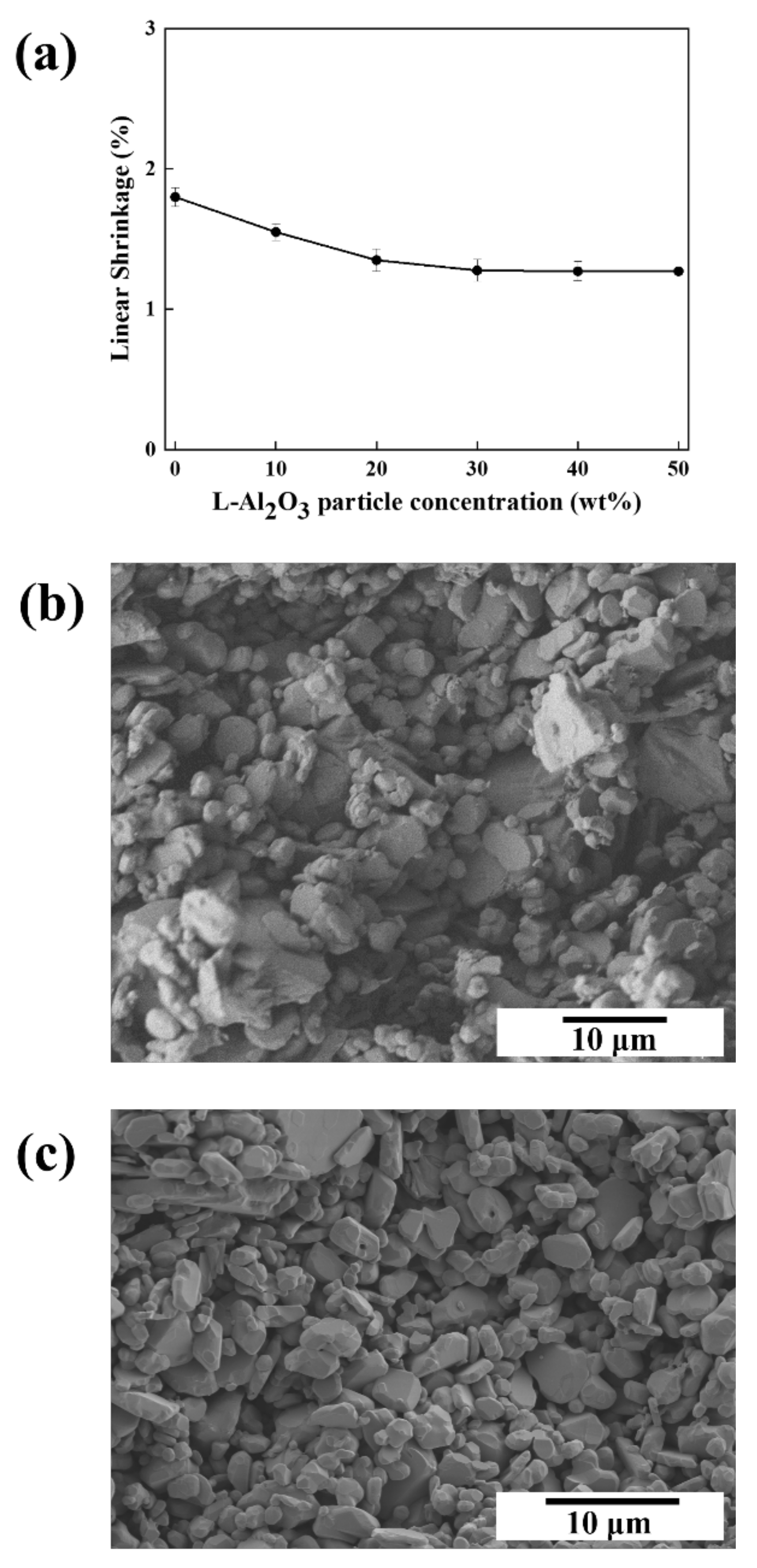
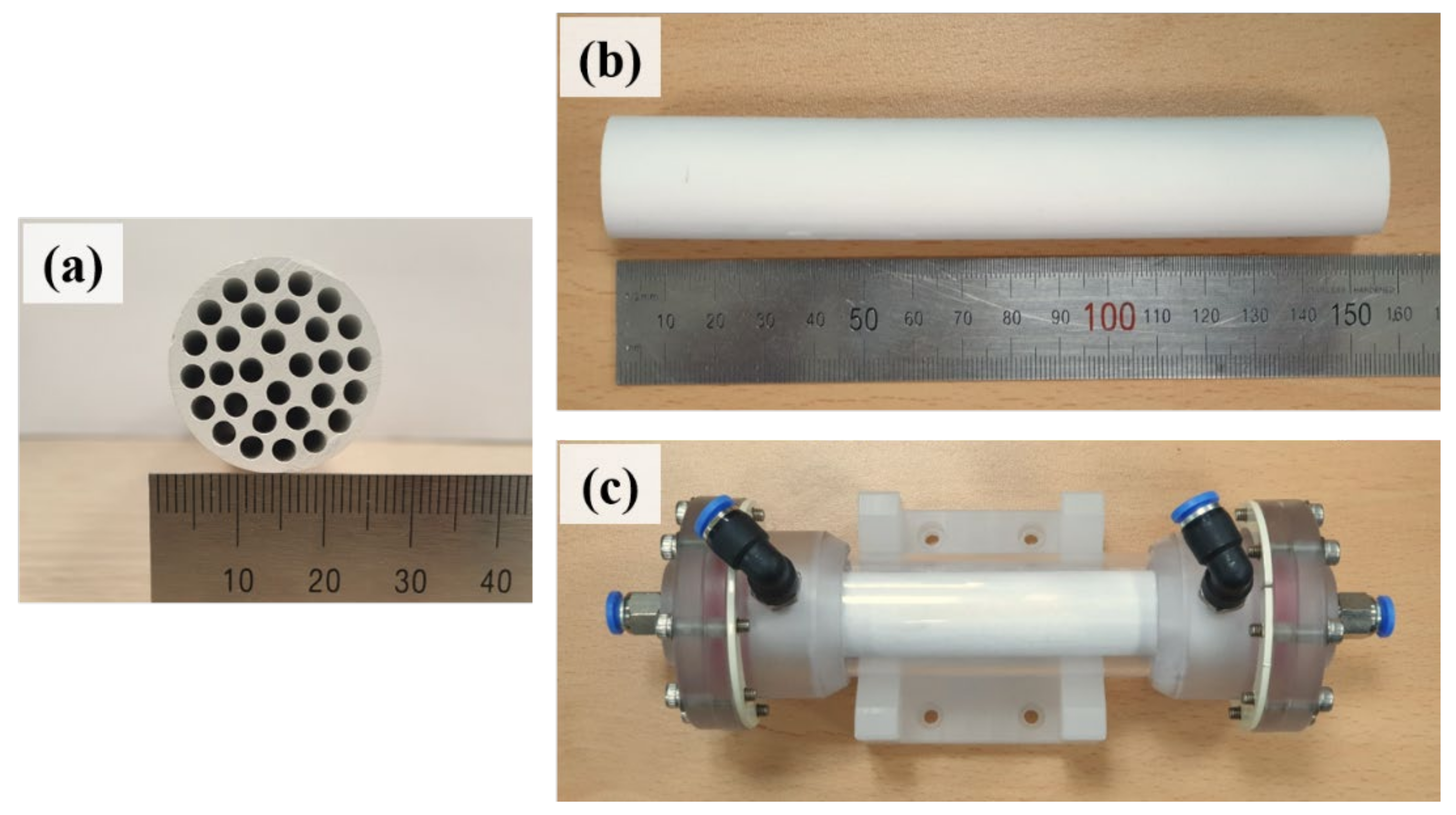
3.1. Multichannel Tubular Support

In an asymmetric filter configuration, support is a major component that provides overall mechanical strength and stability. The major issue in commercial-grade supports is crack generation during fabrication owing to shrinkage in the final product. To design a support suitable for industrial use with a minimal shrinkage rate, specimens made from various powder mixtures of S-Al2O3 and L-Al2O3 were analysed. Figure 1a shows the effect of the mixing ratio of the starting powder on the linear shrinkage rate. The S-Al2O3 exhibited a high shrinkage rate of approximately 2% without any addition. However, when S-Al2O3 and L-Al2O3 were mixed, the shrinkage rate continuously declined with increasing concentration of L-Al2O3. It consequently stabilised at a ratio of 70:30 for the S-Al2O3 and L-Al2O3, respectively.
The high shrinkage rate of the S-Al2O3 specimen may be related to the mean particle size. Particles with smaller mean sizes exhibited high sinterability owing to the high surface energy, causing shrinkage in the final product [23]. In contrast, in the mixture of alumina powders, the L-Al2O3 provided skeletal structure to the support, while the S-Al2O3 filled the pores among large particles. This facilitated consistent geometrical dimensions without any shrinkage in the final product [24]. As per the investigation, the final support layer was extruded by S-Al2O3 and L-Al2O3 in the ratio of 70:30, respectively.
To the best of our knowledge, the obtained average linear shrinkage rate for the final support layer was significantly smaller than the previously reported values, as listed in Table 2. This may be attributed to the fabrication of the support layer with the mixture of small and large alumina particles rather than with single-sized small particles as in previous studies.
Figure 1b shows an SEM image of an alumina support layer that had been heat treated at 1500 °C. A microstructure with well-sintered pore channels and an α-alumina phase can be easily identified. The mercury porosimetry results exhibited a narrow pore-size distribution with an open porosity of 37% and average pore size of 0.8 μm. As a comparison, a SEM image of the alumina support layer composed of only S-Al2O3 particles is given in Figure 1c.

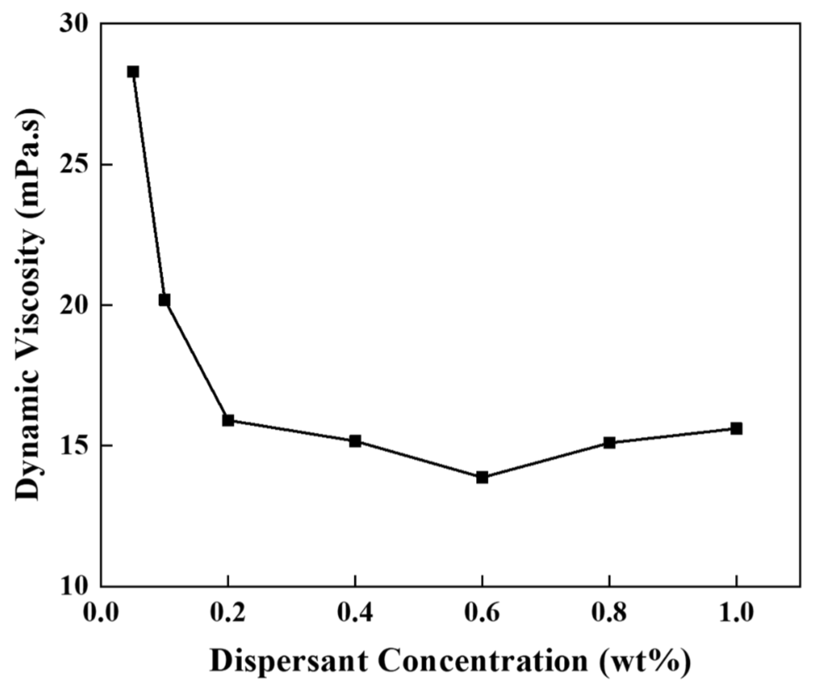
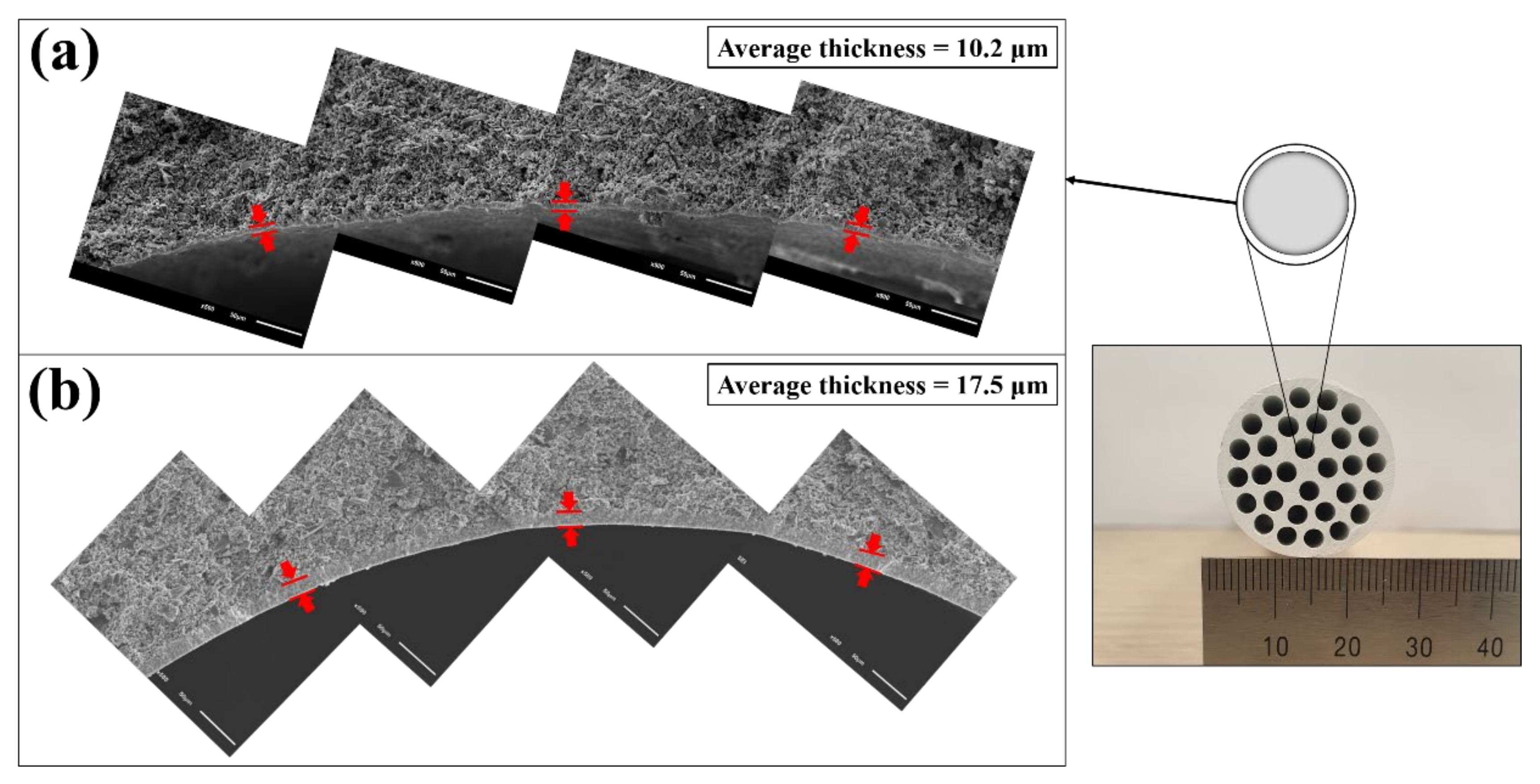
3.2. Alumina Microfiltration Membrane

An important advantage of using membrane filtration is the retention of the microorganisms present in the water, such as bacteria. The most harmful bacteria in water are usually larger than 0.4 μm [28]. To prevent the permeation of bacteria, the average pore size of the effective membrane layer must be smaller than the minimum size of the bacteria. Thus, it is necessary to apply a microfilter separation layer to a macroporous support prior to water filtration.
Conventional dip-coating was used to deposit the alumina microfiltration membrane on the multichannel support. The ceramic suspension for the dip-coating was prepared using the composition given in Table 1. Darvan-CN was added as a dispersing agent to enhance the dispersion of alumina particles in the suspension. The relationship between the dispersant and viscosity was studied to optimise its concentration. The amount of dispersant varied between 0.05 and 1 wt%, as shown in Figure 2. A ViscoQC™ 100-L viscometer (Anton Paar, Graz, Austria) was used to measure the viscosity at a shear rate of 30 s−1. The results indicated that the optimal amount of Darvan-CN was 0.6 wt% as this concentration offered the lowest viscosity (13.87 mPa·s).
The viscosity trend may be explained by the dissociation of Darvan-CN into negatively charged carboxylic groups that are absorbed on the positively charged alumina surface via attractive electrostatic forces. At the optimum concentration (0.6 wt%), the dispersant formed a monolayer on the alumina particles. As a result, the electrostatic repulsive forces generated and increased the fluidity of suspension [29,30]. At a lower concentration of dispersant, the particles were not completely covered with dissociative ions that led to partial attractive and repulsive forces, causing flocculation. Beyond the optimum concentration, the polymeric layers of the dispersant tended to agglomerate and make the suspension more viscous [31].
The coated support layers were subsequently dried at room temperature and then heat-treated at 1300 °C. This produced a membrane layer without any cracks. The average pore size of this microfiltration membrane was 0.09 μm, as determined by the mercury porosimetry.
We observed from the SEM analysis that the thickness of the bottom part of the membrane was larger than the thicknesses of the top and middle parts. This resulted in a nonuniform membrane along the support length. During the dip-coating, the bottom part of the support layer remained in contact with the suspension for a much longer time compared with the top and middle parts, forming a relatively thick layer. Based on this morphological analysis, membrane inhomogeneity may be controlled by fabricating a double-layered microfiltration membrane on the subsequent substrate. During the second dip-coating, the substrate was inverted so that the bottom side became the top, forming a uniform coating layer across the support.
Figure 3 shows a broad view of single- and double-coated microfiltration membranes. Figure 3a shows a non-uniform single-coated membrane with an average thickness of 10.2 μm. After the second coating, a homogeneous α-Al2O3 membrane, tightly integrated with the substrate, formed. It had a uniform coating with an average thickness of 17.5 μm, as displayed in Figure 3b.
In Figure 4, a cross-sectional SEM micrograph of a double-coated microfiltration membrane is presented. It is apparent from the SEM image that the double-coated microfiltration membrane was successfully developed on the multichannel tubular support without any defects.
The average pore size was 0.07 μm with a relatively narrow pore size distribution compared with that of the single-layered MF membrane, as shown in Figure 5.

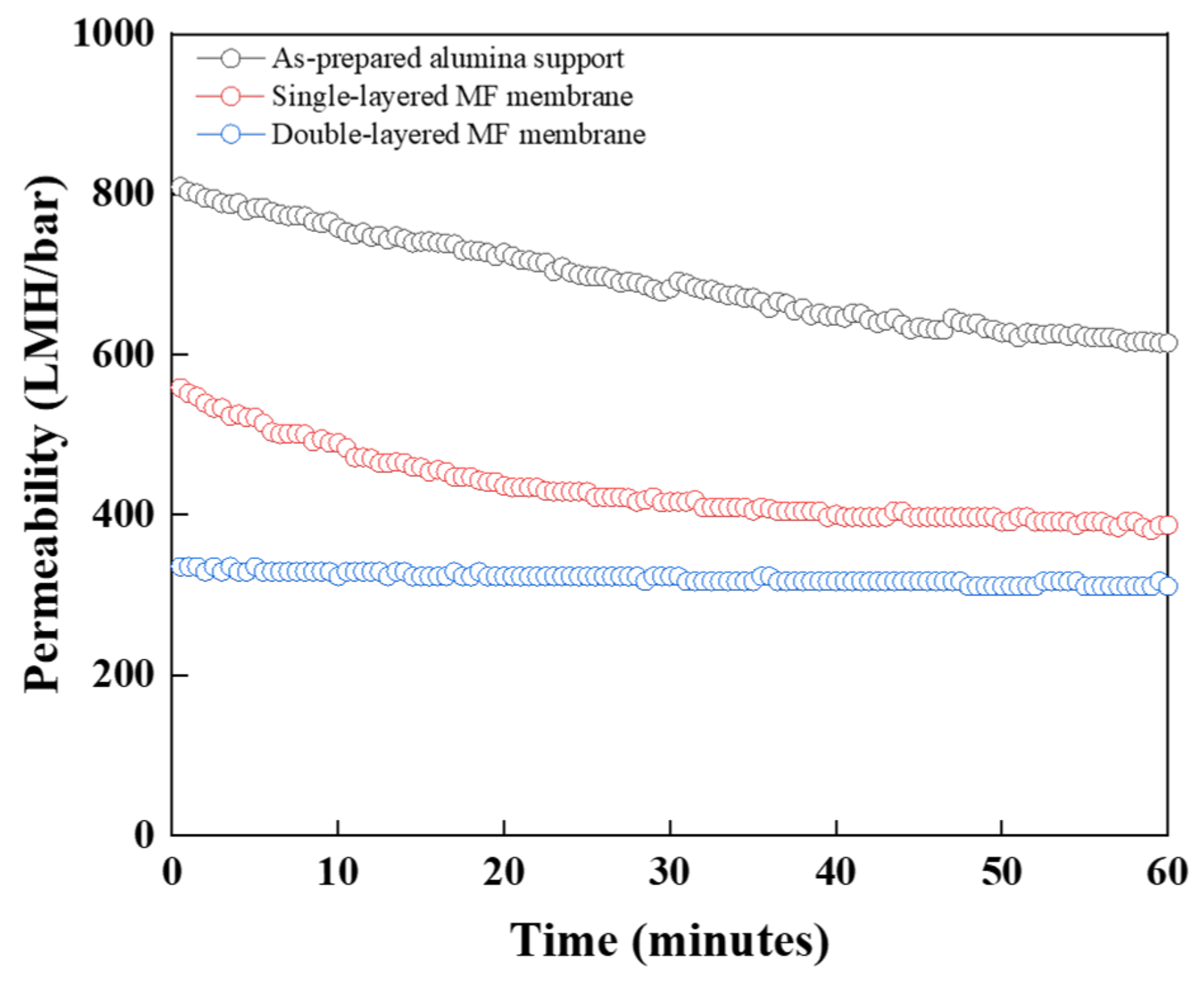
3.3. Pure Water Permeability

Figure 6 shows the membrane module of a dead-end microfiltration system installed in the laboratory used for the pure water permeability test.
Using this system, the pure water permeability was measured. As shown in Figure 7, the pure water permeability of the as-prepared support, single-layered MF membrane, and double-layered MF membrane were 614, 388, and 311 L m–2 h–1 bar–1, respectively. The main reasons for a slightly lower permeance of the double-layered MF membrane compared with the single-layered MF membrane were the increase in the thickness and decrease in the pore size. The pure water permeability curve of the double-layered MF membrane was more stable over time. This confirmed the presence of a crack-free membrane. If the top layer was defective, the permeability would not stabilise over time [32].
After the pure water permeability test, the cross-sectional areas of the multichannel cylindrical tubes were observed, as shown in Figure 8a,b. The deposition of contaminants was detected on the outer channels of the multichannel support layer and microfiltration membrane, while the inner channels were unaffected. This revealed that only the outer channels contributed to the water permeation flux, while the inner channels were not active. These unaffected channels were called dead zones [33].
This behaviour may be explained by the multichannel configuration of the support. The flow distance of the channels located far from the circumferential boundary, that is, the permeate side [9], was significantly larger than that of the channels near the boundary. Therefore, the pressure accumulated in the centre, and the feed tended to flow only from the outermost channels. Thus, the flow resistance of the inner channels became greater than that of the outer channels, which led to the generation of a dead zone in the inner channels. Figure 8 also shows that the microfiltration membrane layer had a smaller dead zone area than the as-prepared support. This was due to the small pore size of the microfiltration membrane, which allowed a uniform distribution of feed pressure across the channel rings. As a result, the area of the dead zone decreased, increasing the efficiency of the microfiltration membrane. Thus, a decrease in pore size decreased the formation of dead zones owing to the uniform distribution of feed pressure. This illustrated the high permeation stability of the double-layered microfiltration membrane compared with that of the support and single-layered microfiltration membrane.

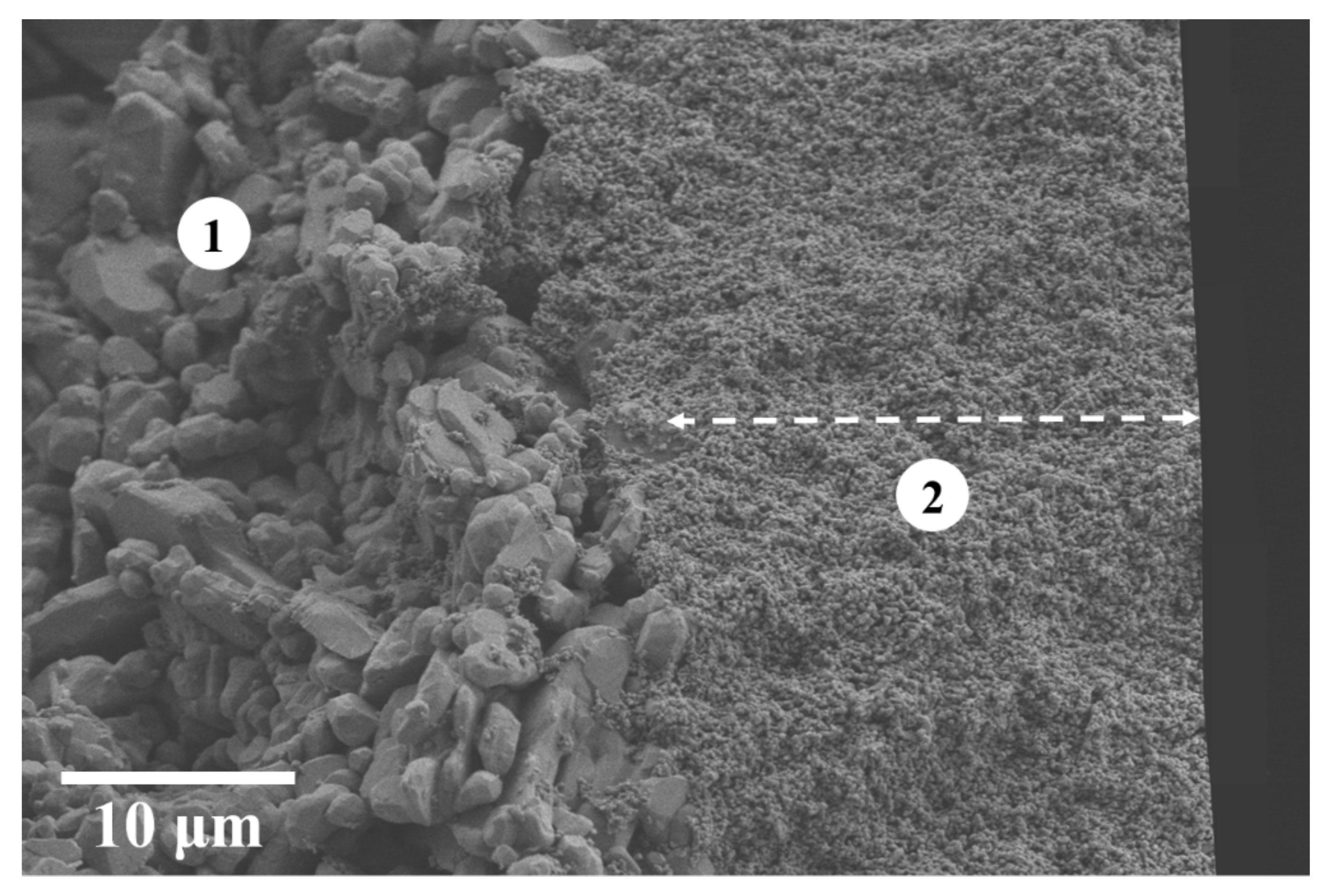
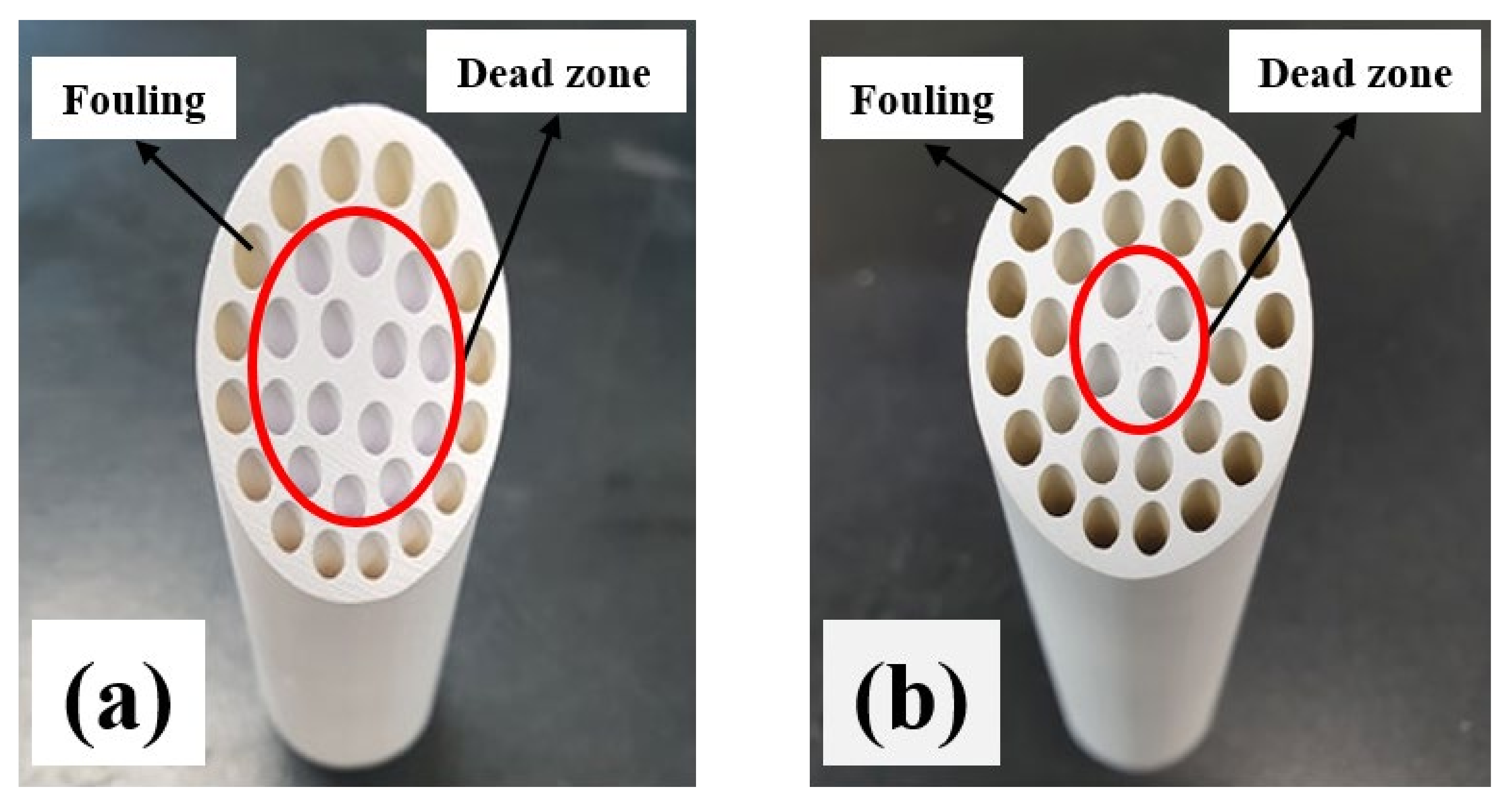
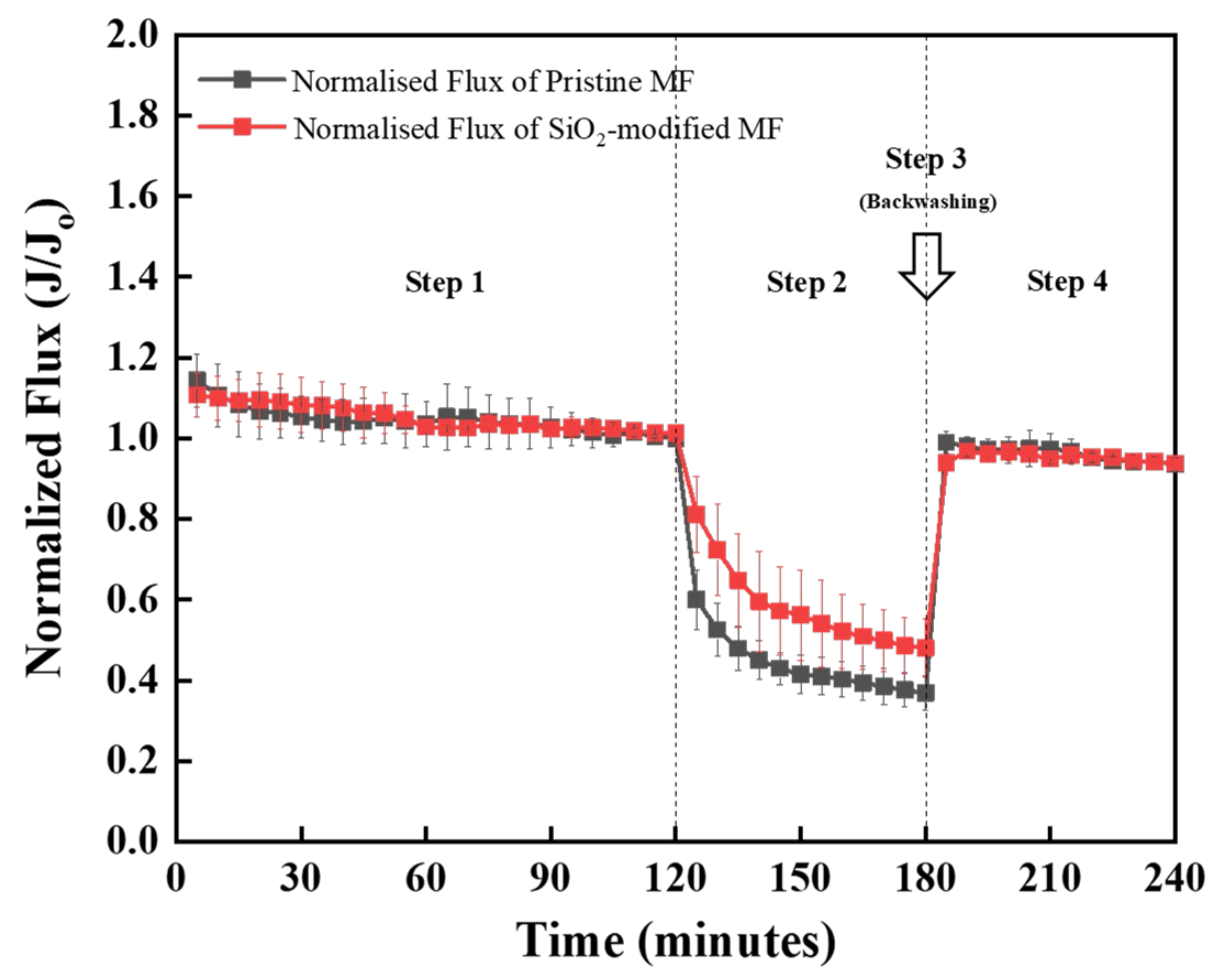
3.4. Surface Modification for Antifouling Properties

The objective of this study was to minimise the fouling of the microfiltration membrane, as shown in Figure 8. Fouling tends to reduce the permeate flux and thus increases the transmembrane pressure (TMP) and operational costs [34,35]. Surface modification is the most effective technique in this regard. Thus, experiments were conducted to investigate the influence of inorganic surface modification on the antifouling properties of multichannel microfiltration membranes.
The microfiltration membrane was surface-modified by a sol-gel technique using TEOS to form a SiO2 coating layer on the surface of the alumina particles.
The normalised time-dependent flux patterns of the pristine and silica-coated MF membranes at each step of the process are presented in Figure 9. In step 1, all microfiltration membranes maintained a stable flux. In step 2, during the supply of foulant (HA), the flux rapidly decreased for each microfiltration membrane, followed by a slower decline with time. The flux decline ratios were then estimated. After backwashing in step 3, the membranes were again permeated using DI water in step 4, and the flux recovery ratios were calculated. The flux decline ratio of the pristine membrane was 63%, which was higher than that of the surface-modified membrane (52%). However, the flux recovery ratio was 94% for the pristine and SiO2-modified membranes owing to the backwashing operation.
The isoelectric point (IEP) of α-alumina is 7.0–8.0, and that of HA is 4.7. In the neutral pH range (6.5–7.0) of water, strong attractive forces were generated between the alumina surface and HA, which significantly facilitated the membrane fouling. In contrast, the isoelectric point (IEP) of SiO2 is 1.0–2.0. Therefore, after the surface modification, the surface charge of the alumina membrane was altered, and strong repulsive forces were generated between the SiO2-modified membrane and HA, inhibiting the deposition of foulants. This proves the importance of surface modification.

4. Conclusions

In this study, we successfully extruded a multichannel cylindrical-tube-type support using alumina powder of various particle sizes with minimum linear shrinkage. An alumina coating was deposited twice to prepare a homogeneous microfiltration membrane. The mean pore size of the alumina support (0.8 μm) was reduced to 0.07 μm after the microfiltration membrane coating. The flux performance of the extruded support and microfiltration membranes was analysed. The multichannel extruded support showed a pure water permeability of 614 L·m−2·h−1·bar−1, while the double-layered microfiltration membrane exhibited a pure water permeability of 311 L·m−2·h−1·bar−1.
The effectiveness of the SiO2 modification on the pristine alumina membranes was demonstrated. The SiO2-coated membranes exhibited higher flux than the pristine MF membranes. The negatively charged SiO2-modified membrane inhibited the deposition of HA by strong electrostatic repulsive forces. Finally, our multichannel cylindrical tube type membrane support was effective for microfiltration.

Author Contributions

I.-H.S. conceived of and designed the experiments; D.N. performed the experiments, analysed the data, and wrote the paper; J.-H.H. and J.L. contributed to the formal analysis and writing—review and editing. All authors have read and agreed to the published version of the manuscript.

Funding

This research was funded by (1) the National R&D Program through the National Research Foundation of Korea (NRF) funded by Ministry of Science and ICT (grant number 2020M3H4A3106359) and (2) the Technology Innovation Program (20003782) of the Ministry of Trade, Industry and Energy.

Institutional Review Board Statement

Not applicable.

Informed Consent Statement

Not applicable.

Data Availability Statement

Not applicable.

Conflicts of Interest

The authors declare no conflict of interest.

References

  1. Fane, A.G.; Wang, R.; Jia, Y. Membrane Technology: Past, Present and Future. In Membrane and Desalination Technologies; Wang, L.K., Chen, J.P., Hung, Y.-T., Shammas, N.K., Eds.; Humana Press: Totowa, NJ, USA, 2011; pp. 1–45. [Google Scholar] [CrossRef]
  2. Studart, A.R.; Gonzenbach, U.T.; Tervoort, E.; Gauckler, L.J. Processing Routes to Macroporous Ceramics: A Review. J. Am. Ceram. Soc. 2006, 89, 1771–1789. [Google Scholar] [CrossRef]
  3. Cheong, H.; Cho, W.-S.; Ha, J.-S.; Kim, C.-S.; Choi, D.-K.; Cheong, D.-S. Structural evolution of alumina membrane prepared on an alumina support using a sol–gel method. J. Alloys Compd. 1999, 290, 304–309. [Google Scholar] [CrossRef]
  4. Gonzenbach, U.T.; Studart, A.R.; Steinlin, D.; Tervoort, E.; Gauckler, L.J. Processing of Particle-Stabilized Wet Foams Into Porous Ceramics. J. Am. Ceram. Soc. 2007, 90, 3407–3414. [Google Scholar] [CrossRef]
  5. Raether, F.; Iuga, M. Effect of particle shape and arrangement on thermoelastic properties of porous ceramics. J. Eur. Ceram. Soc. 2006, 26, 2653–2667. [Google Scholar] [CrossRef]
  6. Ha, J.-H.; Bukhari, S.Z.A.; Lee, J.; Song, I.-H. The preparation and characterizations of an alumina support layer as a free-standing membrane for microfiltration. Ceram. Int. 2015, 41, 13372–13380. [Google Scholar] [CrossRef]
  7. Nair, B.N. Synthesis, characterisation and gas permeation studies on microporous silica and alumina-silica membranes for separation of propane and propylene. J. Membr. Sci. 1996, 116, 161–169. [Google Scholar] [CrossRef] [Green Version]
  8. Rao, A.P.; Desai, N.V.; Rangarajan, R. Inorganic membranes: New materials for separation technology. J. Sci. Ind. Res. 1997, 56, 518–522. [Google Scholar]
  9. Yang, Z.; Cheng, J.; Yang, C.; Liang, B. CFD-based optimization and design of multi-channel inorganic membrane tubes. Chin. J. Chem. Eng. 2016, 24, 1375–1385. [Google Scholar] [CrossRef]
  10. Ha, J.-H.; Bukhari, S.Z.A.; Lee, J.; Song, I.-H.; Park, C. Preparation processes and characterizations of alumina-coated alumina support layers and alumina-coated natural material-based support layers for microfiltration. Ceram. Int. 2016, 42, 13796–13804. [Google Scholar] [CrossRef]
  11. Ha, J.-H.; Bukhari, S.Z.A.; Lee, J.; Song, I.-H. The membrane properties of alumina-coated alumina support layers and alumina-coated diatomite–kaolin composite support layers. Adv. Appl. Ceram. 2017, 117, 1–8. [Google Scholar] [CrossRef]
  12. Meng, S.; Zhang, M.; Yao, M.; Qiu, Z.; Hong, Y.; Lan, W.; Xia, H.; Jin, X. Membrane Fouling and Performance of Flat Ceramic Membranes in the Application of Drinking Water Purification. Water 2019, 11, 2606. [Google Scholar] [CrossRef] [Green Version]
  13. Dong, Y.; Lin, B.; Zhou, J.-E.; Zhang, X.; Ling, Y.; Liu, X.; Meng, G.; Hampshire, S. Corrosion resistance characterization of porous alumina membrane supports. Mater. Charact. 2011, 62, 409–418. [Google Scholar] [CrossRef]
  14. Dilaver, M.; Hocaoglu, S.M.; Soydemir, G.; Dursun, M.; Keskinler, B.; Koyuncu, I.; Ağtaş, M. Hot wastewater recovery by using ceramic membrane ultrafiltration and its reusability in textile industry. J. Clean. Prod. 2018, 171, 220–233. [Google Scholar] [CrossRef]
  15. Damas, S.B.; Alcaina-Miranda, M.I.; Bes-Piá, A.; Iborra-Clar, M.I.; Iborra-Clar, A.; Mendoza-Roca, J.-A. Ceramic membrane behavior in textile wastewater ultrafiltration. Desalination 2010, 250, 623–628. [Google Scholar] [CrossRef]
  16. Nandi, B.; Das, B.; Uppaluri, R.; Purkait, M. Microfiltration of mosambi juice using low cost ceramic membrane. J. Food Eng. 2009, 95, 597–605. [Google Scholar] [CrossRef]
  17. Chang, Y.; Ling, Z.; Liu, Y.; Hu, X.; Li, Y. A simple method for fabrication of highly ordered porous α-alumina ceramic membranes. J. Mater. Chem. 2012, 22, 7445–7448. [Google Scholar] [CrossRef]
  18. Ebrahimi, M.; Kerker, S.; Schmitz, O.; Schmidt, A.A.; Czermak, P. Evaluation of the fouling potential of ceramic membrane configurations designed for the treatment of oilfield produced water. Sep. Sci. Technol. 2017, 53, 349–363. [Google Scholar] [CrossRef]
  19. Ha, J.-H.; Lee, S.; Bukhari, S.Z.A.; Lee, J.; Song, I.-H.; Lee, S.J.; Choi, J. Effects of preparation conditions on the membrane properties of alumina-coated silicon carbide supports. J. Ceram. Soc. Jpn. 2018, 126, 860–869. [Google Scholar] [CrossRef]
  20. Wang, F.; Lee, J.; Ha, J.-H.; Song, I.-H. Surface modification of alumina membranes via a sol-gel process for antifouling properties. Mater. Lett. 2017, 191, 200–202. [Google Scholar] [CrossRef]
  21. Lee, J.; Ha, J.-H.; Song, I.-H.; Park, J.-W. Effect of SiO2 coating on alumina microfiltration membranes on flux performance in membrane fouling process. J. Ceram. Soc. Jpn. 2019, 127, 35–43. [Google Scholar] [CrossRef]
  22. Esfahani, M.R.; Stretz, H.A.; Wells, M.J. Comparing humic acid and protein fouling on polysulfone ultrafiltration membranes: Adsorption and reversibility. J. Water Process Eng. 2015, 6, 83–92. [Google Scholar] [CrossRef]
  23. Yeh, T.-S.; Sacks, M.D. Effect of Particle Size Distribution on the Sintering of Alumina. J. Am. Ceram. Soc. 1988, 71, C-484–C-487. [Google Scholar] [CrossRef]
  24. Ma, J.; Lim, L. Effect of particle size distribution on sintering of agglomerate-free submicron alumina powder compacts. J. Eur. Ceram. Soc. 2002, 22, 2197–2208. [Google Scholar] [CrossRef]
  25. Shqau, K.; Mottern, M.L.; Yu, D.; Verweij, H. Preparation of defect-free porous alumina membrane supports by colloidal filtration. In Proceedings of the 6th Pacific Rim Conference on Multimedia, Jeju Island, Korea, 11–13 November 2005; pp. 20–21. [Google Scholar]
  26. Shqau, K.; Mottern, M.L.; Yu, D.; Verweij, H. Preparation and Properties of Porous alpha-Al2O3 Membrane Supports. J. Am. Ceram. Soc. 2006, 89, 1790–1794. [Google Scholar] [CrossRef]
  27. Qi, H.; Niu, S.; Jiang, X.; Xu, N. Enhanced performance of a macroporous ceramic support for nanofiltration by using α-Al2O3 with narrow size distribution. Ceram. Int. 2013, 39, 2463–2471. [Google Scholar] [CrossRef]
  28. Cooper, A.; Floreani, R.; Ma, H.; Bryers, J.D.; Zhang, M. Chitosan-based nanofibrous membranes for antibacterial filter applications. Carbohydr. Polym. 2012, 92, 254–259. [Google Scholar] [CrossRef] [PubMed] [Green Version]
  29. Bukhari, S.Z.A.; Ha, J.-H.; Lee, J.; Song, I.-H. Viscosity Study to Optimize a Slurry of Alumina Mixed with Hollow Microspheres. J. Korean Ceram. Soc. 2015, 52, 403–409. [Google Scholar] [CrossRef] [Green Version]
  30. Greenwood, R.; Bergström, L. Electroacoustic and rheological properties of aqueous Ce-ZrO2 (Ce-TZP) suspensions. J. Eur. Ceram. Soc. 1997, 17, 537–548. [Google Scholar] [CrossRef]
  31. Briscoe, B.J.; Khan, A.U.; Luckham, P. Optimising the dispersion on an alumina suspension using commercial polyvalent electrolyte dispersants. J. Eur. Ceram. Soc. 1998, 18, 2141–2147. [Google Scholar] [CrossRef]
  32. Wang, L.; Song, L. Flux decline in crossflow microfiltration and ultrafiltration: Experimental verification of fouling dynamics. J. Membr. Sci. 1999, 160, 41–50. [Google Scholar] [CrossRef]
  33. Doleěk, P. Mathematical modelling of permeate flow in multichannel ceramic membrane. J. Membr. Sci. 1995, 100, 111–119. [Google Scholar] [CrossRef]
  34. Shannon, M.A.; Bohn, P.W.; Elimelech, M.; Georgiadis, J.G.; Mariñas, B.J.; Mayes, A.M. Science and technology for water purification in the coming decades. Nature 2008, 452, 301–310. [Google Scholar] [CrossRef]
  35. Madaeni, S.S.; Mohamamdi, T.; Moghadam, M.K. Chemical cleaning of reverse osmosis membranes. Desalination 2001, 134, 77–82. [Google Scholar] [CrossRef]
Figure 1. (a) Effect of large alumina particle (L-Al2O3) concentration on the linear shrinkage of extruded support layer. (b) Typical SEM image of extruded alumina support layer composed of a mixture of S-Al2O3 and L-Al2O3 particles (70:30). (c) Typical SEM image of extruded alumina support layer composed of S-Al2O3 particles.
Applsci 12 07993 g001
Figure 2. Effect of increasing dispersant concentration on the viscosity of Al2O3 suspension for microfiltration coating.
Applsci 12 07993 g002
Figure 3. (a) SEM image of single-coated alumina microfiltration membrane. (b) SEM image of double-coated alumina microfiltration membrane (red-arrows represent the thickness of the MF membrane layer).
Applsci 12 07993 g003
Figure 4. Cross-sectional SEM image of the asymmetric multichannel cylindrical tube-type substrate; (1) alumina macroporous support; (2) double-coated alumina microfiltration layer.
Applsci 12 07993 g004
Figure 5. Pore size distribution of extruded support layer and alumina microfiltration (MF) membrane.
Applsci 12 07993 g005
Figure 6. (a,b) Images of multichannel cylindrical-tube-type microfiltration filter. (c) Image of microfiltration filter mounting module for water permeability test.
Applsci 12 07993 g006
Figure 7. Pure water permeability of extruded support layer and alumina microfiltration (MF) membranes.
Applsci 12 07993 g007
Figure 8. Cross-section of a multichannel cylindrical tube after pure water permeability test. (a) As-prepared support and (b) microfiltration membrane layer.
Applsci 12 07993 g008
Figure 9. Normalised flux behaviour of pristine microfiltration (MF) membrane and surface-modified microfiltration (MF) membrane with humic acid (HA) solution (10 mg/L, pH 6.5).
Applsci 12 07993 g009
Table 1. Slurry composition for dip-coating of alumina on multichannel cylindrical-tube-type support layer.
Slurry Composition
PowderSolventsBinder
AKP-30H2OIPAPVA
8 wt%57 wt%33 wt%2 wt%
Darvan-CN added as a dispersant.
Table 2. Linear shrinkage rate of reported alumina support layer.
Alumina PowderParticle Size
(μm)
Temperature
(°C)
Linear Shrinkage
(%)
Reference
A3000.3140014[25]
A6000.6130010[26]
A11001.1140012[27]
AM2104.815001.67Our work
S/L Al2O34.8/15.6615001.27Our work
Publisher’s Note: MDPI stays neutral with regard to jurisdictional claims in published maps and institutional affiliations.

