Article

Investigation of the Effect of Child Helmet Design Parameters on Head and Brain Injuries Using Reduced-Order Modelling

by
Nattawood Prasartthong
1 and
Julaluk Carmai
1,2,*
1
The Sirindhorn International Thai-German Graduate School of Engineering (TGGS), King Mongkut’s University of Technology North Bangkok, Bangkok 10800, Thailand
2
Automotive Safety and Assessment Engineering Research Centre, King Mongkut’s University of Technology North Bangkok, Bangkok 10800, Thailand
*
Author to whom correspondence should be addressed.
Appl. Sci. 2022, 12(16), 8016; https://doi.org/10.3390/app12168016
Submission received: 8 July 2022 / Revised: 8 August 2022 / Accepted: 8 August 2022 / Published: 10 August 2022
(This article belongs to the Section Mechanical Engineering)

Abstract

:
A helmet is the main protective equipment for a child pillion passenger. A safe helmet must be able to mitigate head and brain injuries resulting from high head impact loading. A lightweight helmet is preferable, especially for children. This paper proposed to study the effect of materials, liner thickness, and friction at the head–helmet interface on linear and rotational accelerations using reduced-order modelling. A child head–helmet finite element model was developed and validated against an experiment. Finite element simulations were conducted to generate training data for the establishment of reduced-order models which were subsequently used to predict the linear and rotational accelerations for various helmet parameters. The prediction could be performed in a very short time compared to its corresponding finite element simulation. The use of aluminium foam enhanced mitigation of the linear and rotational accelerations as well as weight reduction. This study also revealed that the head–helmet friction coefficient had a strong effect on the rotational acceleration, while the liner thickness predominantly affected the linear acceleration. However, the liner thickness had less influence on the rotational acceleration when the head–helmet friction was low. The risk of brain concussion as well as diffusional injury could be reduced by enabling low friction at head–helmet surface.

1. Introduction

Road traffic fatalities involving motorcycles are the most common in Thailand. They accounted for 74% of traffic deaths as reported by the World Health Organization in 2018 [1]. Motorcycle accident analysis in Thailand has gained more interest from many researchers over the past 4 years [2,3,4,5,6,7,8,9,10] in order to suggest the development of countermeasures for reducing motorcycle crashes and fatalities [11,12]. Champahom et al. [10] recently investigated factors affecting the severity of motorcycle accidents. They concluded that age, road lanes, and helmet wearing were significant factors that influenced the severity of motorcycle accidents on Thailand’s arterial roads. Wearing a helmet could likely lead to less severity during crashes [13]. Jomnonkwao et al. [8,9] studied helmet-wearing intention and behavior among students in an urban and rural areas and suggested that activities for promoting helmet intention should emphasize that parents could increase the helmet use intention of their children. Save the Children Thailand reported that there were 1.3 million child pillion passengers on motorcycles in 2018 [14]. Child pillion passengers were among the road accident victims. Koetniyom et al. [2] performed motorcycle crash tests with a child pillion passenger behind and before the rider to study the kinematics of the rider and passenger. Their results revealed that the child sitting at the back of the rider had a higher risk of severe head injury, while the child sitting in front of the rider had a higher risk of thorax and neck injury. They recommended the child sitting behind the rider with a safety helmet and a child seat would be safer [2]. The most effective strategy for child head protection during impact is a helmet. However, inappropriate head protection equipment for small child pillions may cause disability or slow brain development process among child pillions. Nevertheless, most helmets sold for children are reduced-size adult helmets which have not taken into account the different anthropometry. In addition, the injury mechanism of children and adults has some differences [15]. The cervical spine of children is weaker than that of adults. A lightweight helmet is preferable for a child to reduce the load on the neck. The helmet should also have high energy absorption with a mechanism that can mitigate head acceleration. Apart from the head linear acceleration, the head rotational acceleration is also a critical response that can lead to mild traumatic brain injury [16]. Carmai et al. [3] analyzed overall kinematics and injury mechanisms of a rider and a child pillion passenger in various accident configurations. They reported a high risk of diffuse axonal injury (DAI) for the child pillion passenger during the car impacting motorcycle. The rotational acceleration on the brain causes a shear effect which induces diffuse axonal injury [17]. An oblique impact which is the most common type of head impact occurred during real-world motorcycle accidents [16]. The normal and tangential force induced in an oblique impact can lead to translational and rotational head motion [18,19,20,21]. The latter is thought to be the main cause of traumatic brain injury [18,19,20,21].
A good performance child helmet must be able to mitigate linear and rotational accelerations as well as be lightweight. A helmet normally consists of two main parts, an outer shell and an inner liner. Acrylonitrile butadiene styrene (ABS) is basically used as an outer shell material to resist penetration and to distribute the impact load on a wider area, while the inner liner is usually made of expandable polystyrene (EPS) foam to absorb most of the impact energy, hence lowering the linear acceleration. A weight reduction in the helmet can be achieved by decreasing liner thickness or introducing an innovative material such as aluminium foam (Al-foam) which has a high strength-to-weight ratio and good energy absorbing capability [22,23].
In the oblique impact conditions, velocities are connected with rolling and sliding phenomena. Friction, therefore, plays important role in reducing the rotational acceleration. The friction coefficient between the outer shell and ground has been recently investigated and reported that the friction between the helmet and the ground was among the factors that control the head rotational acceleration in oblique impacts [24,25,26,27]. Meng et al. [27] also revealed that a lower friction coefficient between the helmet outer shell and ground led to a higher reduction in brain tissue strain in the sliding regime. However, with similar underlying mechanics, the tangential component of the contact force can also cause rolling/sliding motion between the head and the helmet liner interface too [28]. Juste-Lorente et al. [29] investigated the effect of friction at the interface between the interior of the helmet and the headform on head impact biomechanics using the bare and the covered headform. They reported that the effects of the headform surface depended on the magnitude of the tangential velocity [29]. The coefficient of friction between the helmet’s interior and the head, therefore, plays an important role in the head rotational acceleration.
This paper aims to study the effect of advanced materials, liner thickness and the friction coefficient between head–helmet interaction on linear and rotational accelerations using a combined finite element and model reduction technique. Parametric studies or optimization problems require a number of cases, hence the high computational costs. The combined approach resulting in a so-called reduced-order model was introduced to address the time-consuming issue of the finite element simulations. The reduced-order model was used to generate a large number of data so that the effect of liner thickness and the head–helmet friction coefficient on head accelerations can be investigated continuously.

2. Materials and Methods

Numerical modelling together with the model reduction techniques were employed in this study. Finite element model of the helmet impact test was developed and validated with the experimental tests. Effects of material used for the outer shell and the inner liner was investigated first. Then, the commercial child helmet was slightly modified and used to generate a set of training data to establish a reduced-order model based on the proper orthogonal decomposition and the Kriging methods. The training data were generated from finite element simulations with various inner liner thickness and the head–helmet interface friction coefficients. This reduced-order model was subsequently used to generate a large set of data with a range of liner thickness and head–helmet friction coefficients as input parameters. The head injury responses measured in this study were the peak linear acceleration and the rotational acceleration. The linear acceleration relates to the skull fracture and brain contusion. However, the brain can be injured due to concussion and diffuse axonal injury (DAI) without a skull fracture. The rotational acceleration and the brain principal strain relate to brain injury [19,20,21]. In fact, the rotational kinematic outputs are correlated to brain strains [30,31,32,33]. Kelkar et al. [31] reported that the cumulative strain damage measure (CSDM) and the maximum principal strain (MPS) were the two brain strain measures which were proportional to peak rotational accelerations [31]. The CSDM is based on the brain’s cumulative volume fraction calculation, which has experienced a specific level of stretch (the maximum principal strain). They can also be used for predicting risk of brain injuries [31,32,33].

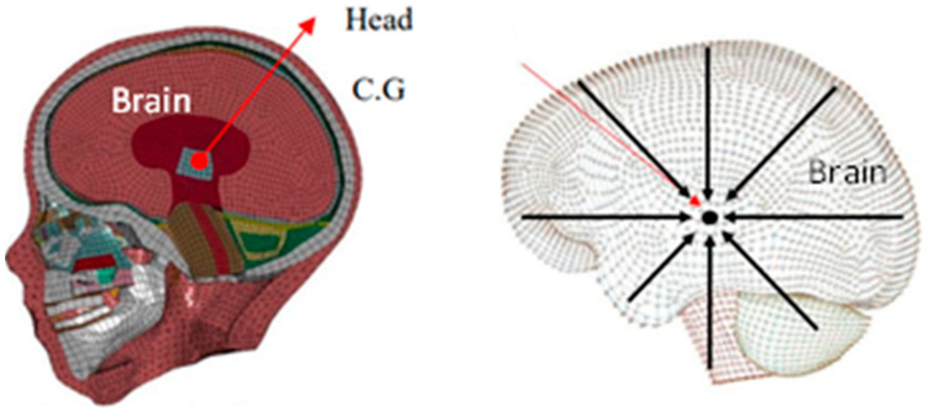
2.1. Finite Element Model Preparation and Validation

A commercial motorcycle helmet available for pre-school children in Thailand was selected as a reference in this study. It was a typical half helmet type with a 52-inch circumferential, as shown in Figure 1. The shell and foam liner of the helmet were scanned in 3 dimensions in order to obtain the correct profile of the helmet and liner. The liner was cut in half to measure the thickness, as shown in Figure 1b. The liner thickness was not uniform. The total weight of the outer shell and inner liner was 0.355 kg. The CAD model was created based on the 3D scan surface. The outer shell as well as the liner thickness were measured.
The outer shell was modelled using shell elements of 3.3 mm thickness, while solid elements were used for the inner liner. The inner liner had non-uniform thickness that varied from 12 mm at the front to 20 mm in the vertex, as shown in Figure 1b. The outer shell was made of acrylonitrile butadiene styrene (ABS). Its behavior was described using the plastic kinematics material model [34] in LS-DYNA with a mass density of 1200 kg/m3, a Young’s modulus of 4000 MPa, and a Poisson’s ratio of 0.37 [35]. The inner liner was made of expanded polystyrene (EPS). Its compression behavior was described using the low-density foam material model in LS-DYNA [34] with a mass density of 90 kg/m3, a Young’s modulus of 8.64 MPa, and a Poisson’s ratio of 0 [35,36]. The head of a 6-year-old child human body model (6YO THUMS) was employed as a tool to measure the injury during the impact. The head was developed by Toyota Motor Cooperation and validated in terms of compression and drop tests as reported in [37]. The peak linear acceleration was measured at the centre of gravity (C.G.) of the head, while the rotational acceleration was obtained by calculating the interpolation of the values from all nodes of the brain parts, as shown in Figure 2.
The 6YO THUMS head was assembled to the helmet. The head–helmet model was set to simulate the impact tests. Two protocols of impact tests, the department of transportation (DOT) FMVSS 218 helmet safety standard [38] and the modified helmet drop test to reflect an oblique impact proposed by Bourdet et al. [16], were considered. The standard helmet drop test based on the DOT FMVSS 218 required an anvil to place horizontally, while the modified drop test required a flat anvil to make an angle of 45° with the horizontal plane. This head–helmet finite element model was validated against the DOT drop tests conducted by Prasartthong et al. [39].

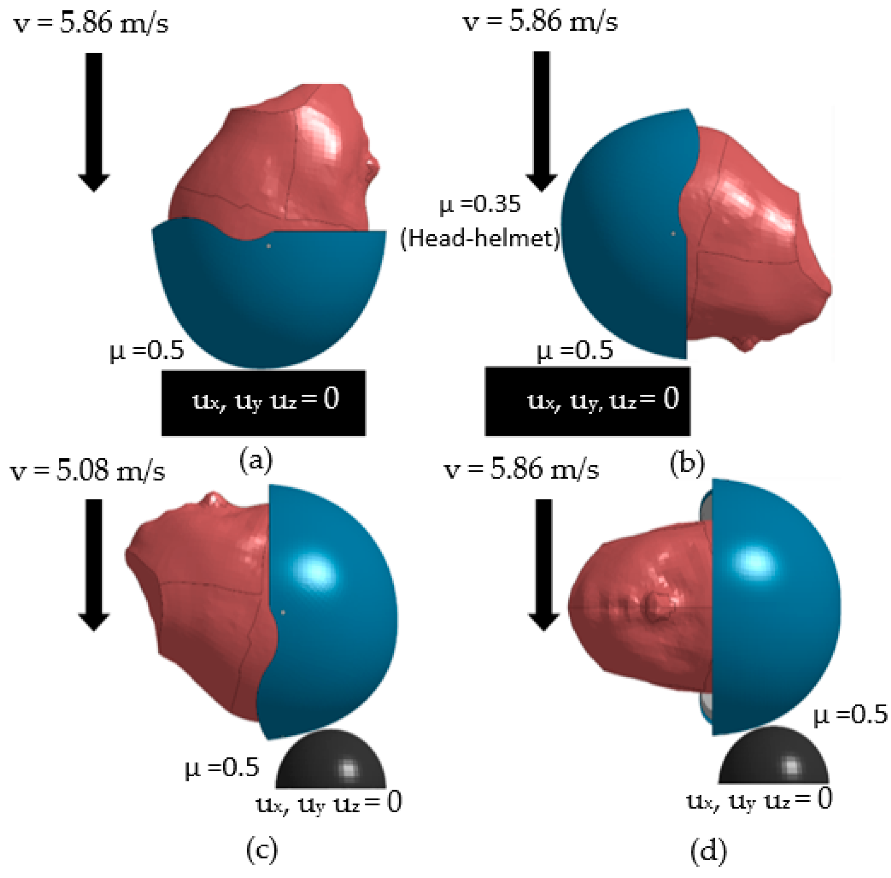
2.1.1. Impact Configurations According to the DOT FMVSS 218

The DOT drop test requires four locations of the helmet to be assessed. They were crown, front, rear, and side locations. A flat anvil was used for the crown and the front locations, while a hemisphere anvil was used for the rear and side locations. The head–helmet model was set to impact the rigid flat and hemisphere anvils at 5.86 and 5.08 m/s, respectively, to simulate the experiments of Prasartthong et al. [39]. The anvil was restricted to move in all directions. The coefficient of friction between helmet and head as well as helmet and anvil were 0.35 and 0.50 [40], respectively. The model setup for each impact location is shown in Figure 3. The linear acceleration was measured at the C.G. of the head. The DOT drop test adopted the maximum force as a guide to set the maximum allowable peak linear acceleration at 400 g.

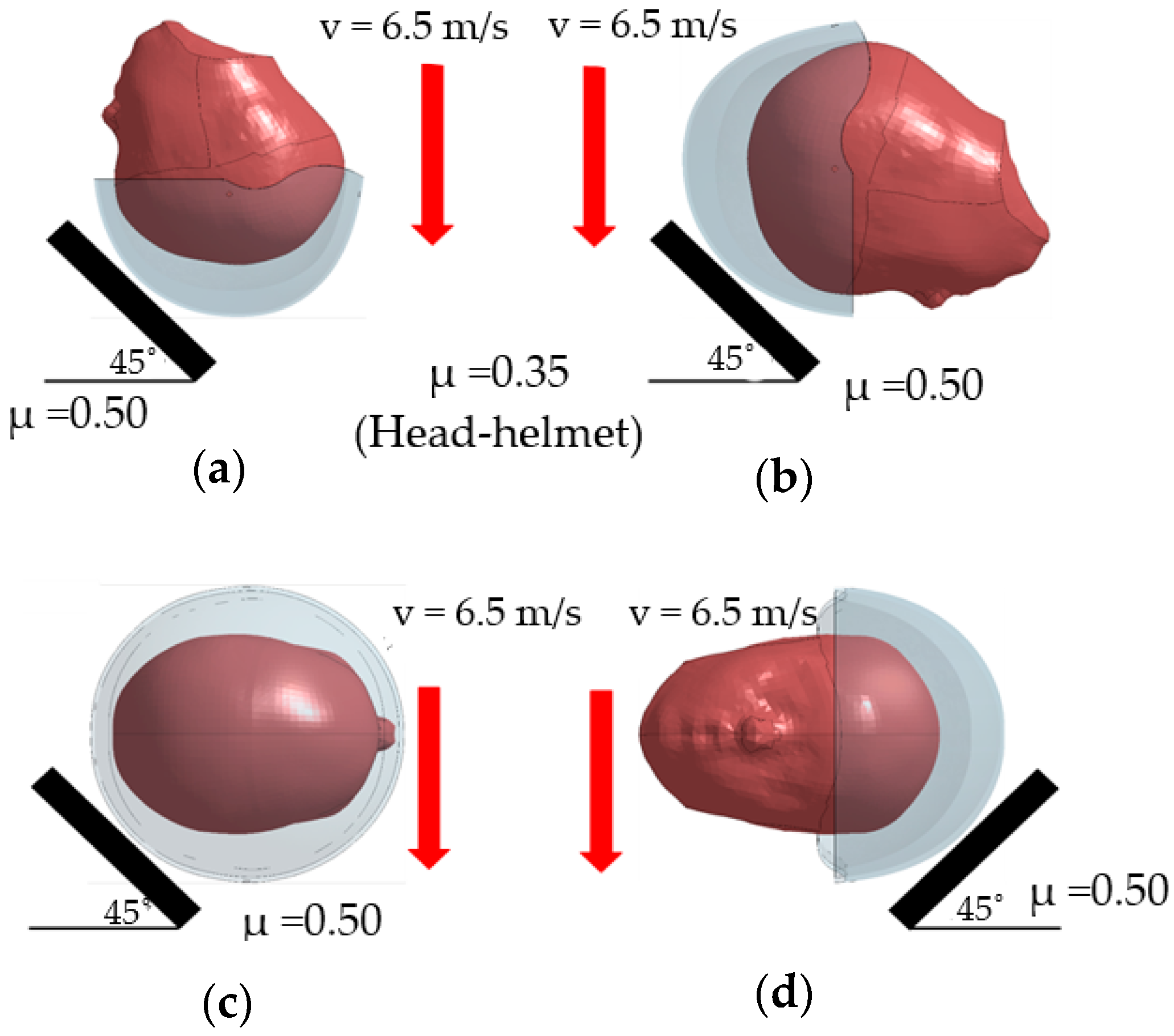
2.1.2. Impact Configurations According to the 45° Inclined Anvil Drop Tests

In real-world accidents, oblique impacts are the most common type of head impacts occurred during motorcycle collisions. Kleiven [40] discovered that the oblique impact induced the head rotational acceleration. The rotational kinematics have more influence on the brain injury than the translational kinematics [40]. However, there is no motorcycle helmet test standard that considers and assesses according to the head rotational acceleration [41]. In order to study the helmet protection performance of brain injury, additional tests proposed by Bourdet et al. [16] were also employed. This new drop test configuration was developed based on the real-world accidents. The helmeted head was dropped against a 45° inclined flat anvil. Four impact locations, crown, front, rear and side, were proposed. The finite element model for the 45° inclined flat anvil drop test is shown in Figure 4. The flat anvil made a 45° angle with the horizontal plane and was constrained to move in all directions. The coefficient of friction between helmet and head was 0.35. While the coefficient of friction between helmet and anvil was 0.50. The head–helmet model was dropped at a speed of 6.5 m/s.

2.2. Simulation Cases According to Various Helmet Design Parameters

A good head protection performance helmet must be able to mitigate skull and brain injury as well as resist penetration. The lightweight helmet is also preferable for a child to reduce the load on the neck. Materials used for producing helmets must have the ability to absorb energy during impact [36,42]. Al-foam is among the potential materials that have a great ability in impact energy absorption. Al-foam also possesses low density with good shear and fracture strength. This paper considers two materials, ABS and Al-foam, for the outer shell as well as EPS with two densities and Al-foam for the inner liner. The thickness of the inner liner and friction between the head and helmet were also investigated.

2.2.1. Simulation Cases for Studying the Effect of Materials

Two material types, ABS and Al-foam, with 140 kg/m3 density were used for the outer shell of the baseline helmet model, while EPS of 90 and 50 kg/m3 densities and Al-foam were considered for the inner liner. The model setup is shown in Table 1. Each model was used to simulate the DOT and inclined drop tests at 4 impact locations as illustrated in Figure 3 and Figure 4. Forty finite element simulations were conducted.

2.2.2. Simulation Cases for Studying the Effect of Inner Liner Thickness and Head–Helmet Friction

To study the effect of liner thickness, the liner was modified to have a uniform thickness. As a result of material effect, the helmet model for further studies employed 4 mm Al-foam as the outer shell. However, a 0.5 mm thin layer of ABS was also included as the first outer layer of the helmet shell. This was to enhance the penetration resistance of sharp objects. The inner liner material was EPS 50 kg/m3. In addition, the original half helmet shape was modified by extending the rear part to 72 mm to cover 3/4 of the skull. It is more like an open-face helmet which provides better head injury protection than the half-helmet type as reported by Hsu et al. [43]. The modified helmet model is shown in Figure 5. The inner liner thickness was 10, 15 and 20 mm. The friction coefficient between helmet and head was 0.05, 0.35 and 0.65.
Nine helmet models were setup according to variation of the thickness and friction coefficient as illustrated in Table 2. They were used in simulations of the DOT and the inclined anvil drop tests. Nine simulations were required for each impact location for each category of drop test. A total of 72 simulations were conducted. To investigate the optimal rage of the inner liner thickness and the head–helmet friction, a number of simulations were required so that the effect of the parameters on the output responses can be investigated more continuously. The reduced-order model (ROM) was introduced with the use of these finite element simulation results as the training data. The establishment of the ROM is described in the next section.
Apart from the training data, the validation data were also required for comparisons with the ROM predictions. The simulation cases were given in Table 3. A total of 24 simulations were required to assess the prediction performance of the ROM.

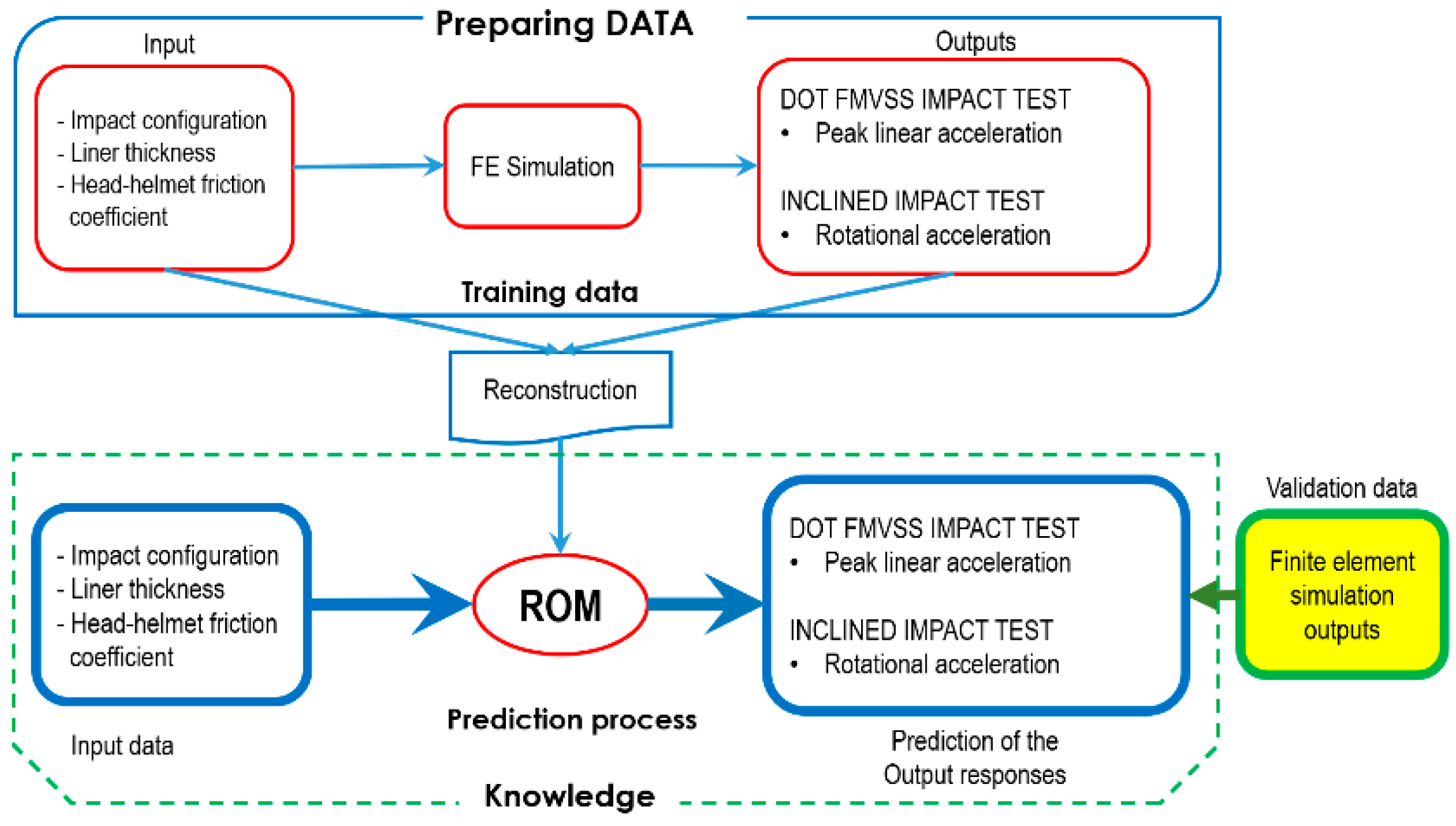
2.3. Reduced-Order Model Establishment

The finite element simulations for various thicknesses and friction coefficients were limited due to calculation times. A short calculation time with acceptable prediction accuracy would benefit the parametric studies. A predictive model which provides output response in a much shorter time is preferable. In this study, a predictive model was established based on a model reduction technique proposed by Kayvantash [44]. The reduced-order modelling consists of a learning step and a predictive step as in the case of a supervised learning algorithm. For the learning step, the proper orthogonal decomposition (POD) algorithm was employed to decompose the original dataset from the physical reference frame onto a new set of basis with special and useful properties. The result of decomposition and projection was a decouple version of the original dataset in another vector basis. Predictions of new space-time responses were reconstructed via multiplication of two interpolated uncouple fields. The Kriging method was selected for the spatial interpolation. The algorithm was implemented using the ODYSSEE software [45] for ROM modelling. Figure 6 shows the process of ROM establishment. The upper block was the process of obtaining the training data which were provided by the finite element simulations. Thirty-six training data were the finite element simulation results with 3 thickness and 3 friction coefficients with 4 impact configurations for each type of drop test. Two ROMs were established. One for the DOT drop test to predict the head linear acceleration. The other was for the 45° inclined drop test to predict the rotational acceleration. The inputs were the impact configuration, the liner thickness and the head–helmet friction coefficient. Comparisons of the prediction with the finite element calculation were performed to validate the ROM. Finite element simulation results with the conditions illustrated in Table 3 were utilized for validation purposes.
The validated ROM model was then used to generate more data as illustrated in the lower block of Figure 5. The ROM was used to predict the output responses based on the liner thickness ranging from 10 to 20 mm with an increment of 0.5 mm and the head–helmet coefficient ranging from 0.05 to 0.65 with an increment of 0.05. A total of 5124 cases were generated for each type of impact test.

3. Results

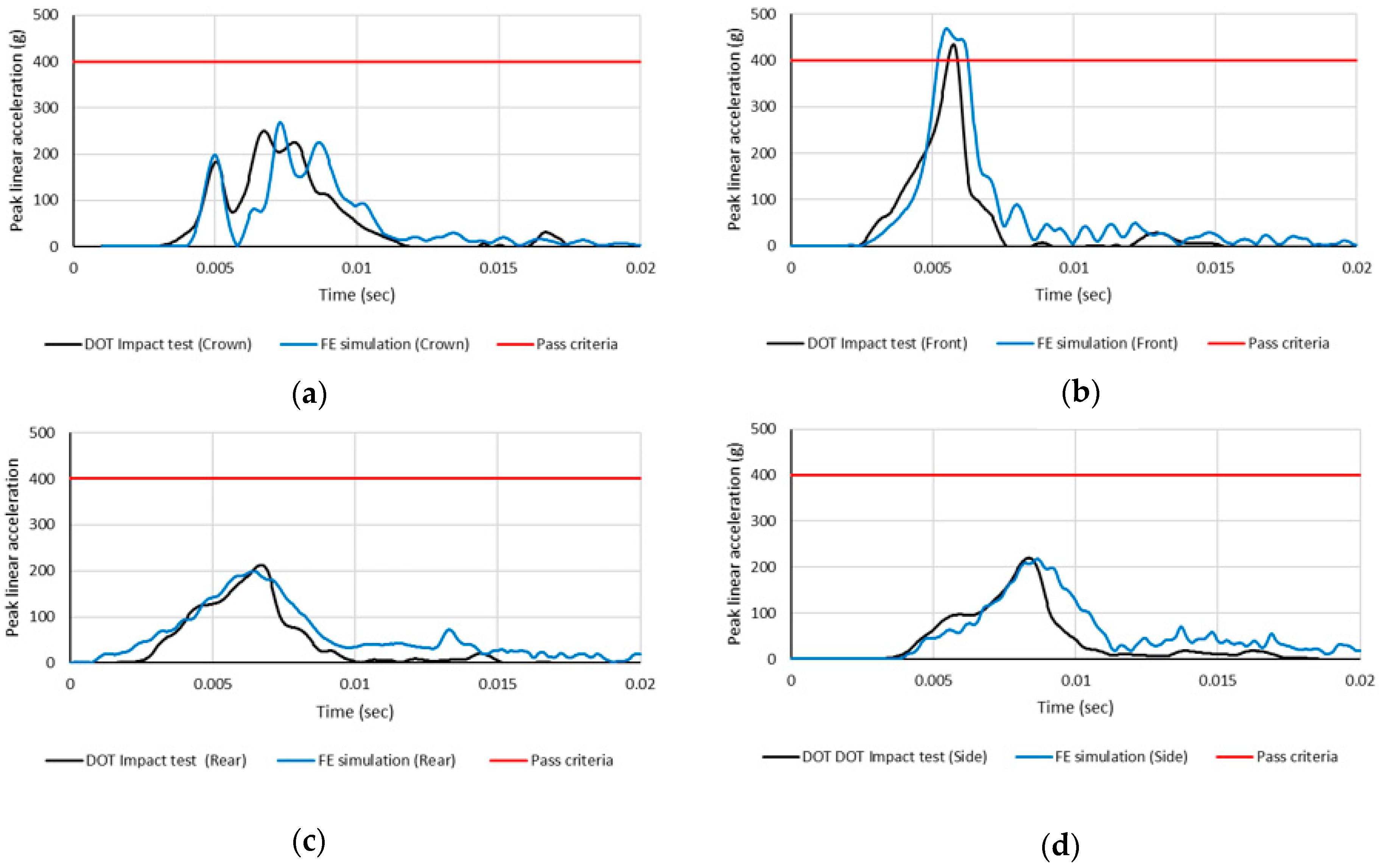
3.1. Finite Element Model Validation with the DOT FMVSS 218 Drop Test

The head–helmet model was first validated with the DOT drop test results of Prasartong et al. [38]. Comparisons of the linear acceleration obtained from the experiments and the simulations at four impact locations are shown in Figure 7.
The linear acceleration obtained from the simulations showed a slight discrepancy with the experimental results. The highest difference in the peak linear acceleration was at the crown location, with a difference less than 7%. Good agreement with the experimental results in terms of the linear acceleration was achieved. However, the head contact time during the first peak for all impact locations expressed some differences. This is because the head used in the experiment was a rigid headform, while the head model is deformable as a real human head. The larger contact time period led to a 20–25% higher head injury criteria (HIC) value. However, the DOT test adopted the maximum force as a guide to set the peak linear acceleration at 400 g as passed criteria. In addition, the results shows that the peak linear acceleration obtained from the frontal impact was higher than the maximum allowable value of 400 g. This child helmet failed the DOT drop test. The headform used in the experiment cannot measure the rotational acceleration but the deformable head model can provide the rotational acceleration, skull stress and brain strain. The peak values of both linear and rotational accelerations at each impact location are shown in Figure 8. The rotational acceleration is related directly to the concussion and diffuse axonal injury. Margulies et al. [46] proposed that the peak rotational acceleration above 8000 rad/s2 could cause DAI. Zhang et al. [47] also proposed a limit of 7900 rad/ s2 for 80% probability of sustaining a mild traumatic brain injury. The rotational accelerations from the simulations at the front and side impact locations just exceeded 8000 rad/ s2 which implied the risk of mild traumatic brain injury. The safety performance of this child helmet was not acceptable.

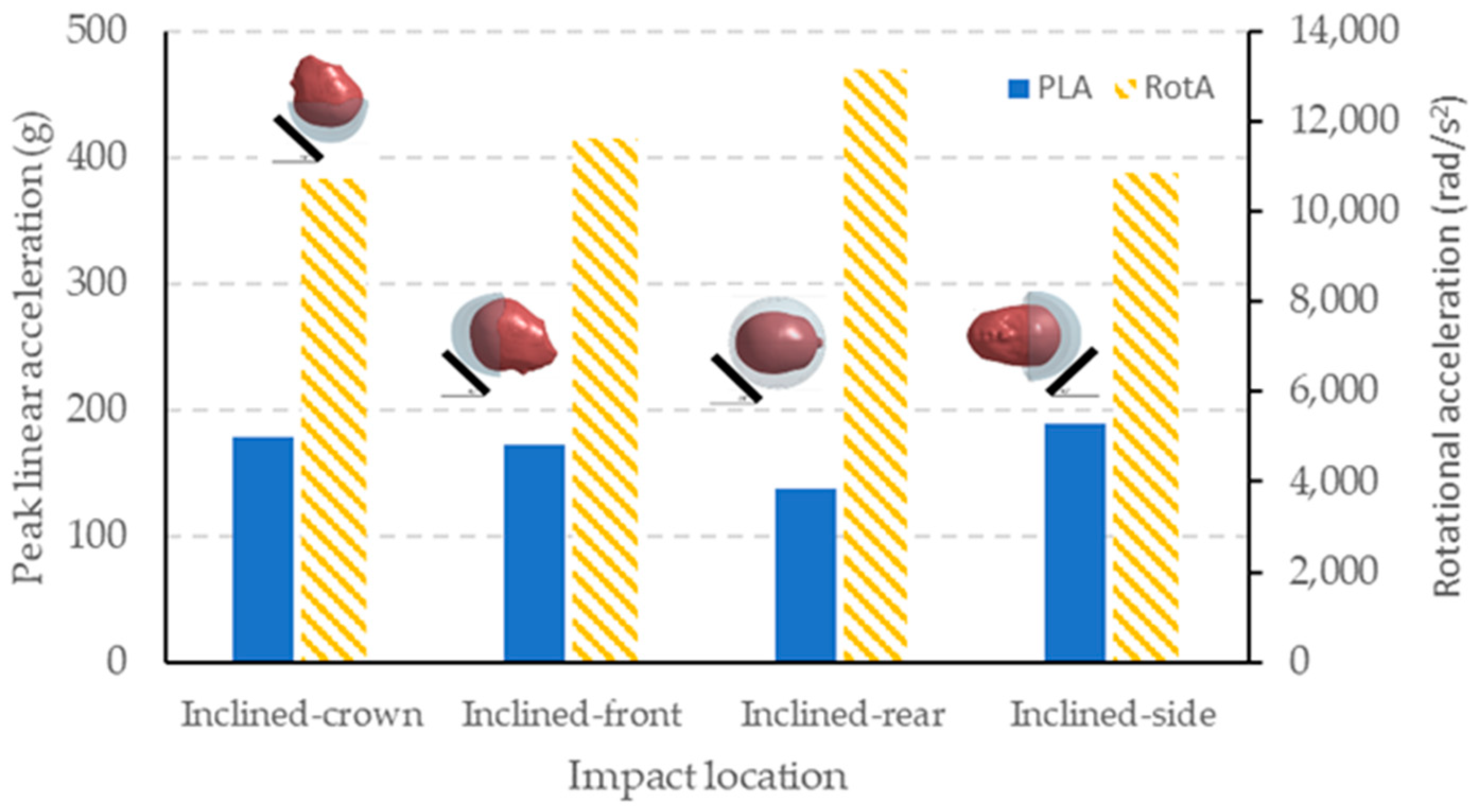
3.2. Simulation Results from the Drop Test with 45° Inclined Flat Anvil

The resultant accelerations were extracted from the node at the C.G. of the 6YO THUMS head. The peak values of both linear and rotational accelerations for each impact location are shown in Figure 9. The peak linear accelerations at all impact locations were below 200 g, while all rotational accelerations were high and above 8000 rad/s2. There was a high risk of mild traumatic brain injury. The inclined flat anvil caused a large rotational acceleration compared to the horizontal anvil. However, the peak linear acceleration was low compared to the DOT drop test.
The maximum principal strain (MPS) of the brain is also another injury measure related to brain concussion and DAI [48]. Figure 10 shows the brain MPS at each impact location. The brain MPS, which exceeded 0.25, implied a high risk of brain DAI [38]. The red area in Figure 10 indicated the brain area with the MPS greater than 0.25. It was found that 55.78% of brain volume experienced a maximum principal strain greater than 0.25 (i.e., CSDM-0.25 = 55.75%) for the rear impact location. This implied a 50% risk of DAI [49]. The results expressed the risk of concussion and DAI in all four location drop tests. These corresponded to the high value of the rotational acceleration, which exceeded the limit of 8000 rad/s2. At the rear impact location, the rotational acceleration was as high as 13,143 rad/s2 and the volume of brain with the MPS greater than 0.25 was also very high. However, the peak linear acceleration at this location was only 137.2 g.
From the simulation results, the DOT drop test provided critical loading conditions for the skull fracture, while the inclined drop tests provided critical loading conditions for brain injury. In the next section, the study of the effect of helmet parameters would consider the peak linear acceleration obtained from the DOT drop test and the rotational acceleration obtained from the inclined anvil drop test.

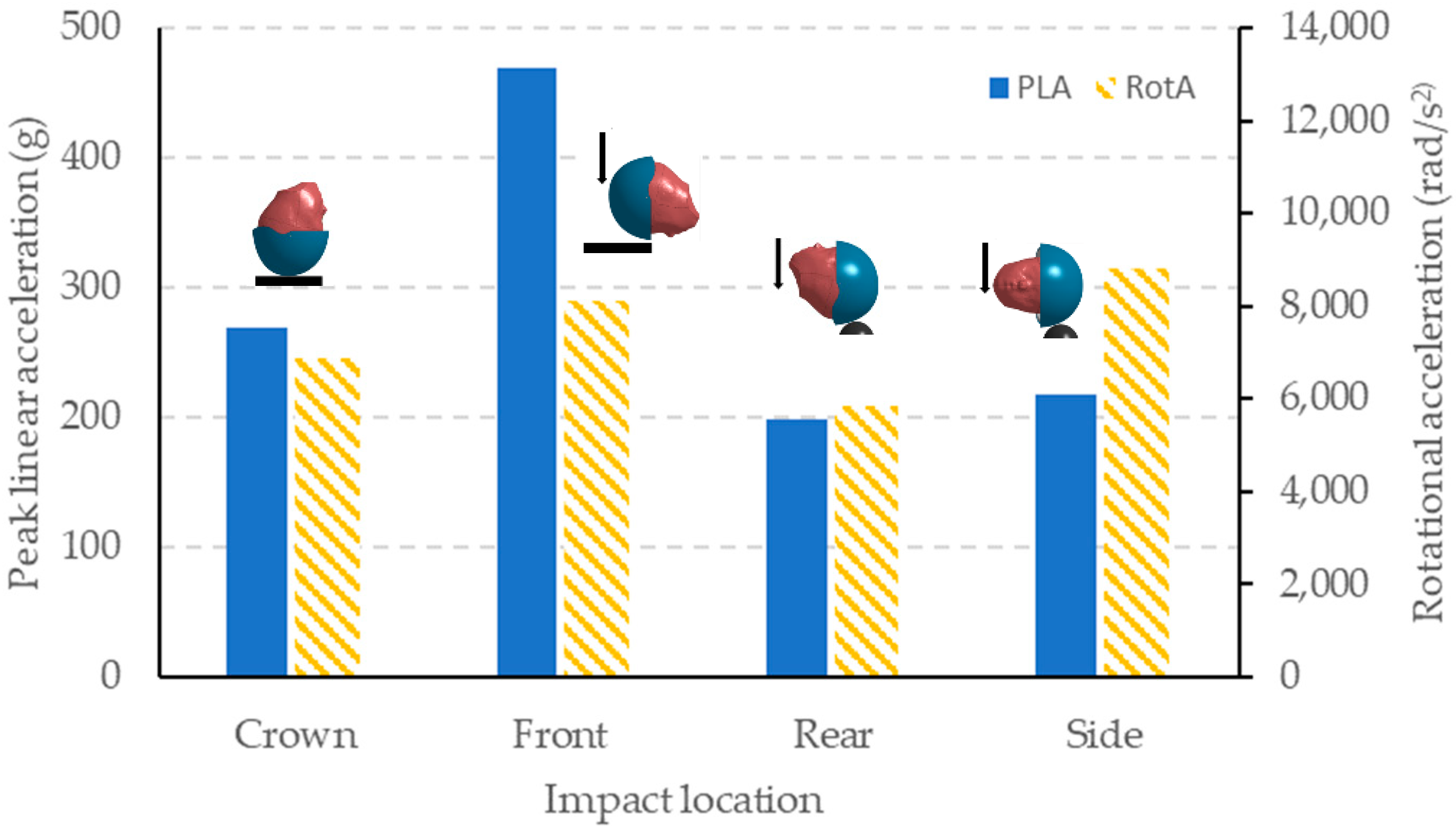
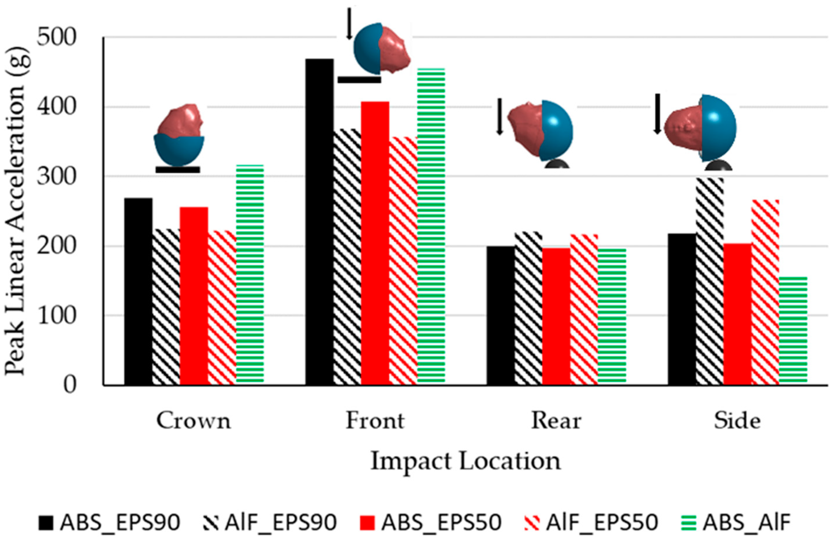
3.3. The Effect of Materials on the Peak Linear Acceleration and the Rotational Acceleration

The original geometry of the child helmet was employed to study the effect of materials. Comparisons of the peak linear acceleration obtained from the DOT drop test are shown in Figure 11 for all five combinations of helmet materials.
For the same density of EPS, it was found that the simulations with the Al-foam outer shell (AlF_EPS90 and AlF_EPS50) showed an 18–20% lower peak linear acceleration than those with ABS outer shell (ABS_EPS90 and ABS_EPS50) at the crown and the front impact locations, while the simulations with ABS outer shell showed a 10% lower peak linear acceleration than those with the Al-foam outer shell at the rear impact location. If the ABS was used, the peak linear acceleration at the side impact location was 30% lower. When comparing the model with the different density of the inner liner EPS, the one with 50 kg/m3 (ABS_EPS50 and AlF_EPS50) expressed a little lower peak linear acceleration compared to EPS 90 kg/m3 (ABS_EPS90 and AlF_EPS90) for both outer shell materials.
The drop tests for the rear and side locations employed the hemisphere anvil. The impact area was localized, hence resulting in localized deformation. ABS usually resists penetration better than Al-foam. The peak linear acceleration was smaller for the helmet with ABS outer shell than the helmet with the Al-foam outer shell. When comparing the inner liner material with ABS outer shell, it was found that the Al-foam inner liner showed a much lower peak linear acceleration at the side location only.
Figure 12 shows comparisons of the rotational acceleration obtained from two different outer shell materials, ABS and Al-foam. The simulations with ABS outer shell showed a 7% lower rotational acceleration than those with the Al-foam outer shell only at the inclined-crown location. The simulations with the Al-foam outer shell a expressed significantly lower rotational acceleration at the other impact locations. The simulations with ABS outer shell expressed the rotational acceleration more than 8000 rad/s2 threshold at all impact locations. The 50 kg/m3 density EPS liner showed to a slightly lower rotational acceleration than the 90 kg/m3 EPS. It can be seen that the inner liner with 50 kg/m3 showed a lower peak linear acceleration and rotational acceleration, while the Al-foam outer shell showed a lower peak linear acceleration and a rotational acceleration in most of impact locations. The Al-foam outer shell with 50 kg/m3 EPS liner was selected for later parametric studies.

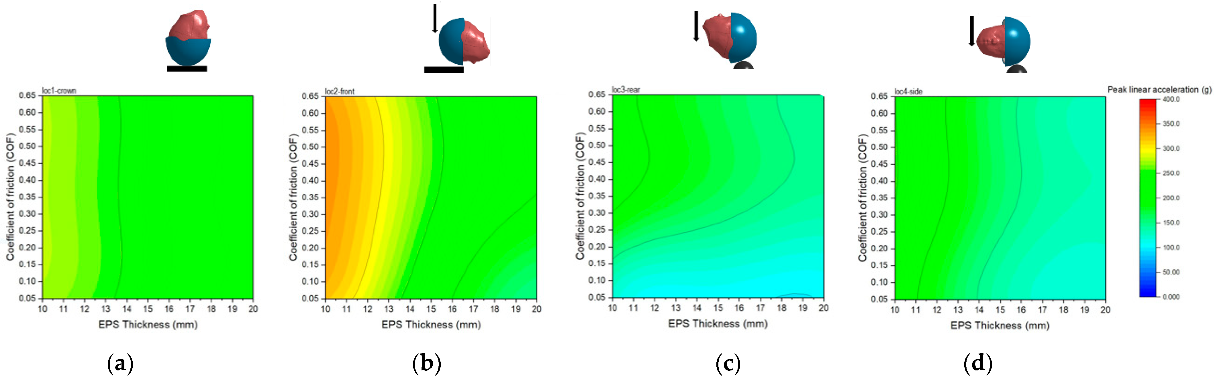
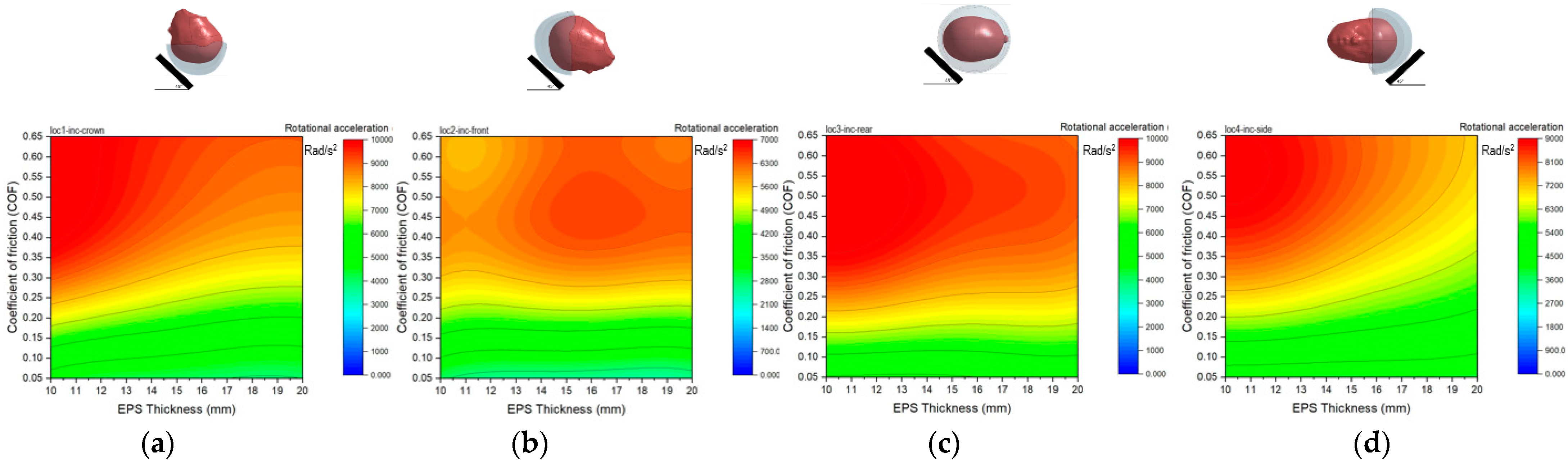
3.4. Effects of Liner Thickness and Head–Helmet Friction

The modified helmet was used to study the effect of the liner thickness and head–helmet friction. The work employed the POD and Kriging method to obtain a reduced-order model using the training data from finite element simulations. Nine training data were required for each impact locations. The peak linear acceleration was extracted from the DOT FMVSS 218 drop test, while the rotational acceleration was extracted from the inclined flat anvil drop test. Table 4 illustrates the training data obtained from finite element simulation for the establishment of two ROMs.
Two ROMs were established to predict the linear and rotational accelerations and validated against the finite element simulations. Figure 13 shows comparisons of finite element calculation and the prediction from the ROMs for various impact locations, liner thickness, and the friction coefficient as stated in Table 3. The prediction errors for both linear and rotational accelerations were within ±5% corridor.
The ROMs for the helmet drop test were employed to predict the peak linear acceleration and the rotational acceleration for a helmet with the inner liner thickness ranging from 10 to 20 mm and the head–helmet friction coefficient ranging from 0.05 to 0.65. The prediction results are shown in Figure 14 and Figure 15. The peak linear acceleration decreased with the increasing of the liner thickness for all impact locations. However, at the range of 17–20 mm thickness, the peak linear acceleration changed insignificantly with thickness for all friction coefficients. The peak linear acceleration hardly increased with the friction coefficient. The effect of the friction coefficient on the peak linear acceleration was more obvious at the front and the rear locations than the others. All predicted cases gave the peak linear acceleration lower than the 400 g criteria as stated in the DOT FMVSS 218.
The peak rotational acceleration increased with the friction coefficient for all impact locations, as shown in Figure 15. It slightly decreased with increasing of the liner thickness. However, for the friction coefficient below 0.2, the liner thickness hardly affected the peak rotational acceleration for all impact locations. Similar trend was observed apart from the one at the front impact location. With the rotational acceleration criteria of 8000 rad/s2 [31], the suggested ranges of both helmet parameters are presented in Table 5.
For the crown location, the maximum allowable head–helmet friction coefficient was 0.36 with the liner thickness greater than 17 mm. For a liner thickness of 10 mm, the friction coefficient must be 0.23 or lower. The friction coefficient could be as high as 0.65 for the side location but the thickness must be greater than 16 mm. However, the critical location was the rear location—the maximum friction coefficient was allowed to be 0.27 and the thickness must be greater than 18 mm to maintain the rotational acceleration within 8000 rad/s2.

4. Discussion

A commercial child helmet was modelled and validated with the DOT drop test experiment. This child helmet safety performance was not acceptable due to the peak linear acceleration exceeding 400 g at the front location. All existing helmet test standards have not yet assessed according to the head rotational acceleration which can induce brain injury. Although the peak linear acceleration was low, but the head rotational acceleration can be high as found at the side impact location where the peak linear acceleration was only 220 g, but the rotational acceleration was above 8000 rad/s2. These implied a high risk of brain concussion. In addition, the most common type of head impacts in a motorcycle crash is the oblique impact which induces a high head rotational acceleration [5]. The drop test of the head–helmet on the inclined flat anvil well represented the oblique impact. The head rotational acceleration resulting from the inclined anvil drop tests was very high (above 10,000 rad/s2) in all four impact locations. However, the peak linear accelerations were below 200 g. The maximum principal strain of the brain also exceeded 0.25 which implied a high risk of DAI [33]. This MPS value showed a good correlation with the high value of the rotational acceleration. This case is a good example of the condition that could lead to brain injury without the risk of skull fracture. The results emphasized that the existing child helmet was not able to effectively protect child head-brain injury. High energy absorption and head rotation reduction capabilities as well as be lightweight are required for the safety of a child helmet. Al-foam was introduced to the helmet outer shell and inner liner. It showed overall better performance in terms of the peak linear and rotational accelerations with a much lighter weight than the one with ABS when used as the outer shell. In addition, the corresponding peak linear acceleration obtained from the front impact location was reduced below 400 g when applying Al-foam as outer shell. The porous structure of Al-foam enhanced an energy absorption capability as well as reducing the head–helmet sliding motion. However, the thin layer of ABS still needed for penetration resistance. Applying Al-foam as the inner liner showed some higher linear and rotational accelerations when compared to the EPS 50 kg/m3 in most impact locations. The EPS density did not significantly affect the rotational acceleration.
The inner liner thickness and the friction between the helmet and head were also considered as helmet design parameters. They affected the peak linear acceleration and the rotational acceleration of the head. The results showed that the head–helmet friction had slight effect on the peak linear acceleration, while it was affected more by the thickness of the liner. The larger the liner thickness, the lower the peak linear and rotational accelerations were. Oppositely, the head–helmet friction coefficient significantly affected the rotational acceleration. Low friction allowed the helmet and head to slide during impact, hence the reduction in the rotational acceleration. The results showed that the impact locations also affected the acceleration since different impact locations led to different head motions. The results revealed that the rear impact location was critical for the rotational acceleration. If the coefficient of friction was greater than 0.27 the rotational acceleration would go beyond 8000 rad/s2 for the entire range of the liner thickness. It was found if the friction coefficient below 0.2, the liner thickness had no influence on the rotational acceleration in all impact locations. Hence, the liner thickness could be reduced to 10 mm. Non-uniform liner thickness could enhance weight reduction. The weight of the optimum helmet was 0.143 kg, which was 60% less than the baseline original one with much better safety performance.
In addition, this paper also demonstrated the use of a model reduction technique which significantly benefit the parametric studies in design and optimization. The predictive model was established based on the POD and the Kriging method. The predictive capability of the reduced-order model was good and the calculation time was drastically reduced compared to the corresponding finite element simulation. The discrepancy was within ±5%. With a wide range of helmet parameters, the linear and rotational accelerations of 5124 cases were predicted within 20 min. The optimization process could be performed effectively with a large amount of data.
The presented study has the following limitations. The head–helmet finite element model was only validated against the DOT drop test. It has not yet been validated against the 45° inclined drop test. Strain-based injury metrics are desirable for assessing brain injury, this study only looked into kinematics-based metrics (acceleration). However, there have been some studies investigating the correlation between head rotation and brain strain measures [23]. Another limitation is that this work only considered the half helmet type, and the results from this study may vary for other helmet types.

5. Conclusions

The main objective of this paper was to investigate the effect of helmet parameters, including materials, the liner thickness and the head–helmet friction on head and brain injury. The investigation processes involved the use of combined finite element simulation and a model reduction technique to produce the reduced-order models which could predict the output responses in a much shorter time than its corresponding finite element simulation.
The commercial child helmet finite element model was validated against the DOT FMVSS 218 experiment. This existing child helmet did not pass due to the high linear acceleration at the front location. In addition, the helmet experienced a high rotational acceleration exceeding the brain injury criteria in all locations when dropping onto the 45° inclined anvil. The results revealed the benefit of using Al-foam as it enhanced the mitigation of the linear and rotational accelerations. The design criteria for the majority of the helmets often consider the peak linear acceleration and HIC, which are related directly to skull fracture. However, the rotational acceleration related to brain injury is rarely taken into account. This study showed that the head–helmet friction coefficient had a significant effect on the head motion, hence the rotational acceleration. The lower the friction, the lower the rotational acceleration. The thickness of the liner mainly affected the peak linear acceleration. A thicker liner could absorb more energy, hence lowering the peak linear acceleration. It was also found that at low friction, i.e., below 0.2, the liner thickness hardly affected the head rotational acceleration. With the use of Al-foam together with EPS foam and low friction between the head–helmet surface, the risk of severe head and brain injury could be reduced. In addition, the weight of the helmet also significantly decreased.

Author Contributions

Conceptualization, J.C.; methodology, J.C.; software, N.P. and J.C.; validation, N.P. and J.C.; formal analysis, N.P. and J.C.; investigation, N.P. and J.C.; resources, J.C.; writing—original draft preparation, N.P. and J.C.; writing—review and editing, J.C.; visualization, J.C.; supervision, J.C.; project administration, J.C.; funding acquisition, J.C. All authors have read and agreed to the published version of the manuscript.

Funding

This research was funded by King Mongkut’s University of Technology North Bangkok grant number KMUTNB-61-GOV-B-39.

Institutional Review Board Statement

Not applicable.

Informed Consent Statement

Not applicable.

Data Availability Statement

Not applicable.

Acknowledgments

The authors gratefully acknowledge the financial support from King Mongkut’s University of Technology North Bangkok (KMUTNB-61-GOV-B-39) and Thailand Toray Science Foundation.

Conflicts of Interest

The authors declare no conflict of interest.

References

  1. World Health Organization. Global Status Report on Road Safety 2018; World Health Organization: Geneva, Switzerland, 2018. [Google Scholar]
  2. Koetniyom, S.; Carmai, J.; Kassim, K.A.A.; Ahmad, Y. Kinematics and Injury Analysis of Front and Rear Child Pillion Passenger in Motorcycle Crash. Int. J. Automot. Mech. Eng. 2018, 15, 5522–5534. [Google Scholar] [CrossRef] [Green Version]
  3. Carmai, J.; Koetniyom, S.; Sungduang, W.; Abu Kassim, K.; Ahmad, Y. Motorcycle Accident Scenarios and Post-Crash Kinematics of Motorcyclists in Thailand. J. Soc. Automot. Eng. Malays. 2018, 2, 231–244. [Google Scholar] [CrossRef]
  4. Sudyoddee, H.; Behr, M.; Llari, M.; Koetniyom, S.; Carmai, J. Investigation of motorcyclist and pillion passenger injuries using numerical simulations. IOP Conf. Ser. Mater. Sci. Eng. 2019, 501, 012009. [Google Scholar] [CrossRef]
  5. Carmai, J.; Koetniyom, S.; Hossain, W. Analysis of rider and child pillion passenger kinematics along with injury mechanisms during motorcycle crash. Traffic Inj. Prev. 2019, 20, S1, S13–S20. [Google Scholar] [CrossRef] [Green Version]
  6. Jensupakarn, A.; Kantipong, K. Influence of motorcycle rider and driver characteristics and road environment on red light running behaviour at signalized intersections. Accid. Anal. Prev. 2018, 113, 317–324. [Google Scholar] [CrossRef]
  7. Uttra, S.; Jomnonkwao, S.; Watthanaklang, V.; Ratanavaraha, V. Development of self-assessment indicators for motorcycle riders in Thailand: Application of the motorcycle rider behaviour questionnaire (MRBQ). Sustainability 2020, 12, 2785. [Google Scholar] [CrossRef] [Green Version]
  8. Champahom, T.; Jomnonkwao, S.; Satiennam, T.; Suesat, N.; Ratanavaraha, V. Modeling of safety helmet use intention among students in urban and rural Thailand based on the theory of planned behaviour and locus of control. Soc. Sci. J. 2020, 57, 508–529. [Google Scholar]
  9. Jomnonkwao, S.; Watthanaklang, D.; Sangphong, O.; Champahom, T.; Laddawan, N.; Uttra, S.; Ratanavaraha, V.A. Comparison of Motorcycle Helmet Wearing Intention and Behavior between Urban and Rural Areas. Sustainability 2020, 12, 8395. [Google Scholar] [CrossRef]
  10. Champahom, T.; Wisutw, P.; Chanpariyavatevong, K.; Laddawan, N.; Jomnonkwao, S.; Ratanavaraha, V. Factors affecting severity of motorcycle accidents on Thailand’s arterial roads: Multiple correspondence analysis and ordered logistics regression approaches. IATSS Res. 2021, 46, 101–111. [Google Scholar] [CrossRef]
  11. Vajari, M.A.; Aghabayk, K.; Sadeghian, M.; Shiwakoti, N. A multinomial logit model of motorcycle crashes using random parameters. J. Sef. Res. 2020, 73, 17–24. [Google Scholar] [CrossRef]
  12. Farid, A.; Ksaibati, K. Modeling severities of motorcycle crashes using random parameters. J. Traffic Transp. Eng. 2020, 8, 225–236. [Google Scholar] [CrossRef]
  13. Chang, F.; Xu, P.; Zhou, H.; Lee, J.; Huang, H. Identifying motorcycle high risk traffic scenarios through interactive analysis of driver behaviour and traffic characteristics. Transp. Res. Part F 2019, 62, 844–854. [Google Scholar] [CrossRef]
  14. Save the Children Thailand 2014 The 7% Project. Available online: https://thailand.savethechildren.net/news/save-childrens-7-project-presents-helmet-heroes (accessed on 6 December 2019).
  15. Kreykes, N.S.; Letton, R.W. Current issues in the diagnosis of pediatric cervical spine injury. Semin. Pediatr. Surg. 2010, 19, 257–264. [Google Scholar] [CrossRef] [PubMed] [Green Version]
  16. Bourdet, N.; Mojumder, S.; Piantini, S.; Deck, C.; Pierini, M.; Willinger, R. Proposal of a new motorcycle helmet test method for tangential impact. In Proceedings of the IRCOBI Conference, Málaga, Spain, 14–16 September 2016; pp. 479–489. [Google Scholar]
  17. Davidsson, J.; Angeria, M.; Risling, M. Injury threshold for sagittal plane rotational induced diffuse axonal injuries. In Proceedings of the IRCOBI conference, York, UK, 9–11 September 2009; p. 43. [Google Scholar]
  18. Kleiven, S. Why Most Traumatic Brain Injuries Are Not Caused by Linear Acceleration but Skull Fractures are. Front. Bioeng. Biotechnol. 2013, 1, 15. [Google Scholar] [CrossRef] [PubMed] [Green Version]
  19. Ommaya, A.K.; Gennarelli, T.A. Cerebral Concussion and Traumatic Unconsciousness. Brain 1974, 7, 633–654. [Google Scholar] [CrossRef] [PubMed] [Green Version]
  20. Gennarelli, T.A.; Thibault, L.E. Biomechanics of Acute Subdural Hematoma. J. Trauma Inj. Infect. Crit. Care 1982, 22, 680–686. [Google Scholar] [CrossRef] [PubMed]
  21. Gennarelli, T.A.; ScD, L.E.T.; Adams, J.H.; Graham, D.I.; Thompson, C.J.; Marcincin, R.P. Diffuse axonal injury and traumatic coma in the primate. Ann. Neurol. 1982, 12, 564–574. [Google Scholar] [CrossRef] [PubMed]
  22. Ashby, M.F.; Flecks, N.A.; Evans, A.G.; Gibson, L.J.; Hutchinson, J.W.A.; Wadley, H.N.G. (Eds.) Properties of metal foams. In Metal Foams: A Design Guide, 1st ed.; Butterworth-Heinemann: London, UK, 2000. [Google Scholar]
  23. Cymat Technologies Ltd. Aluminium Foam Technology Applied to Automotive Design; CYMAT: Toronto, ON, Canada, 2005. [Google Scholar]
  24. Mills, N.; Wilkes, S.; Derler, S.; Flisch, A. FEA of oblique impact tests on a motorcycle helmet. Int. J. Impact Eng. 2009, 36, 913–925. [Google Scholar] [CrossRef] [Green Version]
  25. Bonugli, E.; Cormier, J.; Reilly, M.; Reinhart, L. Replicating Real-World Friction of Motorcycle Helmet Impacts and Its Effects on Head Injury Metrics; SAE Technical Paper 2017-01-1433; SAE International: Warrendale, PA, USA, 2017. [Google Scholar]
  26. Finan, J.D.; Nightingale, R.W.; Myers, B.S. The Influence of Reduced Friction on Head Injury Metrics in Helmeted Head Impacts. Traffic Inj. Prev. 2008, 9, 483–488. [Google Scholar] [CrossRef]
  27. Meng, S.; Cernicchi, A.; Kleiven, S.; Halldin, P. High-speed helmeted head impacts in motorcycling: A computational study. Accid. Anal. Prev. 2019, 134, 105297. [Google Scholar] [CrossRef]
  28. Ebrahimi, I.; Golnaraghi, F.; Wang, G.G. Factors Influencing the Oblique Impact Test of Motorcycle Helmets. Traffic Inj. Prev. 2015, 16, 404–408. [Google Scholar] [CrossRef]
  29. Juste-Lorente, Ó.; Maza, M.; Piccand, M.; López-Valdés, F.J. The Influence of headform/helmet friction on head Impact Bio-mechanics in Oblique Impacts at Different Tangential Velocities. Appl. Sci. 2021, 11, 11318. [Google Scholar] [CrossRef]
  30. Elkin, B.S.; Elliott, J.M.; Siegmund, G.P. Whiplash Injury or Concussion? A Possible Biomechanical Explanation for Concussion Symptoms in Some Individuals Following a Rear-End Collision. J. Orthop. Sports Phys. Ther. 2016, 46, 874–885. [Google Scholar] [CrossRef] [Green Version]
  31. Kelkar, R.; Hasija, V.; Takhounts, E.G. Effect of anular acceleration on brain injury metric. In Proceedings of the IRCOBI conference, Munich, Germany, 8–11 September 2020; pp. 552–568. [Google Scholar]
  32. Bain, K.; Mao, H. Mechanisms and variances of rotation-induced brain injury: A parametric investigation between head kinematics and brain strain. Biomech. Model. Mechanobiol. 2020, 19, 2323–2341. [Google Scholar] [CrossRef]
  33. Gabler, L.F.; Crandall, J.R.; Panzer, M.B. Assessment of Kinematic Brain Injury Metrics for Predicting Strain Responses in Diverse Automotive Impact Conditions. Ann. Biomed. Eng. 2016, 44, 3705–3718. [Google Scholar] [CrossRef]
  34. Livermore Software Technology Corporation (LSTC). LS-DYNA Keyword User’s Manual. 2007; Volume 1 Version 971. Available online: https://www.dynasupport.com/manuals/ls-dyna-manuals (accessed on 13 September 2020).
  35. Fernandes, F.A.; Alves de Sousa, R.J.; Willinger, R.; Deck, C. Finite Element Analysis of Helmeted Impacts and Head Injury Evaluation with a Commercial Road Helmet. In Proceedings of the IRCOBI Conference, Gothenburg, Sweden, 11–13 September 2013; pp. 431–442. [Google Scholar]
  36. Pinnoji, P.; Mahajan, P.; Bourdet, N.; Deck, C.; Willinger, R. Impact dynamics of metal foam shells for motorcycle helmets: Experiments & numerical modeling. Int. J. Impact Eng. 2010, 37, 274–284. [Google Scholar] [CrossRef]
  37. Loyd, A.M. Studies of the Human Head from Neonate to Adult: An Inertial, Geometrical and Structural Analysis with Comparisons to the ATD Head. PhD Thesis, Duke University, Durham, NC, USA, 2011. [Google Scholar]
  38. Department for Transportation. Federal Motor Vehicle Safety Standard (FMVSS) No. 218; Department for Transportation: Washington, DC, USA, 2015. [Google Scholar]
  39. Prasartthong, N.; Koetniyom, S.; Carmai, J. Development of Motorcycle helmet for pre-school Children Using Metal Foam. IOP Conf. Ser. Mate. Sci. Eng. 2019, 501, 012018. [Google Scholar] [CrossRef]
  40. Kleiven, S. Predictors for Traumatic Brain Injuries Evaluated through Accident Reconstructions. Stapp. Car Crash J. 2007, 51, 81–114. [Google Scholar] [CrossRef]
  41. Ghajari, M.; Peldschus, S.; Galvanetto, U.; Iannucci, L. Effects of the presence of the body in helmet oblique impacts. Accid. Anal. Prev. 2013, 50, 263–271. [Google Scholar] [CrossRef]
  42. Caserta, G.D.; Iannucci, L.; Galvanetto, U. Shock absorption performance of a motorbike helmet with honeycomb reinforced liner. Compos. Struct. 2011, 93, 2748–2759. [Google Scholar] [CrossRef]
  43. Hsieh, C.-H.; Hsu, S.-Y.; Tsai, C.-H.; Huang, C.-Y.; Hsieh, T.-M.; Chou, S.-E.; Su, W.-T. Association between types of helmet and outcomes in motorcyclists after traffic accidents. Formos. J. Surg. 2021, 54, 205. [Google Scholar] [CrossRef]
  44. Kayvantash, K. Model Reduction Techniques for On-Board and Parametric Crash and Safety Simulations; LS-DYNA Forum: Bamberg, Germany, 2018. [Google Scholar]
  45. Hexagon. ODYSSEE (Quasar/Lunar) Software Package for Machine Learning, Model Fusion, Forecasting. Available online: https://www.mscsoftware.com/product/odyssee (accessed on 13 April 2022).
  46. Margulies, S.S.; Thibault, L.E. A proposed tolerance criterion for diffuse axonal injury in man. J. Biomech. 1992, 25, 917–923. [Google Scholar] [CrossRef]
  47. Zhang, L.; Yang, K.H.; King, A.I. A Proposed Injury Threshold for Mild Traumatic Brain Injury. J. Biomech. Eng. 2004, 126, 226–236. [Google Scholar] [CrossRef] [PubMed]
  48. Bain, A.C.; Meaney, D.F. Tissue-Level Thresholds for Axonal Damage in an Experimental Model of Central Nervous System White Matter Injury. J. Biomech. Eng. 2000, 122, 615–622. [Google Scholar] [CrossRef] [Green Version]
  49. Takhounts, E.G.; Ridella, S.A.; Hasija, V.; Tannous, R.E.; Campbell, J.Q.; Malone, D.; Danelson, K.; Stizel, J.; Rowson, S.; Duma, S. Investigation of Traumatic Brain Injuries Using the Next Generation of Simulated Injury Monitor (SIMon) Finite Element Head Model. Stapp. Car Crash J. 2008, 52, 1–31. [Google Scholar]
Figure 1. (a) A child motorcycle helmet sold in Thailand (b) the half section of the inner liner.
Applsci 12 08016 g001
Figure 2. A 6-year-old child human body head model with the location of C.G.
Applsci 12 08016 g002
Figure 3. Model setup for the DOT drop test at (a) crown, (b) front, (c) rear, and (d) side locations.
Applsci 12 08016 g003
Figure 4. Model setup for the 45° inclined drop test at (a) crown, (b) front, (c) rear, and (d) side.
Applsci 12 08016 g004
Figure 5. The modified child helmet with uniform liner thickness.
Applsci 12 08016 g005
Figure 6. Reduced-order model establishment process.
Applsci 12 08016 g006
Figure 7. Comparisons of the linear acceleration obtained from the DOT drop test and the finite element simulations at (a) crown, (b) front, (c) rear, and (d) side impact locations.
Applsci 12 08016 g007
Figure 8. The peak linear (PLA) and the rotational accelerations (RotA) obtained from the DOT drop tests at four impact locations.
Applsci 12 08016 g008
Figure 9. The peak linear (PLA) and the rotational accelerations (RotA) obtained from the inclined drop tests at four impact locations.
Applsci 12 08016 g009
Figure 10. Maximum principal strain on the brain obtained from the inclined drop tests at (a) crown, (b) front, (c) rear, and (d) side locations.
Applsci 12 08016 g010
Figure 11. Comparisons of the peak linear acceleration obtained from the DOT drop test for five combinations of helmet material.
Applsci 12 08016 g011
Figure 12. Comparisons of the peak rotational acceleration obtained from the inclined anvil drop test for five combinations of helmet material.
Applsci 12 08016 g012
Figure 13. Scatter plots of prediction errors for both a peak (a) linear acceleration and a (b) rotational acceleration.
Applsci 12 08016 g013
Figure 14. Relationship between helmet parameters and the peak linear acceleration predicted by the ROM with the DOT drop test at (a) crown, (b) front, (c) rear, and (d) side impact locations.
Applsci 12 08016 g014
Figure 15. Relationship between helmet parameters and the rotational acceleration predicted by the ROM with the inclined anvil drop test at (a) crown, (b) front, (c) rear, and (d) side impact locations.
Applsci 12 08016 g015
Table 1. Helmet model with various combination of materials.
Model NameOuter Shell MaterialInner Liner MaterialWeight (kg)
ABS_EPS90ABSEPS 90 kg/m30.346
ABS_EPS50ABSEPS 50 kg/m30.317
ALF_EPS90Al-foamEPS 90 kg/m30.103
ALF_EPS50Al-foamEPS 50 kg/m30.073
ABS_ALFABSAl-foam0.413
Table 2. Model setup to generate training data.
Model No.123456789
Liner thickness (mm)101010151515202020
Head–helmet friction coefficient (µ)0.650.350.050.650.350.050.650.350.05
Weight (kg)0.1430.1750.231
Table 3. Model setup for validation data.
Impact LocationFrontSideCrownRearCrownFrontRearSideCrownSideFrontRear
Thickness (mm)101010101515151520202020
Friction coefficient0.20.20.50.50.20.20.50.50.20.20.50.5
Table 4. Finite element simulation results for a ROM training data.
Inner Liner
Thickness
Head–Helmet Friction CoefficientPeak Linear
Acceleration(g)
Rotational Acceleration (rad/s2)
CrownFrontRearSideIncl-CrownIncl-FrontIncl-RearIncl-Side
10 mm0.65287.5339.1216.7259.712,1616738.510,3128904.3
10 mm0.35285.9347210.4258.710,9096821.19888.57971.8
10 mm0.05278.5324.9124.8234.46025.54564.35769.94281.9
15 mm0.65254.9252.9169.9158.910,8857035.39336.47830.4
15 mm0.35253.8252.4167.3158.39370.16763.590877052.1
15 mm0.05251.6217.4108.1138.45511.63919.45598.64198.3
20 mm0.65243.9198.5145.4133.311,1606798.99200.67035
20 mm0.35243.3196.8141.9132.39479.87059.18818.96204
20 mm0.05248.7152.2100.9126.95184.94047.26160.24188.2
Table 5. Suggested ranges of a suitable friction coefficient and liner thickness.
Impact LocationHead–Helmet Friction Coefficient (µ)Liner Thickness (Th)
Inclined-crownµ ≤ 0.23Th ≥ 10 mm
0.23 < µ ≤ 0.28Th ≥ 13 mm
0.28 < µ ≤ 0.33Th ≥ 15 mm
0.33 < µ ≤ 0.36Th ≥ 17 mm
Inclined-frontµ ≤ 0.65Th ≥ 10 mm
Inclined-rearµ ≤ 0.21Th ≥ 10 mm
0.21< µ ≤ 0.23Th ≥ 13 mm
0.23< µ ≤ 0.25Th ≥ 15 mm
0.25< µ ≤ 0.27Th ≥ 18 mm
Inclined-sideµ ≤ 0.33Th ≥ 10 mm
0.33< µ≤ 0.4Th ≥ 13 mm
0.4 < µ ≤ 0.5Th ≥ 15 mm
0.4 < µ ≤ 0.65Th ≥ 16 mm
Publisher’s Note: MDPI stays neutral with regard to jurisdictional claims in published maps and institutional affiliations.

