Article

BDS/IMU Integrated Auto-Navigation System of Orchard Spraying Robot

1
School of Mechanical and Electrical Engineering, Hunan Agricultural University, Changsha 410128, China
2
Hunan Agricultural Equipment Institute, Hunan Academy of Agricultural Sciences, Changsha 410125, China
3
School of Information and Intelligence, Hunan Agricultural University, Changsha 410128, China
*
Authors to whom correspondence should be addressed.
Appl. Sci. 2022, 12(16), 8173; https://doi.org/10.3390/app12168173
Submission received: 12 July 2022 / Revised: 10 August 2022 / Accepted: 11 August 2022 / Published: 16 August 2022
(This article belongs to the Section Agricultural Science and Technology)

Abstract

:

Featured Application

Authors are encouraged to provide a concise description of the specific application or a potential application of the work. This section is not mandatory.

Abstract

To improve the accuracy and reliability of orchard spraying robots, an integrated navigation system was developed, consisting of a real-time kinematic positioning-Beidou satellite navigation system (RTK-BDS) receiver, an inertial measurement unit (IMU), a navigation controller, and servo motors. Using the loose coupling combination method, an error Kalman filter algorithm based on the measurement of position and heading angle is implemented to correct the error of the inertial measurement unit in real time. Combining the kinematics model and the pure pursuit model of the spraying robot, a path-tracking control algorithm is proposed. Path planning was conducted according to the terrain characteristics of orchards. Field experiments were carried out on a spraying robot to evaluate the proposed auto-navigation system. The results showed that when the spraying robot was static, the positioning performances of BDS alone and that of the BDS/IMU combined system were similar, the positioning error was less than 1.5 cm, and the heading angle errors were within 0.3°; when the spraying robot moving alone to a straight line at the speed of 0.4 m/s, the position error of the navigation system only using BDS was less than 5.29 cm, the heading angle error was within 3°, while the position error of BDS/IMU integrated navigation system was less than 2.49 cm, and the heading angle error was within 2°. The accuracy of BDS/IMU integrated navigation system is significantly improved. When the orchard spraying robot was moving at the speed of 0.4 m/s, the maximum offset error was lower than 10.77 cm, the average offset error was not higher than 3.55 cm, and the root mean square error (RMSE) of the lateral deviation was 1.19 cm. The results showed that the proposed auto-navigation system could make the spraying robot track the pre-set path smoothly and stably.

1. Introduction

The processes of orchard planting, management, and fruit harvesting in China are confronted with the problems of a low degree of mechanization, high labor intensity, and high cost [1]. Pest control is one of the most important links in the fruit production, performed by spraying pesticides 8~15 times a year, accounting for around 30% of the whole workload in the orchard management [2,3]. Recently, some automatic controlled orchard spraying robots have been developed to reduce the labor intensity and improve efficiency. The navigation system, including positioning and calculating paths, is an important part of the control system of orchard spraying robots.
With the development of navigation and positioning systems [4], technologies such as laser navigation [5,6,7], visual navigation [8,9,10] and Global Navigation Satellite System (GNSS) navigation [11,12] have become research hotspots.
Barawid Jr et al. [13] used the Hough transform algorithm to recognize the tree rows using a laser scanner as a navigation sensor, and the results performed on a tractor show that the lateral error was 0.11 m and the heading error was 1.5°. Thanpattranon et al. [14] developed a navigation system based on a laser rangefinder for a trailer whose moving direction is controlled by a sliding hitch bar, and its RMS difference was 0.275 m. Ai Changsheng et al. [15] proposed an algorithm for the lidar data obtained in the orchard, where a multi-support-vector proportion weighting method is developed to identify the ridge line of vineyards with the average angular deviation of 0.72°. The visual navigation technology, featured with wide range of detection and good cost-efficiency, is one of the mainstream navigation methods [16]. Han Zhenhao et al. [17] proposed a visual navigation method based on U-Net for path recognition, the average pixel error was 9.5 pixels, but this method is only applicable to orchards with visually explicit crop and road edges. Li Wenyang et al. [18] built a navigation system utilizing the film on the single row ridge as the navigation feature, extracted the H channel in HSV colour space, combined with the Otsu algorithm to extract the row ridge, and fitted the navigation line with the least square method. Wang Yi et al. [19] proposed a method to extract citrus trunks based on YOLO V3 convolutional neural network, where the intersections of the trunks and ground were fitted into a navigation line by the least square method. Ma Chi et al. [20] proposed a navigation mark generation method to replace the root point of the fruit tree, where the base point coordinates were extracted from the tree rows based on the cubic spline interpolation method, and the navigation line was generated according to the least square method. Radcliffe et al. [21] fitted the navigation line according to the boundary line between the canopy and the sky, the root mean square error of the horizontal deviation was 2.13 cm when testing in a peach orchard, but this method is only suitable for those kinds of orchards having tree crowns all year round. Branches overhang interferes with the extraction of the boundary line, resulting in a reduction in navigation accuracy. With the development of satellite positioning technology, the error of carrier-phase differential satellite positioning is limited to a few centimeters, on which a lot of agricultural navigation systems were built. Lou Xiwen et al. [22] developed a navigation controller for tractor linear tracking based on a PID controller and Dongfanghong X-804 tractor, using RTK-DGPS positioning technology and combining tractor motion with a hydraulic steering control model. Nagasaka et al. [23] developed a navigation controller for rice transplanting based on RTK-GPS and fiber optic gyroscope sensors to measure position and direction, using actuators to control steering, engine throttle, clutch, brake, etc, where the maximum deviation from the desired path is less than 12 cm. In order to adapt to the orchard, Xiong bin et al. [24] designed an automatic navigation system of orchard sprayer based on RTK-BDS, and built a closed-loop control of steering angle based on steering controller, electric pneumatic steering system and three-axis magnetometer. The field tests showed the maximum offset error was not over 0.13 m for the straight tracking at the speed of 2 km/h.
However, in unstructured orchards, the terrain, illumination, and climate are complicated, which limits the performance of the orchard navigation system built on such technologies as laser, computer vision, or GNSS. In addition, processing lidar data consumes lots of computing power, and it is also difficult to extract navigation features [25]; computer vision is severely affected by ambient lighting and shadows from surrounding plants such as weeds [26]; GNSS is prone to loss signal due to occlusions [27]. To handle those problems, researchers proposed multi-sensor data fusion methods to develop orchard navigation systems [28,29], such as combining BDS and IMU together [30,31], where BDS features high precision, low-cost and good reliability, but it has the problem of losing signals due to interferences from the environment; IMU is isolated from the environment, running with good precision in a short time and generating a high frequency of data, but its error accumulates over time.
In this study, a BDS/IMU integrated navigation algorithm based on the error Kalman filter for position and heading measurement was designed to solve the problems of the unstableness of BDS’s signal and the accumulative errors of IMU’s data. Combined with the advantages of the two, the reliability and accuracy of the navigation system for long-time operation in the orchard were improved. By combining the kinematics model of the spraying robot with the pure tracking model, a path-tracking auto-navigation system was developed. The accuracy and reliability of the system were evaluated in orchard experiments.

2. Materials and Methods

2.1. Overall Design of the System

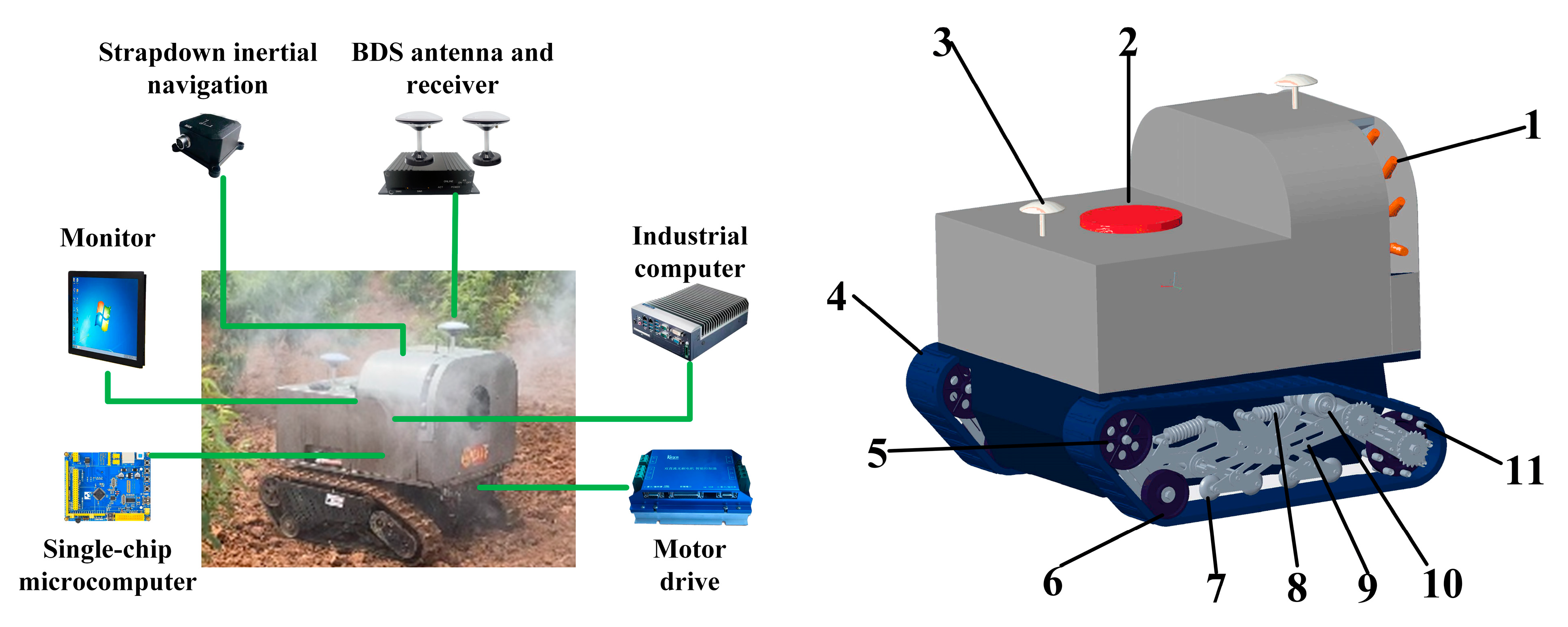
The automatic navigation system of the spraying robot, as shown in Figure 1, consists of four parts; namely a positioning unit, a controller, an actuator, and a feedback unit. Among these parts, the BDS receiver and IMU form a positioning unit, which is used to obtain the position and attitude information of the spraying robot in real-time. The controller part is composed of an industrial computer and single chip microcomputer, and the former provides sufficient computing power for the navigation control algorithm, the later provides reliable control for real-time transmission. The actuator part adopts a high-precision servo motor to drive the master wheel through the reducer, and the master wheel outputs power to the track, which controls the track with high precision and high torque to realize the motion control of the spraying robot. The feedback unit detects the servo motor speed through a single chip microcomputer, then transmits it to the industrial computer and forms a closed-loop control.
According to the technical parameters of orchard spraying, a dual-motor independent drive crawler chassis was designed with a crawler center distance of 0.62 m and a crawler length of 2.2 m. Figure 2 shows the industrial computer, BDS positioning antenna and receiver (F-V111, Qianxun Weizhi Internet Inc., Shanghai, China), IMU (100D2, Beijing Sanchi Inertial Technology Co., Ltd., Beijing, China), servo motor, motor driver (KYDBL4875-2E, Jinan Keya Electron and Technology Inc., Jinan, China), single chip microcomputer development board, and encoder installed on the spraying robot. The positioning accuracy of the FV-111 BDS receiver reaches the centimeter level, with both horizontal and vertical static positioning errors below 1.5 cm. The 100D2 has a built-in three-axis accelerometer, a three-axis gyroscope, and a three-axis magnetometer, of which the three-axis accelerometer has a measurement range of ±2 g, the zero bias of 5 mg, and the noise density of 110 μ g / Hz ; the three-axis gyroscope has a measurement range of ±1000 °/s, the zero bias of 50 °/h, and the noise density of 0.005 ° / s / Hz . The system obtains the position and attitude information through the combination of the BDS receiver and IMU, and the industrial computer is utilized as the control terminal of the spraying robot for information acquisition and decision calculation, which was transmitted to the single chip microcomputer. The single chip microcomputer outputted speed and direction signals to the motor drivers, which controlled the rotation of the servo motors, and receives the encoder information to feedback to the industrial computer.

2.2. Error Kalman Filter Integrated Navigation Algorithm Based on the Measurement of Position and Heading Angle

The integrated navigation system consists of an independent BDS receiver and an IMU, applying a loosely integrated navigation mode, which can provide high-precision positioning information and good stability.

2.2.1. IMU Solution

The IMU solution is carried out under the east-north-sky navigation coordinate system, denoted by n; the spraying robot coordinate system is denoted by b, the geocentric geostationary coordinate system is denoted by e, and the geocentric inertial coordinate system is denoted by i. The specific solution process is shown in Figure 3, and the navigation differential equation can be expressed as follows:
[ v ˙ e b n C ˙ n e C ˙ b n h ˙ ] = [ C b n f i b b ( 2 ω i e n × + ω e n n × ) v e b n + g l n C n e ( ω e n n × ) C b n ( ω i b b × ) ( ω i n n × ) C b n v U ]
where, ω i e n × is the rotation vector of e frame reference i frame under n frame; ω e n n × is the rotation vector of n frame reference e frame under n frame; ω i b b × is the rotation vector of b frame reference i frame under b frame; g l n is the local gravitational acceleration under n frame, m/s2; v U is the vertical velocity of download body under n frame, m/s.
The specific force equation and attitude matrix calculation equation can be expressed as follows:
{ v ˙ e b n = f i b n ( ω e n n × + 2 ω i e n × ) v e b n + g l n f i b n = C b n f i b b
C ˙ b n = C b n ( ω i b b × ) ( ω i n n × ) C b n
The position and attitude information of the spraying robot in the east-north-sky coordinate system is obtained by the above IMU solution.

2.2.2. BDS/IMU Integrated Navigation Model

The IMU has accumulated errors, and the integrated navigation using BDS positioning information improved the accuracy of long-term operation. The algorithm flow for estimating the error of the IMU using the error Kalman filter algorithm and correcting it by feedback is shown in Figure 4.
  • Continuous-time error Kalman filter equation for BDS/IMU integrated navigation;
When combining navigation systems for information fusion, we first established state equations that reflect the dynamic characteristics of the system state vectors. Due to the existence of navigation system errors and inertial sensor random errors, a suitable error propagation model was established to improve the navigation accuracy by using the external observation of optimal estimation errors. Considering the estimation accuracy and application environment, the IMU navigation parameter errors and inertial sensor drift errors (attitude error, velocity error, position error and device error) were selected as the state vector of the filter. The complexity of the filter is reduced while the accuracy of the navigation system is better satisfied. The state equation of integrated navigation system can be expressed as follows:
X ˙ ( t ) = F ( t ) X ( t ) + G ( t ) W ( t )
The state vector of system state equation can be expressed as follows:
X ( t ) = [ E N U δ L δ λ δ h δ V E δ V N δ V U ε g x b ε g y b ε g z b a x b a y b a z b ] T
where, [ E N U ] are the attitude angle errors of the east, north and sky axes in the spraying robot coordinate system, respectively, rad; [ δ L δ λ δ h ] are the position errors of the spraying robot (latitude, longitude and height); [ δ V E δ V N δ V U ] are the velocity errors of the east, north and sky axes in the spraying robot coordinate system, respectively, m/s; [ ε g x b ε g y b ε g z b ] are the three-axis gyro drift of the spraying robot, respectively, rad/s; [ a x b a y b a z b ] are the three-axis accelerometer drift of the spraying robot, respectively, m/s2.
The transfer matrix F ( t ) in the system state equation was obtained by decomposing the error vector equation of the IMU navigation system.
The system noise vector can be expressed as follows:
W ( t ) = [ ω g x b ω g y b ω g z b v a x b v a y b v a z b ] T
where, [ ω g x b ω g y b ω g z b ] are the white noise of the three-axis gyroscope of the spraying robot, respectively; [ v a x b v a y b v a z b ] are the white noise of the three-axis accelerometer of the spraying robot, respectively.
The noise transfer matrix can be expressed as follows:
G ( t ) = [ C b n 0 3 × 3 0 3 × 3 C b n 0 9 × 3 0 9 × 3 ]
where, C b n is the attitude transfer matrix.
The measurement equation explains the nature of the integrated navigation system and relates the navigation information to the error equation of the navigation system. The position and heading angle accuracy of the dual-antenna BDS F-V111 receiver can meet the integrated navigation requirements, so the heading angle and position were used as the observed quantities. The measured value in the measurement equation was the difference of the heading angle and position output by IMU and F-V111 receiver, respectively, and the system measurement equation can be expressed as follows:
Z ( t ) = [ y a w I y a w B L I L B λ I λ B ] = H X ( t ) + V ( t )
where, [ y a w I L I λ I ] are the heading angle, latitude and longitude output by IMU; [ y a w B L B λ B ] are the heading angle, latitude and longitude output by F-V111; V ( t ) is the noise of the measurement system.
The measurement matrix in system measurement equation can be expressed as follows:
H = [ 0 3 × 2 d i a g [ 1 1 1 ] 0 3 × 10 ]
2.
Discrete error Kalman filter equation for BDS/IMU integrated navigation;
To meet the computer computing requirements, the continuous-time error Kalman filter equation was transformed into a discrete-error Kalman filter equation.
{ X k = A X k 1 + ω k 1 Z k = H X k + v k                
where, X k , X k 1 are the states of the system at moments k and k − 1; A is the system state transition matrix; ω k 1 is the Gaussian noise during state transfer at moment k − 1; Z k is the measured value of the system at moment k; H is the system parameters of the measurement system; v k is the Gaussian noise of the measurement system at moment k.
3.
The error Kalman filter equation;
{ X ^ k / k 1 = A X ^ k 1 X ^ k / k = X ^ k / k 1 + K k ( Z k H X ^ k / k 1 )   K k = P k / k 1 H T ( H P k / k 1 H T + R k ) 1 P k / k 1 = A P k 1 / k 1 A T + Q k 1 P k / k = ( I K k H ) P k / k 1
where, X ^ k / k 1 is the predicted value of the state at moment k − 1 for moment k; X ^ k / k is the state estimate at moment k; K k is the filtering gain at moment k; Q k 1 is the system noise variance matrix at moment k − 1; P k / k 1 is the covariance matrix of the prediction error estimates at moment k − 1 for moment k; P k / k is the covariance matrix of the error estimate at moment k; R k is the measurement noise error matrix at moment k.

2.2.3. Design of the BDS/IMU Integrated Navigation Program

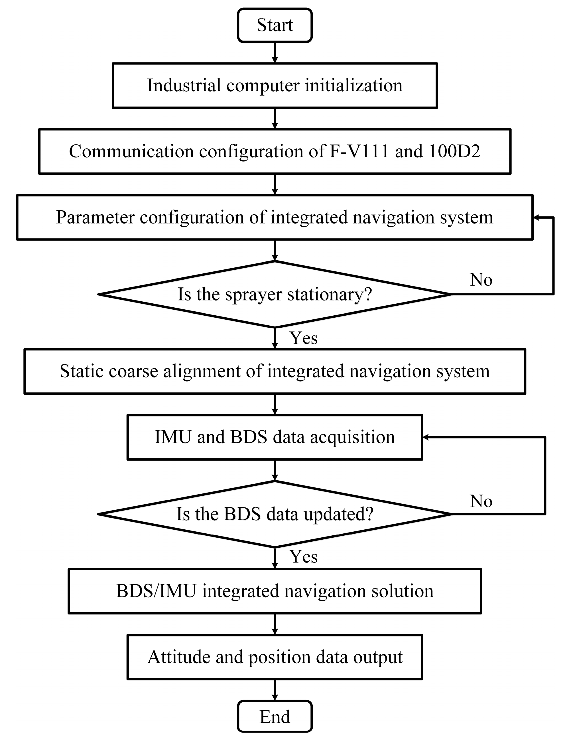
The integrated navigation program is shown in Figure 5. The on-board navigation system is powered on to initialise the industrial computer, F-V111 receiver, 100D2, etc. (1) The industrial computer checks the motherboard, graphics card and memory, and initializes peripherals such as the USB port; (2) The F-V111 receiver and 100D2 are configured; (3) The parameters of the integrated navigation system are configured, including the initial zero deviation and installation error angle of the 100D2, the bar arm between the F-V111 receiver antenna and 100D2, and the initial state vector X 0 , the initial error estimation covariance matrix P 0 , the initial system noise variance matrix Q 0 , the initial measurement noise variance matrix R 0 ; (4) The system enters polling and the performs static coarse alignment under the static state of the sprayer. The initial pitch angle and roll angle are calculated by the accelerometer of IMU, and the initial heading angle and longitude and latitude are calculated by F-V111 receiver; (5) The data of 100D2 is collected and the data of F-V111 receiver is waiting to be updated; (6) The longitude and latitude are obtained, and the integrated navigation solution is carried out to obtain the heading angle and position of spraying robot; (7) The system polls for the data of 100D2 and waits for the next data of F-V111 receiver update.

2.3. Control Model of the System

2.3.1. Navigation Control Principle of the Spraying Robot

The automatic navigation control system of the spraying robot was composed of the path tracking system. The structure of the path tracking system is shown in Figure 6. The path to be tracked is selected through the user interface and the automatic navigation start command is sent. The sprayer obtains the real-time information of position and heading, the path tracking algorithm searches the target point on the path and calculates the control parameters, sends the control parameters to the single chip microcomputer through the RS232 communication interface. The single chip microcomputer verifies the integrity of the control parameters, converts them into PWM signals to send to the servo motor driver, which controls the motor to drive the crawler moment. The path tracking algorithm keeps cycling until the distance between the actual position of the spraying robot and the last path point is less than 0.1 m or the automatic navigation termination command is sent out.

2.3.2. Kinematic Model of the Spraying Robot

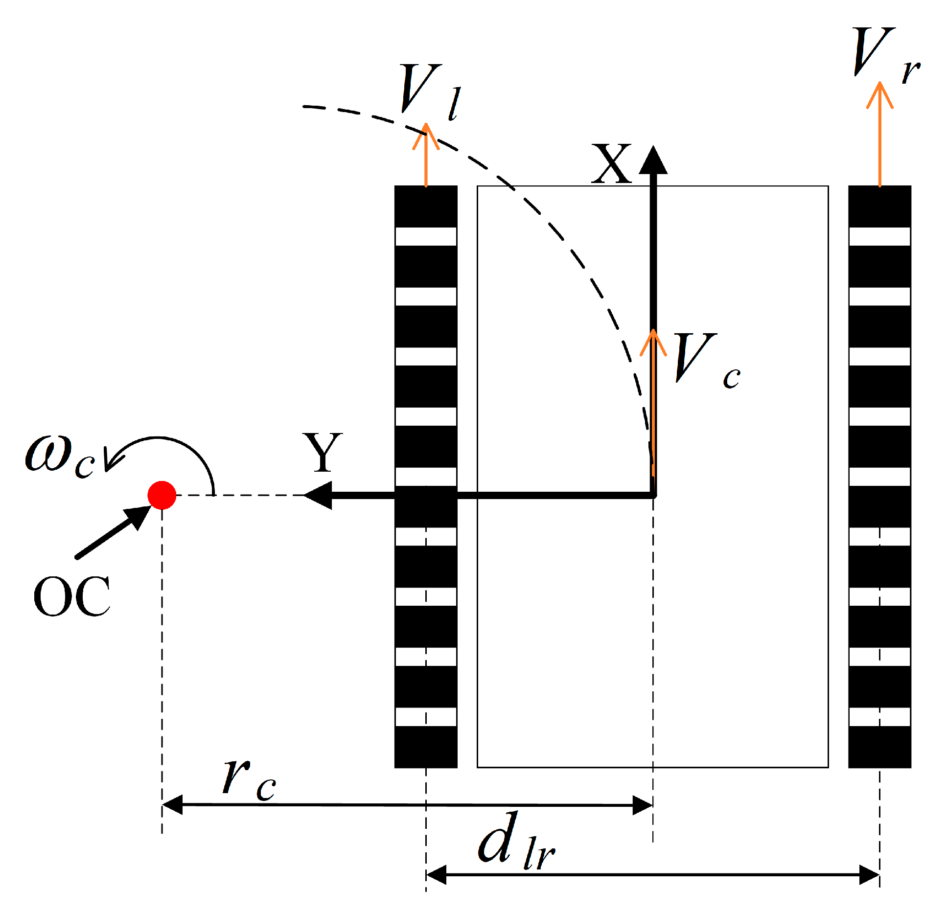
The chassis of the spraying robot adopts a track structure and adopts the principle of sliding steering to realize steering by controlling the relative speed of the tracks on both sides. Assuming that the spraying robot does not slip when driving, and the mass division of the robot is uniform, and the center of mass is located in the geometric longitudinal symmetry line of the robot, the coordinate system of the spraying robot is shown in Figure 7. According to the right-hand rule, the center of mass CM of spraying robot is the coordinate origin, the forward motion direction is the positive direction of the X-axis, the left is the positive direction of the Y-axis, the Z-axis is perpendicular to the paper facing outward, and OC is the center of rotation center of the sprayer, v c is the linear velocity of the center of mass, r c is the turning radius of the center of mass, v l , v r are the linear velocities of the left and right driving wheels, d l r is the distance between the two track centers, which is 0.62 m. The angular velocity ω of steering around the OC can be expressed as follows:
ω = v c r c = v r r c + d l r / 2 = v l r c d l r / 2
ω = ( v r v l ) / d l r
The linear velocity of the spraying robot centroid can be expressed as follows:
v c = ( v l + v r ) / 2
The turning radius of the spraying robot can be expressed as follows:
r c = ( v l + v r ) d l r 2 ( v r v l )
The forward kinematics model of the spraying robot can be expressed as follows:
[ v c ω ] = [ 1 / 2 1 / 2 1 / d l r 1 / d l r ] [ v r v l ]
The inverse kinematics model of the spraying robot can be expressed as follows:
[ v r v l ] = [ 1 d l r / 2 1 d l r / 2 ] [ v c ω ]

2.3.3. Pure Pursuit Model

The pure pursuit model is a method based on the geometric principle, in which the center of the rear axis of the spraying robot is the tangent point and the longitudinal direction of the body is the tangent line, and the spraying robot travels along the arc by controlling the steering angle. As shown in Figure 8, the spraying robot tracks the path AB, the current point C ( x c , y c ) and the forward-looking distance l d are known, and the point G ( x g , y g ) with the distance l d from the current position on the path is obtained. G is the next tracked point. R is the radius of the driving arc of the rear axle at a given steering angle, α is the angle between the body and the next tracked point. v c is the linear velocity at the center of the rear axle, ω c is the steering angular velocity around the OC.
R = l d 2 sin α
The steering angular velocity can be expressed as follows:
ω c = V c R = 2 V c sin α / l d
In each control cycle, the next point to be tracked is updated, the desired steering angle of the spraying robot in that control cycle is calculated and further the spraying robot path tracking is achieved by controlling the steering angular velocity ω c .

2.3.4. Path Planning

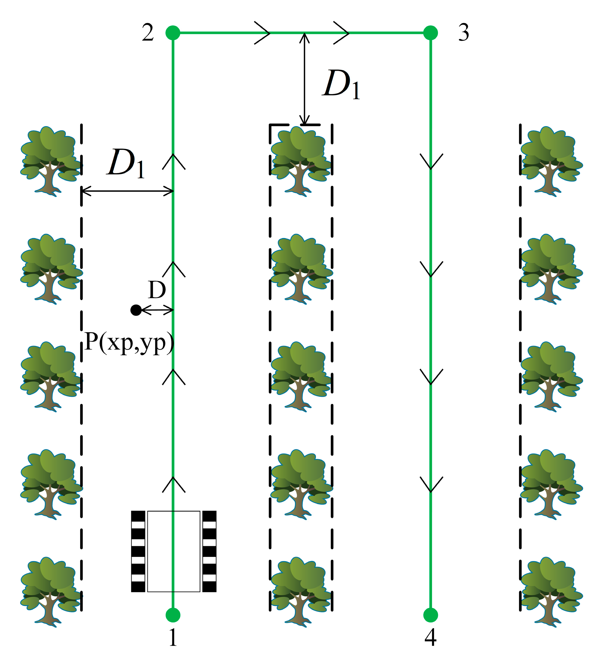
In view of the terrain characteristics and planting pattern of the orchard, the navigation path was designed as shown in Figure 9. The line with arrows represents the pre-set path, point 1 is the starting point, points 2 and 3 are the turning points, and point 4 is the stopping point. The point P is any point on the driving trajectory of the spraying robot operation, the vertical distance from the point P to the pre-navigation path is D, and D is used to evaluate the path tracking error. D 1 is the minimum safe distance for the spraying robot operation without touch the fruit trees. D is less than D 1 when the spraying robot operates, and D 1 > d l r / 2 .

3. Results

3.1. Static Positioning

In this experiment, the performance of the navigation system was tested under the static state of the spraying robot, and the results of BDS positioning alone and BDS/IMU combined positioning were compared. The test was conducted in the fruit tree Innovation Park of the Horticultural Research Institute of Hunan Academy of Agricultural Sciences, Changsha City, Hunan Province, China in March 2022. During the test, the spraying robot was static, and the system outputted the data of BDS positioning alone and BDS/IMU combined positioning at the same time. The deviation of position and heading angle from their corresponding mean values was used as error to measure the positioning and orientation accuracy. The heading angles and positions obtained from BDS and BDS/IMU integrated navigation system are shown in Figure 10. In BDS positioning, the position error was less than 1.5 cm, the mean values in X and Y direction were 0.413 and 0.574 cm, and the variances were 0.062 and 0.096, respectively. The heading angle error was less than 0.3°, the mean value was 129.409°, and the variance was 0.003223. In BDS/IMU integrated positioning, the position error was less than 1.5 cm, the mean values in the X and Y directions were 0.430 and 0.235 cm, and the variances were 0.060 and 0.087, respectively; The heading angle error was less than 0.25°, the mean value was 129.421°, and the variance was 0.002052.
It can be seen from Figure 10b that the signal variation in the last part of Figure 10d was caused by the variation in BDS measured heading angle. In the static state, the heading angle directly obtained by BDS itself has large random noise. At the same time, the disturbance of wind on the tree crown in the orchard block and interfere with the satellite signal to varying degrees, resulting in large fluctuations in BDS measured heading angle. Comparing Figure 10b,d, the heading angle measured by the untreated BDS fluctuates greatly. After integrating the BDS and IMU, the error caused by random drift is reduced and the accuracy of heading angle measurement is improved. The mean values of BDS/IMU integrated positioning and BDS positioning were closed, but the variance of integrated navigation was smaller, the positioning data of integrated navigation was relatively centralized, and the system was more stable. In terms of orientation, there is no obvious difference between the two. The BDS receiver with dual antennas can provide higher orientation accuracy under static conditions.

3.2. Dynamic Positioning

The performance of the navigation system was tested under the straight-line driving state of the spraying robot, and the BDS positioning and BDS/IMU integrated positioning were compared. In the test, the spraying robot ran along the preset straight line at a speed of 0.4 m/s, both BDS and BDS/IMU integrated positioning data were output. The heading angle and path data of the spraying robot for the BDS positioning and the BDS/IMU integrated positioning are shown in Figure 11. In BDS positioning, the position error was less than 5.29 cm, the mean errors in X and Y directions were 1.42 and 1.18 cm, and the variances were 1.95 and 1.35, respectively. The heading angle error was less than 3°, the mean value was 40.179°, and the variance was 0.5543. In BDS/IMU integrated positioning, the position error was less than 2.49 cm, the mean errors in X and Y directions were −0.37 and 0.31 cm, and the variances were 0.87 and 0.60, respectively. The heading angle error was less than 2°, the mean value was 40.430°, and the variance was 0.237.
It can be seen that in the moving state, the results of BDS/IMU integrated positioning are more accurate than that of BDS.

3.3. Auto-Navigation Performances in Orchard

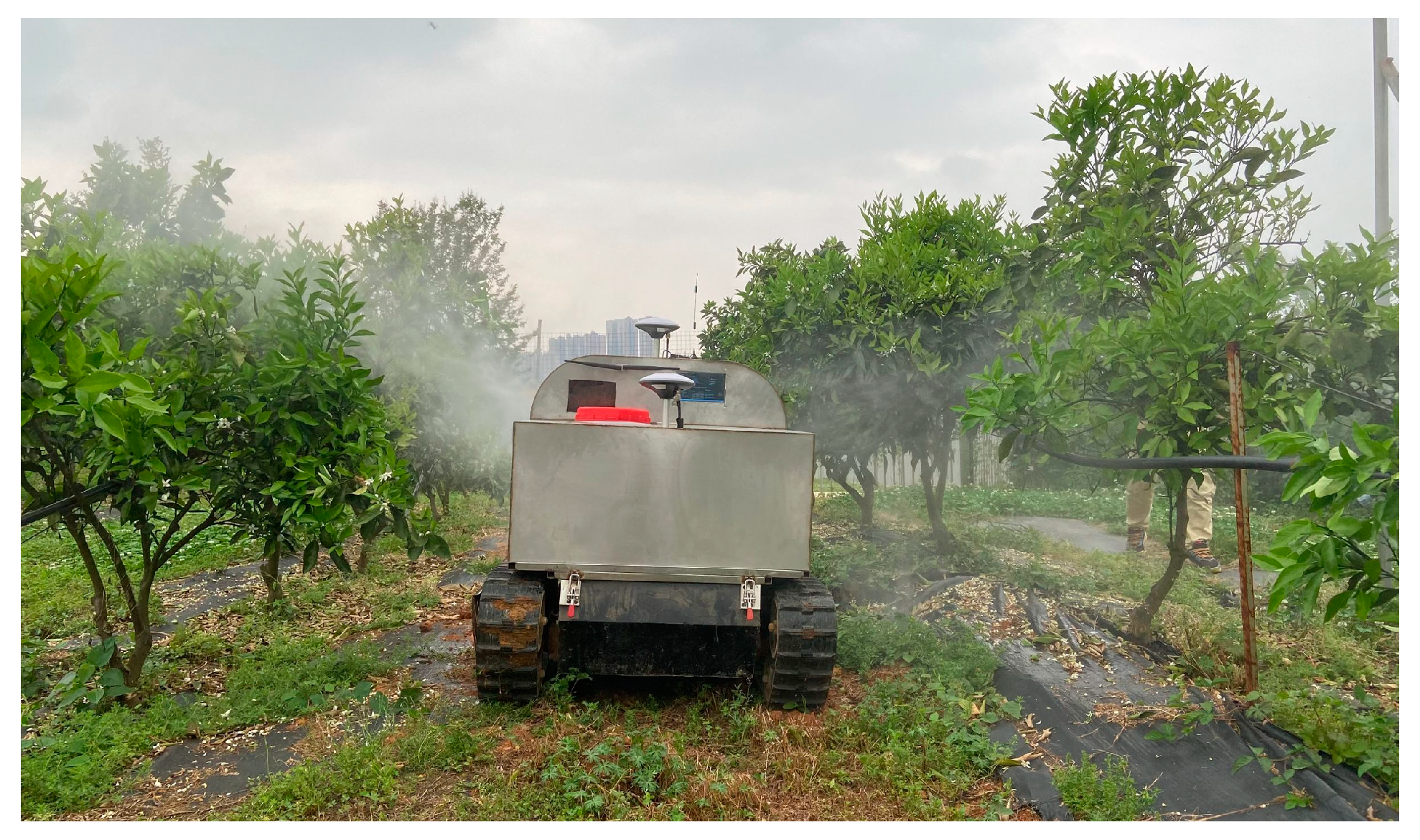
In order to verify the reliability and rationality of the automatic navigation system mounted on the sprayer, a linear navigation test was carried out in the orange orchard, as shown in Figure 12. The spacing of planting rows was 5 m, and the ridge length was about 35 m. Considering the outstretched part of the branches of orange trees, the actual width of the walkable area between ridges was 2 m, and the width of the body was 0.62 m. Therefore, the minimum safe distance was 0.69 m, which satisfied the path planning requirements. Two continuous ridges of orange orchards were randomly selected as the test site. Before the test, the high-precision positioning board was used to collect the coordinates of points 1–4 on the planned path, the path planning scheme shown in Figure 9 was employed for the orchard path tracking test and the automatic navigation driving speed of the sprayer was 0.4 m/s. The experiment was conducted at the fruit tree Innovation Park of the Horticultural Research Institute of Hunan Academy of Agricultural Sciences, Changsha City, Hunan Province on 7 April 2022.
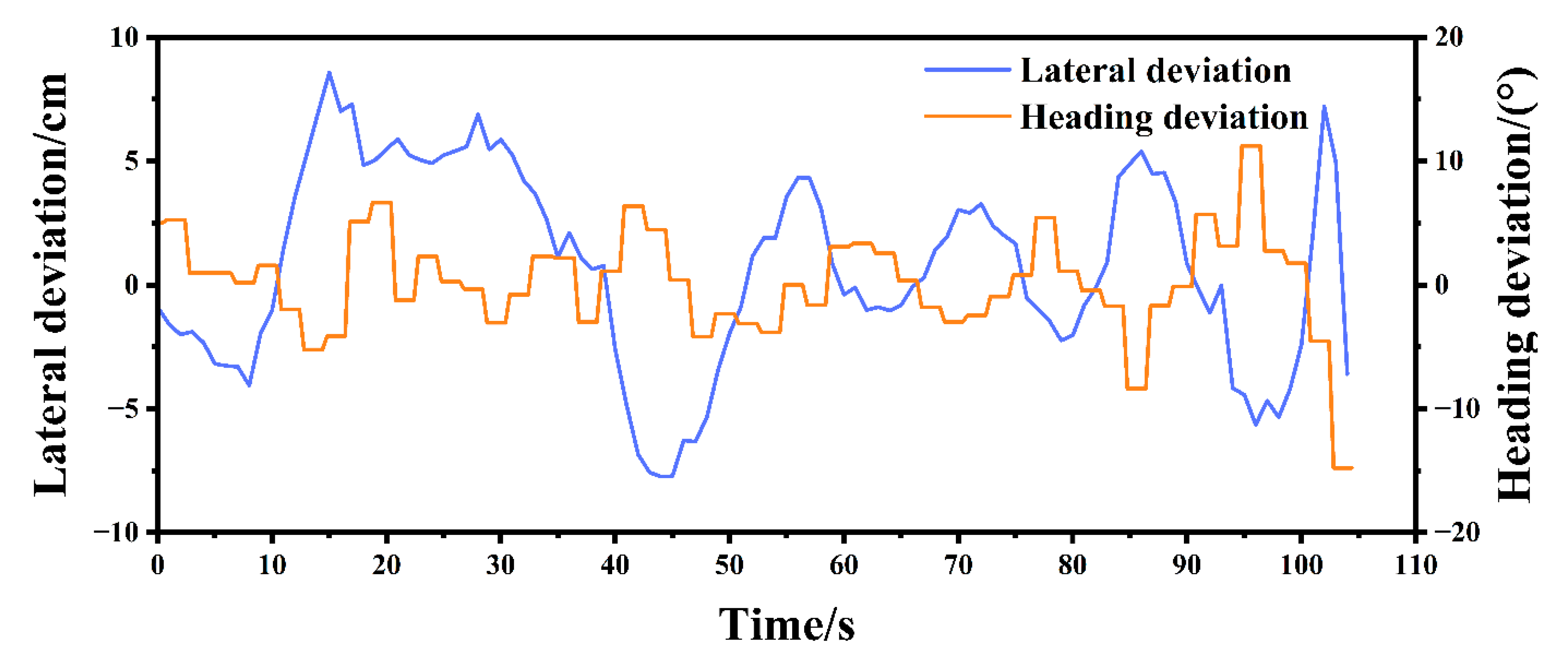
When the sprayer was spraying in the orange orchard, the straight-line navigation automatic driving experiments were carried out five times. The maximum lateral tracking error was as low as 8.58 cm, if the path tracking algorithm is stable. However, the maximum lateral tracking error of the spraying robot was 10.77 cm due to the orchard field soil environment, such as side slip resulting from field ridge and steep hill. However, the tracking accuracy is acceptable because of its large operation width. We can conclude that the orchard soil condition and ground-surface undulation, especially for heavier spraying robots when the medicine box is filled with pesticides. Since the heading is only employed to correct the positioning error, the lever-arm error coming from pitch and roll is not compensated. The navigation deviation information on the fourth route was shown in Figure 13. The results of the five groups of experiments were summarized in Table 1. Through calculation, the error of the average absolute value was 3.55 cm, and the overall root mean square error of the lateral deviation absolute value was 1.19 cm. The field tests showed that the maximum offset error was no more than 10.77 cm. Take a certain navigation line to perform linear trajectory fitting, and the navigation effect is shown in Figure 14.

4. Discussion and Conclusions

To address the unstableness of the satellite navigation system, which is caused by blocking, signal loss, and random error, an integrated navigation algorithm was built using the error Kalman filter that is based on measurements of position and heading angle to enhance the performance of the navigation system for long-term operation. The BDS and BDS/IMU integrated navigation system positioning tests were carried out in the closed orchard. The static experiments showed that the positioning error of the BDS was within 1.5 cm, the heading angle error was within 0.3°, and the variance was 0.003223. The positioning error of BDS/IMU integrated navigation system was within 1.5 cm, the heading angle error was within 0.25°, and the variance was 0.002052. The results indicated that the positioning and heading angle measurement performance of the BDS/IMU integrated navigation system was slightly better than that of BDS, which had more centralized data and better stability. The dynamic straight-line driving positioning experiments showed that the positioning error of BDS was within 5.29 cm, the heading angle error was within 3°, and the variance was 0.5543. The positioning error of BDS/IMU integrated navigation system was within 2.49 cm, the heading angle error was within 2°, and the variance was 0.237. These results implied that the performance of positioning and heading angle measurements of BDS/IMU integrated navigation system was significantly higher than that of BDS, and better than the integrated navigation system using Kalman filter with non-error observation. The kinematic model and pure tracking model of the pesticide robot were established, and the path tracking control algorithm of the sprayer robot was designed. The path planning was carried out in combination with the orchard terrain, and the navigation test was conducted in the closed orchard. The test results showed that when the operating speed of the sprayer robot was 0.4 m/s, the maximum error of linear tracking was less than 10.77 cm, and the average absolute error was 3.55 cm, which was superior to the tractor automatic navigation system based on DGPS (the maximum error of straight-line tracking is less than 15 cm) and the orchard sprayer automatic navigation system based on BDS (the maximum error of straight-line tracking is less than 13 cm). The field tests indicated that the auto-navigation system was appropriated to orchard spraying robots.
In the future, the BDS/IMU integrated navigation systems should be enhanced by integrating lidar and image sensors, which not only provide higher precision position and attitude data but also ensure the navigation functionalities, such as automatic obstacle avoidance and automatic in and out of warehouses, in orchards and agricultural machinery warehouses, when the tree crown or roof completely blocks the satellite signal. In addition, although the integrated navigation method based on Kalman filter can fuse the sensor information at different rates through the data synchronization processing method and calculate the navigation solution in real time, in order to maintain the data synchronization, it is often necessary to discard some measured values, resulting in a waste of information. At the same time, the standard Kalman filter can only solve the linear problem, while most sensor models contain nonlinear components, the estimated value is not optimal, and does not support the expansion of new navigation sensors. Therefore, the nonlinear optimization method is further studied to realize the fusion of multi-sensor asynchronous measurement data, and the plug and play function can be realized according to the availability of sensors; however, there are problems remaining to be further investigated, such as the unconstrained vibrations of the spraying robot, and large horizontal deviation when it is at the corner. To reduce the horizontal deviation and vibration of the automatic navigation system, new control strategies, such as coupling with neural networks, should be implemented in the future to eliminate the impact of sideslip and row change on path tracking during spraying.

Author Contributions

Conceptualization, M.L., K.F. and L.Z.; methodology, L.Z.; software, L.Z.; formal analysis, L.Z.; data curation, J.H. (Jingjing Huang); investigation, J.H. (Jinqi Huang), J.X., X.X., X.W. and G.Y.; writing—original draft, L.Z.; writing—review and editing, L.Z., J.H. (Jingjing Huang), X.Z., M.L. and K.F.; supervision, X.Z., M.L. and K.F.; project administration, X.Z., M.L. and K.F.; funding acquisition, X.Z., M.L. and K.F. All authors have read and agreed to the published version of the manuscript.

Funding

This work was sponsored by the National Science Foundation of Hunan Province (2021JJ40287), the research and development of key projects in Hunan Province (2017NK2380), the National Science Foundation of Changsha City (kq2014174).

Institutional Review Board Statement

Not applicable.

Informed Consent Statement

Not applicable.

Data Availability Statement

Not applicable.

Acknowledgments

We wish to thank the support of the above foundations.

Conflicts of Interest

The authors declare no conflict of interest.

References

  1. Zhao, Y.; Xiao, H.; Mei, S.; Song, Z.; Ding, W.; Jing, Y. Current status and development strategies of orchard mechanization production in China. J. China Agric. Univ. 2017, 22, 116–127. [Google Scholar]
  2. Zheng, Y.; Chen, B.; Lyu, H.; Kang, F.; Jiang, S. Research progress of orchard plant protection mechanization technology and equipment in China. Trans. Chin. Soc. Agric. Eng. 2020, 36, 110–124. [Google Scholar]
  3. Shamshiri, R.R.; Weltzien, C.; Hameed, I.A.; Yule, I.J.; Grift, T.E.; Balasundram, S.K.; Pitonakova, L.; Ahmad, D.; Chowdhary, G. Research and development in agricultural robotics: A perspective of digital farming. Int. J. Agric. Biol. Eng. 2018, 11, 1–14. [Google Scholar] [CrossRef]
  4. Malavazi, F.B.; Guyonneau, R.; Fasquel, J.-B.; Lagrange, S.; Mercier, F. LiDAR-only based navigation algorithm for an autonomous agricultural robot. Comput. Electron. Agric. 2018, 154, 71–79. [Google Scholar] [CrossRef]
  5. Yang, Q.; Qu, D.; Xu, F.; Zou, F.; He, G.; Sun, M. Mobile robot motion control and autonomous navigation in GPS-denied outdoor environments using 3D laser scanning. Assem. Autom. 2018, 15439, 469–478. [Google Scholar] [CrossRef]
  6. Jones, M.H.; Bell, J.; Dredge, D.; Seabright, M.; Scarfe, A.; Duke, M.; MacDonald, B. Design and testing of a heavy-duty platform for autonomous navigation in kiwifruit orchards. Biosyst. Eng. 2019, 187, 129–146. [Google Scholar] [CrossRef]
  7. Opiyo, S.; Okinda, C.; Zhou, J.; Mwangi, E.; Makange, N. Medial axis-based machine-vision system for orchard robot navigation. Comput. Electron. Agric. 2021, 185, 106153. [Google Scholar] [CrossRef]
  8. Ponnambalam, V.R.; Bakken, M.; Moore, R.J.; Glenn Omholt Gjevestad, J.; Johan From, P. Autonomous crop row guidance using adaptive multi-roi in strawberry fields. Sensors 2020, 20, 5249. [Google Scholar] [CrossRef] [PubMed]
  9. Ma, Y.; Zhang, W.; Qureshi, W.S.; Gao, C.; Zhang, C.; Li, W. Autonomous navigation for a wolfberry picking robot using visual cues and fuzzy control. Inf. Process. Agric. 2021, 8, 15–26. [Google Scholar] [CrossRef]
  10. Li, Y.; Hu, Z.; Hu, Y.; Chu, D. Integration of vision and topological self-localization for intelligent vehicles. Mechatronics 2018, 51, 46–58. [Google Scholar] [CrossRef]
  11. Tu, X.; Gai, J.; Tang, L. Robust navigation control of a 4WD/4WS agricultural robotic vehicle. Comput. Electron. Agric. 2019, 164, 104892. [Google Scholar] [CrossRef]
  12. Yin, X.; Wang, Y.; Chen, Y.; Jin, C.; Du, J. Development of autonomous navigation controller for agricultural vehicles. Int. J. Agric. Biol. Eng. 2020, 13, 70–76. [Google Scholar] [CrossRef]
  13. Barawid, O.C., Jr.; Mizushima, A.; Ishii, K.; Noguchi, N. Development of an autonomous navigation system using a two-dimensional laser scanner in an orchard application. Biosyst. Eng. 2007, 96, 139–149. [Google Scholar] [CrossRef]
  14. Thanpattranon, P.; Ahamed, T.; Takigawa, T. Navigation of autonomous tractor for orchards and plantations using a laser range finder: Automatic control of trailer position with tractor. Biosyst. Eng. 2016, 147, 90–103. [Google Scholar] [CrossRef]
  15. Ai, C.; Lin, H.; Wu, D.; Feng, Z. Path planning algorithm for plant protection robots in vineyard. Trans. Chin. Soc. Agric. Eng. 2018, 34, 77–85. [Google Scholar]
  16. Guo, C.; Fan, Y.; Zhang, S.; Chen, J. Progress on vehicle automatic navigation in orchard. J. Northeast. Agric. Univ. 2019, 50, 87–96. [Google Scholar]
  17. Han, Z.; Li, J.; Yuan, Y.; Fang, X.; Zhao, B.; Zhu, L. Path Recognition of Orchard Visual Navigation Based on U-Net. Trans. Chin. Soc. Agric. Mach. 2021, 52, 30–39. [Google Scholar]
  18. Li, W. Research on the Method of Generating Visual Navigation Path of Kiwi Picking Robot. Master’s Thesis, Northwest A&F University, Xianyang, China, 1 May 2017. [Google Scholar]
  19. Wang, Y.; Liu, B.; Xiong, L.; Wang, Z.; Yang, C. Research on generating algorithm of orchard road navigation line based on deep learning. J. Hunan Agric. Univ. 2019, 45, 674–678. [Google Scholar]
  20. Ma, C.; Dong, Z.; Chen, Z.; Zhu, Y.; Shi, F. Research on navigation line generation of kiwi orchard between rows based on root point substitution. Agric. Res. Arid. Areas 2021, 39, 222–230. [Google Scholar]
  21. Radcliffe, J.; Cox, J.; Bulanon, D.M. Machine vision for orchard navigation. Comput. Ind. 2018, 98, 165–171. [Google Scholar] [CrossRef]
  22. Luo, X.; Zhang, Z.; Zhao, Z.; Chen, B.; Hu, L.; Wu, X. Design of DGPS navigation control system for Dongfanghong X-804 tractor. Trans. CSAE 2009, 25, 139–145. [Google Scholar]
  23. Nagasaka, Y.; Umeda, N.; Kanetai, Y.; Taniwaki, K.; Sasaki, Y. Autonomous guidance for rice transplanting using global positioning and gyroscopes. Comput. Electron. Agric. 2004, 43, 223–234. [Google Scholar] [CrossRef]
  24. Xiong, B.; Zhang, J.; Qu, F.; Fan, Z.; Wang, D.; Li, W. Navigation Control System for Orchard Spraying Machine Based on Beidou Navigation Satellite System. Trans. Chin. Soc. Agric. Mach. 2017, 48, 45–50. [Google Scholar]
  25. Zhang, S.; Guo, C.; Gao, Z.; Sugirbay, A.; Chen, J.; Chen, Y. Research on 2D Laser Automatic Navigation Control for Standardized Orchard. Appl. Sci. 2020, 10, 2763. [Google Scholar] [CrossRef]
  26. Chen, J.Q.; Qiang, H.; Wu, J.; Xu, G.; Wang, Z.; Liu, X. Extracting the navigation path of a tomato-cucumber greenhouse robot based on a median point Hough transform. Comput. Electron. Agric. 2020, 174, 105472. [Google Scholar] [CrossRef]
  27. Inoue, K.; Kaizu, Y.; Igarashi, S.; Imou, K. The development of autonomous navigation and obstacle avoidance for a robotic mower using machine vision technique. IFAC-PapersOnLine 2019, 52, 173–177. [Google Scholar] [CrossRef]
  28. Zuo, Z.; Wang, Y.; Chen, P.; Wu, Y. Application of a Gaussian processes based central difference Kalman filter in the BDS/IMS integrated system. J. Chin. Inert. Technol. 2020, 28, 192–198. [Google Scholar]
  29. Gao, W.; Zhang, Y.; Wang, J. A strapdown interial navigation system/beidou/doppler velocity log integrated navigation algorithm based on a cubature kalman filter. Sensors 2014, 14, 1511–1527. [Google Scholar] [CrossRef]
  30. Zhang, J.; Wen, W.; Huang, F.; Wang, Y.; Chen, X.; Hsu, L.-T. GNSS-RTK Adaptively Integrated with LiDAR/IMU Odometry for Continuously Global Positioning in Urban Canyons. Appl. Sci. 2022, 12, 5193. [Google Scholar] [CrossRef]
  31. Karaim, M.; Tamazin, M.; Noureldin, A. An Efficient Ultra-Tight GPS/RISS Integrated System for Challenging Navigation Environments. Appl. Sci. 2020, 10, 3613. [Google Scholar] [CrossRef]
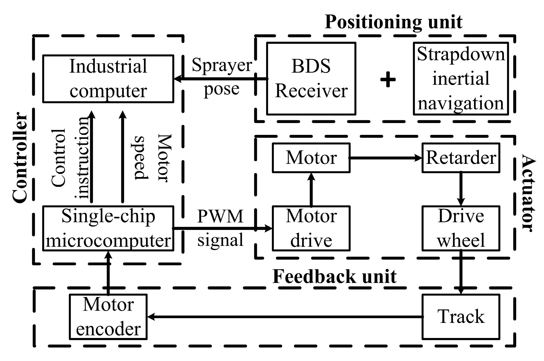
Figure 1. The design of the automatic navigation system of the spraying robot.
Applsci 12 08173 g001
Figure 2. Physical construction of the orchard spraying robot. Note: 1 is sprinkler; 2 is medicine tank; 3 is BDS receiver antenna; 4 is track; 5 is upper guide wheel; 6 is lower guide wheel; 7 is trust wheel; 8 is suspension tension spring; 9 is suspension; 10 is supporting wheel. 11 is driving wheel.
Applsci 12 08173 g002
Figure 3. The IMU solution process. Note: L is latitude, λ is longitude, (°); h is altitude, m; Φ, θ , γ is pitch angle, heading angle and roll angle, rad; C b n ( 0 ) is the attitude matrix of spraying robot at initial stage; f i b b is the specific force projection of the coordinate system b (sprayer coordinate system) with reference to the coordinate system i (geocentric inertial coordinate system) under the coordinate system b , m · s 2 ; V e b n is the velocity projection of the coordinate system b with reference to the coordinate system e (earth centered earth fixed) under the coordinate system n (east-north-sky navigation coordinate system), m · s 1 ; C is the directional cosine matrix, ω is the angular velocity, rad · s 1 , the upper comer indicates the coordinate system of the variable, the lower comer indicates the transformation coordinate system.
Applsci 12 08173 g003
Figure 4. Flow chart of BDS/IMU integrated navigation based on error Kalman filter.
Applsci 12 08173 g004
Figure 5. The flow chart of the integrated navigation program.
Applsci 12 08173 g005
Figure 6. The structure of the path tracking system.
Applsci 12 08173 g006
Figure 7. The kinematic model of the spraying robot.
Applsci 12 08173 g007
Figure 8. The pure pursuit model of the spraying robot.
Applsci 12 08173 g008
Figure 9. The path planning for the spraying robot in the citrus orchard.
Applsci 12 08173 g009
Figure 10. The positioning results of the spraying robot in the static experiments. (a) Positioning measurements of BDS in static state; (b) Heading angle measurements of BDS in static state; (c) Positioning measurements of BDS/IMU in static state; (d) Heading angle measurements of BDS/IMU in static state.
Applsci 12 08173 g010
Figure 11. The positioning results of the spraying robot in the straight-line running experiments. (a) Positioning measurements using BDS; (b) Heading angle measurements using BDS; (c) Positioning measurements using BDS/IMU integrated system; (d) Heading angle measurements using BDS/IMU integrated system.
Applsci 12 08173 g011
Figure 12. Field test of the spraying robot navigation system.
Applsci 12 08173 g012
Figure 13. The diagram of the lateral and heading deviation.
Applsci 12 08173 g013
Figure 14. The navigation trajectory of the spraying robot.
Applsci 12 08173 g014
Table 1. The results of the navigation experiments in the citrus orchard.
Line NumberTime/sMaximum Error/cmMinimum Error/cmAverage Absolute Error/cmRoot Mean Square Error/cm
1109.008.580.013.231.21
2108.019.360.062.960.35
3108.0110.770.063.931.73
4108.019.980.114.162.37
5110.009.320.013.480.29
Overall///3.551.19
Publisher’s Note: MDPI stays neutral with regard to jurisdictional claims in published maps and institutional affiliations.