Abstract
To improve the poor characteristics of low strength and high compressibility of weak silty soil, a series of samples with different cement dosage, fiber content, and fiber length was prepared in this experiment, and unconfined compressive strength (UCS) tests, triaxial tests, and scanning electron microscopy (SEM) tests were carried out to explore the influence of polypropylene fiber on the strength of cement-stabilized soil and analyze the curing mechanism of fiber-reinforced cement soil. The test results show that the factors affecting the UCS of the sample from high to low were: cement dosage, fiber content, and fiber length. An orthogonal test found that the optimal ratio of the sample was cement dosage of 18%, fiber content of 0.4%, and fiber length of 3 mm, and the UCS of the sample can reach 1.63 MPa. The triaxial test shows that when the cement dosage is 15% and the fiber length is 9 mm, the incorporation of fiber can significantly improve the toughness and strength of soil. When the cement dosage is 15%, the UCS with 0.4% fiber content is 1.6 times that without fiber. With the increase of fiber content, the peak stress and axial strain of fiber-cured soil are increased, and the cohesion and internal friction angle are also increased. The failure mode and SEM test of fiber-reinforced cement soil show that when the cement dosage is 15% and the fiber length is 9 mm, the addition of fiber can improve the deformation ability of cement soil and slow down the development of cracks. With the increase in fiber content, the number and width of cracks are significantly reduced, and the failure mode changes from brittle failure to ductile failure.
1. Introduction
Soil with low strength and high compressibility easily causes uneven settlement of a foundation, resulting in cracking and collapse of buildings, which seriously threatens people’s lives and health and property safety [1,2,3]. Based on this situation, domestic and foreign scholars have proposed chemical reinforcement and physical reinforcement methods to solve the problem of such soil reinforcement [4,5,6]. Chemical reinforcement improves the strength of the soil through the addition of chemical materials to the soil for mixing to make it react with the soil particles to generate new substances. The commonly used chemical reinforcement materials mainly included cement [7,8], lime [9], and fly ash [10,11,12,13]. Although chemical reinforcement can significantly improve the compressive strength of soil, it was difficult to improve the tensile and flexural properties of soil [4]. Physical reinforcement technology not only improves the strength of soil but also greatly improves the physical and mechanical properties of soil, such as tensile and flexural strength, so it has been widely used. The commonly used soil reinforcement materials include cotton and hemp products [9,14,15,16], geotextile [17,18,19], polypropylene fiber [20,21,22,23,24,25,26], glass fiber [27], basalt fiber [27,28,29], and steel fiber [7,25]. The natural tensile properties, surface friction properties, and good dispersion of these materials make them connected with the cementitious substances produced by the hydration reaction of cement in a network structure, which enhances the bonding force of the contact interface and improves the ability of soil to resist deformation.
Studies have shown that fiber, as a commonly used soil reinforcement material, has been widely used in new curing agents combined with fiber-modified silt solidified soil, fiber-modified microbial solidified marine sand, fiber-reinforced cement solidified dredged soil, fiber-modified geopolymer solidified soil shrinkage/cracking and fiber application in concrete. Chen Ruimin et al. [30] improved silt solidified soil by using cement-slag-fly ash-gypsum curing agent and polypropylene fiber and found that the failure mode was improved, changing from brittle mode to ductile mode. The optimum fiber content and fiber length were 0.4% and 12 mm, respectively. Wang Han et al. [31] used microbial-induced calcium carbonate precipitation technology combined with activated carbon to solidify marine sand, and brittle failure occurred when it was damaged. The incorporation of sisal fiber could improve this situation, and the optimal content of fiber was 0.2% with or without activated carbon. To improve the brittle fracture behavior of sand, Ma Ke et al. [32] used a polyurethane curing agent and sisal fiber. The addition of fiber can improve not only the tensile and compressive properties of sand but also the residual strength of sand. Wang Zhenglong et al. [33] solidified dredged soil with high moisture content, low permeability, and low bearing capacity by using ordinary Portland cement and polyvinyl alcohol fiber. With the increase in curing age, the influence of fiber on internal friction angle decreased gradually, and the optimal fiber content and length were 0.1% and 6 mm, respectively. Wang Yi et al. [34] artificially improved the cracking problem of geopolymer-solidified soil and found that the fiber had a good anti-cracking effect in the continuous drying test and dry-wet cycle test by using ash-based polymer and coconut fiber-solidified soil. Hao Jianbin et al. [35] explored the improvement effect of sisal fiber and conducted experiments on plain expansive soil, fly ash-modified soil, and fly ash combined with sisal fiber composite modified soil. They found that the addition of fly ash and fiber could improve the strength of soil, and the effect of composite modified soil was better. The optimal ratio of fly ash and fiber content was 9% and 0.4%, respectively, and the fiber length was 20 mm. J Siswanto et al. [36] improved the compressive and tensile strength of soil by adding bamboo fiber. Jiang Ping et al. [37] studied lime and fly ash synergistic polypropylene fiber-reinforced expandable poly-styrene lightweight soil. The California bearing ratio (CBR) value decreased with the increase in the lightweight soil particle content in the bearing ratio test, and the addition of fiber can improve the CBR value, with the best effect being achieved when the fiber content is 0.1%. Li Yuelin et al. [38] used calcined cement solid waste chopped soil stirring residue instead of cement and mixed with polyvinyl alcohol fiber. The addition of fiber significantly improved the tensile strain capacity, and the maximum value was 3.2%. Shen Yuanshun et al. [39] used polyester fiber to improve lime or cement solidified soil and found that lime and cement could improve the compressive strength of soil, and the addition of fiber could improve the failure mode of soil and play a role in resisting deformation. Yu Xiao et al. [40] studied the reinforcement effect of rice husk and polypropylene fiber on the mechanical properties in three types of cement-stabilized soils (clayey sand (SC), sandy clay of low liquid limit (CLS), and low liquid limit clay (CL)). The experimental results reveal that the addition of rice husks and polypropylene fibers in cement-stabilized soil significantly improved the unconfined compressive strength (UCS) and split tensile strength (STS). Longyu Lu et al. [41] studied the mechanical and hydraulic behavior of four different cement-soil composites under confining pressure of 100–900 kPa by consolidated undrained triaxial shear test and permeability test. It was found that the combination of fly ash and sisal fiber greatly improved the peak strength of cemented soil, and the addition of sisal fiber reduced the permeability. Jihao Gong et al. [42] found that fibers are essential in reinforcing the mechanical properties of ultra-high performance concrete (UHPC), particularly the tensile and flexural strength.
As a typical fiber material, polypropylene fiber has been widely used in soil reinforcement due to its light weight, good dispersion, high elastic modulus, and high tensile strength. Studies have shown that polypropylene fiber cement soil combines the advantages of chemical reinforcement and physical reinforcement, which can not only improve the compressive strength of soil but also improve the shear resistance and deformation ability of soil [43]. Domestic and foreign scholars have conducted extensive research on fiber-solidified soil based on uniaxial and triaxial tests, analyzed the curing mechanism of polypropylene fiber to improve the shear strength of soil [26,44,45], and explored the curve-fitting state of fiber cement soil under compression [11,17,46]. For example, Tang Chaosheng et al. [20] tested fiber-reinforced cement soil and non-cement soil and found that the addition of discrete fibers can improve the shear strength of a cement-solidified body. Cheng Qiangqiang et al. [12] studied marine clay by conducting an unconfined compressive strength test. The addition of fiber improves the compressive strength of cement soil and the axial strain corresponding to the peak stress. The failure mode of cement soil without fiber is brittle failure, while the failure mode of cement soil with fiber is plastic failure. Fatahi, B et al. [7], through different fiber types, including polypropylene, carpet, steel fiber and other solidified cement soil, found in the unconfined compressive strength test that the addition of fiber improved the shear strength of soil, transforming brittle failure into ductile failure, and the compressive strength increased with the increase in the fiber con-tent. The tensile test proved that the addition of fiber improved the tensile strength of soil. P Jamsawang et al. [24] studied the effect of polypropylene fiber on the flexural strength of cement-reinforced sand and found that polypropylene fiber can improve the flexural response and failure mode of cement-reinforced sand. Liu JianLong et al. [14] analyzed the interaction mode between fiber and soil particles by conducting a triaxial shear test. The test showed that the contact, bending, and weaving between soil particles and fiber provided interface shear stress for soil particles and fiber.
In summary, at present, the solidification means of silt soil mainly include chemical solidification, which has the disadvantage of poor tensile and flexural properties of cement soil. The cement and polypropylene fiber improvement technology has the advantages of high strength and strong resistance to deformation and has achieved a good curing effect in the improvement of sandy soil, marine clay, light soil, concrete, and other soil. However, the strength of fiber-reinforced cement solidified sludge is affected by the cement content, fiber content, and fiber length. The current research mainly focuses on 1–2 factors, with a single focus. Therefore, this paper takes Nansha silt of Guangzhou as the research object, ordinary Portland cement as the curing agent, and polypropylene fiber as the reinforcing material, and prepares fiber-reinforced cement soil samples with different cement dosages and different fiber content and length. A series of unconfined compressive strength tests and triaxial shear tests are carried out, and the effects of fiber content, fiber length, and cement content on the shear strength of fiber-reinforced cement soil are analyzed, The microcosmic control mechanism of ordinary Portland cement and polypropylene fiber to solidify silt is explored, and the constitutive equation of fiber reinforced cement soil is derived. The expected results can provide a reference for geotechnical engineering factors such as foundation treatment, filling slope, and foundation pit support.
2. Sample Preparation and Test Scheme of Unconfined Compressive Strength
2.1. Preparation of Test Samples
The silty clay used in the test was taken from Nansha Terminal in Guangzhou, with a depth of 5 m below the surface. The moisture content of the soil sample was 60%, the void ratio was 1.64, and the liquid limit and plastic limit were 46.2% and 26.4%, respectively. The physical and mechanical parameters of silt were measured by the standard of the geotechnical test method (GB/T 50123-2019). The physical and mechanical parameters are shown in Table 1. The cement used in the test was 42.5 ordinary Portland cement of the Shijin brand in Guangzhou. The main components were calcium oxide, silicon dioxide, and aluminum oxide. The fibers used in the experiment were polypropylene fibers with bundled monofilaments, the specific parameters were given by the merchants. As shown in Figure 1 and Table 2. It was a polymer compound formed by polymers and has high tensile strength, light weight, high acid-base resistance, and good dispersion.

Table 1.
Physical and mechanical properties of silty soil in Nansha District, Guangzhou.
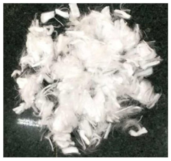
Figure 1.
Polypropylene fiber.
Table 2.
Physical and mechanical parameters of polypropylene fiber.
The preparation methods of test samples were as follows: (1) The undisturbed soil was dried between 105 °C and 110 °C for 24 h, and then placed in a crusher for crushing, with the soil sample requiring a 2 mm sieve; (2) The screened soil sample was fully mixed with monofilament polypropylene fiber by using the dry mixing method, and then an appropriate amount of water was added to ensure that the moisture content was 60%, and it was kept for 1 d after sealing; (3) Cement with different ratios was added to the infiltrated fiber soil and placed in the mortar mixer for uniform mixing; (4) The cylindrical mold with a diameter of 39.1 mm and a height of 80 mm was adopted, and Vaseline was uniformly smeared on the inner wall of the cylindrical mold. The mixed uniform fiber cement soil was placed in the mold in three layers, and the bubbles were eliminated by vibrating the vibration table. After one day of curing, the sample was removed from the mold and placed in the curing box. The curing temperature was controlled at (25 ± 2) °C, and the relative humidity was not less than 95%. The sample of fiber cement soil is shown in Figure 2. The test samples were suitable for the UCS test, triaxial test, and scanning electron microscopy (SEM) test.
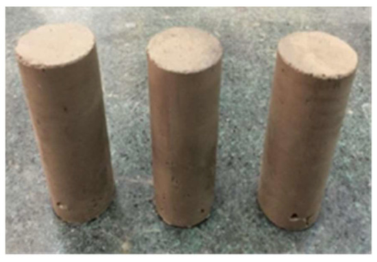
Figure 2.
Sample diagram of fiber cement soil.
2.2. Test Method
The UCS test used YAW-S300 liquid crystal automatic pressure testing machine. The sample was placed in the middle of the contact plate of the instrument, and the loading rate of the instrument was adjusted to 1.0 mm/min. The ultimate load of the sample was recorded when the sample was destroyed. The numerical value was converted to UCS. The average value of three parallel samples was taken as the final UCS of the sample, and the camera was used to record the sample after failure. The test instrument was shown in Figure 3.
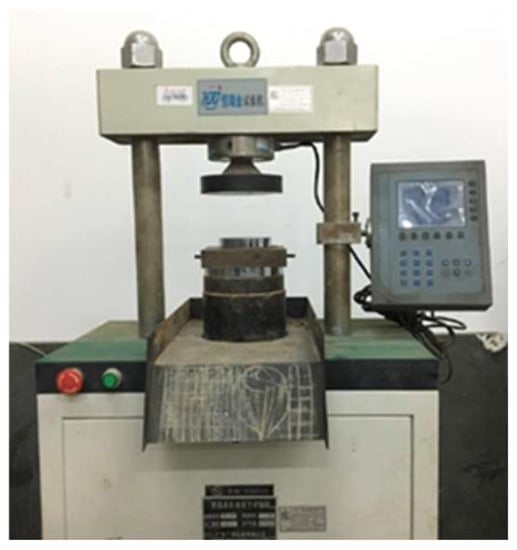
Figure 3.
Liquid crystal automatic pressure testing machine.
Unconsolidated undrained (UU) test adopted TSZ10-1.0 strain-controlled triaxial apparatus (precision was 0.005 KN). Referring to the standard of the geotechnical test method (GB/T 50123-2019), the concrete implementation was as follows: the sample was installed with rubber mold, and the sample was fixed on the instrument by triaxial mold. According to the UU test requirements, the drainage valve was always closed during the application of confining pressure σ3 and vertical stress σ1–σ3. When the confining pressure σ3 and vertical stress σ1–σ3 were applied, the sample begins to deform, and the pressure increment and the deformation of the sample were read out, respectively. When the axial strain of the sample reaches 15%, the test ends. The shear rate used in this test s 0.5 mm/min, and the confining pressure was 100 kPa, 200 kPa, and 400 kPa. The test instrument is shown in Figure 4.
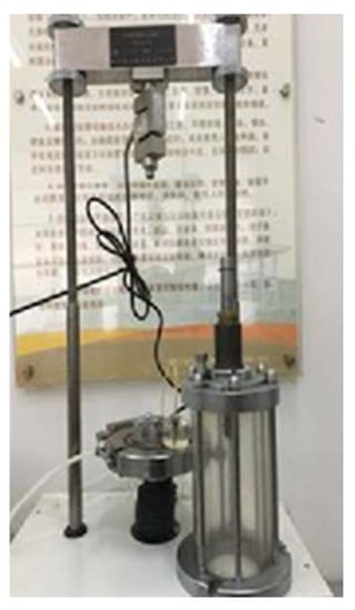
Figure 4.
Strain-controlled triaxial apparatus.
The FEI Quanta SEM was used in the SEM test. The part of the sample that had completed the unconfined compressive strength test was put into the oven for 24 h of low temperature (60 ± 3 °C) air drying treatment. The dry sample was taken out and broken. The representative soil samples were sprayed with gold, and the corresponding photographs were taken by SEM.
2.3. Analysis of Test Scheme
The orthogonal experiment design is a design method used to study multiple levels and factors. The representative points are selected by orthogonal experiment and the better scheme is obtained by fewer experiments. Therefore, this paper intends to conduct an orthogonal test of three factors and four levels to determine the optimum dosage of cement dosage (A), fiber content (B), and fiber length (C). As shown in Table 3, the orthogonal table of L16 (34) was used in this experiment. The four levels of cement dosage (A) were 9%, 12%, 15%, and 18%; the four levels of fiber content (B) were 0%, 0.1%, 0.2%, and 0.4%; and the four levels of fiber length (C) were 3, 6, 9, and 12 mm. Based on these parameters, a total of 16 groups of different ratio tests were conducted. The ratio of solidified soil in each group is detailed in Table 4. Here, it was necessary to point out that for fiber-reinforced soil, the strength of the interface between fiber and matrix had an important impact on the strength enhancement effect of fiber. However, the main work of this paper is to systematically analyze the influence of test type, cement content, fiber content, and fiber length on the strength of fiber-reinforced cement soil, and at the same time, to deduce its constitutive relationship according to the deformation form of fiber reinforced cement soil. Therefore, no relevant research has been carried out on the interface strength between a single fiber and soil, but this influence factor should be fully considered in the follow-up work.
Table 3.
Factors and levels of orthogonal test.
Table 4.
Proportion of fiber solidified soil in each group.
In this paper, the UCS test of the sample cured for 28 days was carried out. The influence of three factors and four levels on the strength of the sample was obtained by calculating the range, and the optimal scheme was determined. UU test was used to study the stress-strain characteristics and shear strength characteristics of fiber cement soil under confining pressure. The test ratio was cement dosage 15%, fiber length 9 mm, fiber content 0%, 0.1%, 0.2%, 0.4%. The UCS test was carried out after 28 days of curing by using samples with a cement dosage of 15%, fiber length of 9 mm, and fiber content of 0%, 0.1%, 0.2%, and 0.4%. Photographs were taken to record the failure pattern of fiber cement soil, and some samples were taken for drying treatment and SEM test.
3. Analysis of Unconfined Compressive Strength and Unconsolidated Undrained Test Result
3.1. Analysis of Unconfined Compressive Strength Results of Fiber Cement Soil
The UCS test results of fiber cement soil are shown in Table 5. The range calculation of UCS of fiber cement soil obtained by the orthogonal test results is shown in Table 6.
Table 5.
UCS table of fiber cement soil.
Table 6.
UCS range calculation table for fiber cement soil.
Where i = 1, 2, 3, 4, represent four levels; A, B, C, represent three factors; Ki, ki, R respectively represent:
Ki: The sum of UCS compressive strength corresponding to a certain level of any factor and the strength is obtained from Table 5. For example, K1A = 0.34 + 0.38 + 0.48 + 0.58 = 1.78
ki: Arithmetic average of the sum of UCS compressive strength corresponding to a certain level of any factor, ki = Ki/4.
R: A maximum minus a minimum on each factor, called a range, R = max {K1, K2, K3, K4}–min {K1, K2, K3, K4}. For example, RA = 5.56 − 1.78 = 3.78
A great range corresponds to a great strength difference, indicating that the influence of this factor on the strength of the sample was also greater. RA > RB > RC; therefore, the main influencing factors in this experiment were ranked as follows: A (cement dosage), B (fiber content), and C (fiber length).
The optimal scheme is determined by the ratio of the maximum strength corresponding to the level of each factor to the best curing effect, where:
Factor A: K4 > K3 > K2 > K1
Factor B: K4 > K3 > K2 > K1
Factor C: K1 > K2 > K4 > K3
Therefore, the optimal scheme was A4B4C1, that is, the cement dosage was 18%, the fiber content was 0.4%, and the fiber length was 3 mm. This scheme was the 16th group in the orthogonal table, and its UCS was the largest in the 16 groups, thereby verifying the correctness of the scheme obtained by range calculation.
3.2. Effect of Fiber Content and Confining Pressure on Axial Strain—Deviatoric Stress Relationship of Cement Stabilized Soil
Figure 5 shows the stress–strain curves of fiber cement soil under different confining pressures. The stress–strain curves under four different confining pressures were generally presented as follows: With the increase in the axial strain, the deviatoric stress first increases to the peak value, then decreases, and finally tends to be flat, and the curve was strain-softening. Under the same confining pressure, with the increase in the fiber content, the deviatoric stress and axial strain of the fiber-solidified body under failure were also gradually increasing. With the increase in the fiber content and confining pressure, the failure mode changed from brittle failure to ductile failure, and the residual strength increased accordingly. The test showed that friction occurs between the fiber and the soil particles mixed with cement soil, and the fiber can increase the contact surface between the fiber and the soil particles, which increased the friction resistance of the fiber cement solidified body. Therefore, the deviatoric stress increased gradually when it was damaged. In addition, the fiber connected the soil particles in the form of a network to improve the strength of the solidified body. When the fiber-solidified soil was damaged, due to the tensile characteristics of the fiber itself and the pulling effect between the soil particles, the fiber bore a part of the tensile force, thereby hindering the emergence of cracks and slowing down the failure process. With the increase in the fiber content, the deviatoric stress becomes larger, the failure cracks become smaller, and the strength was improved. With the increase in the confining pressure, the deviatoric stress and axial strain of the fiber-solidified body were also gradually increased, indicating that with the increase in the fiber content, the cracks in the soil were well filled. The network structure composed of fibers connected the soil together, which reduced the development of cracks and improves the ability to resist deformation. With the increase in the confining pressure, the connection between soil particles was closer. The disorderly fiber network structure bound the cracks of cement soil to carry out stress redistribution so that the stress distribution of fiber in cement soil was more uniform. The friction between fiber and soil particles and the tensile force of fiber itself can also improve the overall strength of the solidified body [45]. The interaction between fiber and soil particles was analyzed. As a result of the mutual restriction between fiber and soil particles in fiber-reinforced cement soil, fiber was wrapped by soil particles and hydration products, and the interface force, including normal force and tangential force, was generated on the interface. The normal force was formed by cohesion and extrusion force. The cohesion was related to the cohesion of the soil itself, and the extrusion force was caused by the external pressure of the soil. The tangential force was composed of friction, which was related to the normal force, and the friction increases with the increase in the normal force [29].
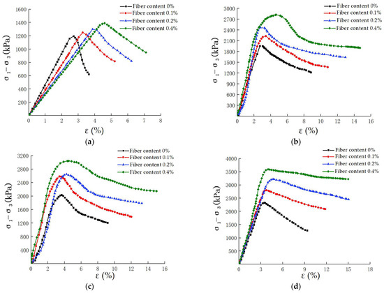
Figure 5.
Stress-strain curves of fiber-cement soil under different confining pressures. (a) confining pressure 0 kPa; (b) confining pressure 100 kPa; (c) confining pressure 200 kPa; (d) confining pressure 400 kPa.
The stress-strain curve trend in Figure 5 was divided into four stages. In the first stage, when the load was small, the stress–strain was linear, which was approximately regarded as a straight line, and this stage was an elastic stage. In the second stage, which was called the yield stage, the stress and strain increased gradually, and the straight line began to bend. In the third stage, which was known as the strengthening stage, the stress and strain gradually increased to the peak value, and the sample underwent plastic failure. In the fourth stage, the stress decreased gradually with the increase in the strain. Great fiber content corresponded to a slow decrease in stress. Greater confining pressure corresponded to a slow decrease in the stress and thus greater residual strength. This stage was the residual strength stage.
3.3. Effect of Polypropylene Fiber Content on Internal Friction Angle and Cohesion
With ((σ1f + σ3f)/2,0) as the center and (σ1f − σ3f)/2 as the radius, the Mohr stress circle and tangent line were drawn. As shown in Figure 6, the shear strength parameters of fiber cement soil under non-consolidation and undrained conditions were obtained. Figure 6 showed that when the fiber was not mixed, the internal friction angle was 25° and the cohesion was 561 kPa. When the fiber content increased from 0.1% to 0.4%, the internal friction angle slowly increased from 31° to 35°, and the cohesion gradually changed from 588 kPa to 658 kPa. This condition showed that when the fiber was added to the soil, the internal friction angle and cohesion of the soil increased slowly because the elastic modulus of polypropylene fiber was greater than the elastic modulus of the soil. When the fiber was added to the soil, it was chaotic and intertwined, and the soil particles formed a network structure, which can inhibit the generation of cracks and improve the cohesion of the soil to a certain extent, thus improving the strength of the solidified body.
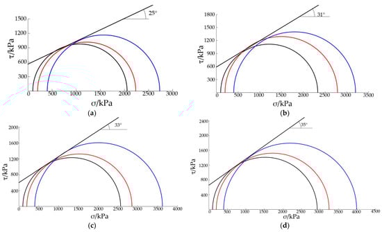
Figure 6.
Molar circle and strength envelope of fiber cement soil with different fiber content. (a) fiber content 0%; (b) fiber content 0.1%; (c) fiber content 0.2%; (d) fiber content 0.4%. Note: the black contour line represents the confining pressure of 100 kPa, the red contour line represents the confining pressure of 200 kPa, and the blue contour line represents the confining pressure of 400 kPa.
3.4. Stress–Strain Curve Fitting of Fiber Cement Soil with Different Curve Equations
The stress–strain curve of the cement solidified body under compression was similar to the stress–strain curve of concrete. As shown in Figure 7, the transverse axis was the relative strain value, that is, the ratio of the actual strain to the strain value corresponding to the peak stress x = ε/εpr, and the longitudinal axis was the relative stress value, that is, the ratio of the actual stress to the peak stress y = σ/σpr.
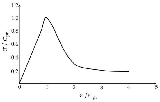
Figure 7.
Stress–strain curve of uniaxial compression specimen.
3.4.1. Fitting Curve of Fiber Cement Soil under Uniaxial Compression
Figure 4 is described in mathematical language:
- When x = 0, y = 0; when x = 1, y = 1 and dy/dx = 0;
- When x ∈ [0, 1), the first derivative dy/dx of the ascending segment of the curve monotonically decreased and there was no inflection point;
- When x → +∞, y → 0, the value range of y was [0, 1];
- d2y/dx2 = 0, x > 1, and there was an inflection point.
With x = 1 taken as the boundary point, the piecewise function was used to fit the samples without confining pressure:
(1) When x ≤ 1, the cubic parabolic equation satisfying 1 and 2 above is
Here, a1, a2, a3, and a4 were the coefficients of the parabolic equation.
With the above 1 integrated into Formula (1), parameters a1, a2, and a4 can be simplified and the expression containing only parameter a3 can be obtained
(2) When x > 1, the hyperbolic equation satisfying 1, 2, 3, and 4 above is
Here, b1, b2, and b3 are coefficients of hyperbolic equations.
According to the boundary conditions, we can deduce that b1 = b3, b2 = 1 − 2b1, after substituting Formula (3) into
With the hyperbolic equation simplified as Formula (5)
When b1 = 0, y = 1, which is the peak state of the curve, the sample was in the ideal plastic state; when b1 → +∞, y = 0, indicating that the sample did not enter the residual strength stage after the peak state of the curve, and the residual strength gradually became zero, resulting in brittle deformation of the sample. Finally, the Origin software was used to fit the curve. Table 7 was the corresponding parameter, and the curve fitting diagram is shown in Figure 8. The value of the adjusted R square was closest to the value of 1, indicating that the fitting effect of the fitting curve was better.
Table 7.
Coefficient table of constitutive equation of soil sample under uniaxial compression.
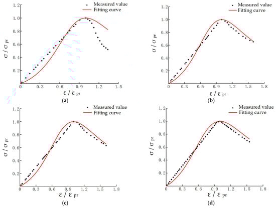
Figure 8.
The measured value and curve fitting diagram of cement soil with different fiber content under uniaxial compression. (a) fiber content 0%; (b) fiber content 0.1%; (c) fiber content 0.2%; (d) fiber content 0.4%.
3.4.2. Fitting Curve of Fiber Cement Soil under Confining Pressure
In 1963, through the stress–strain curve of the triaxial test, Kondner found that the hyperbolic curve can be used as the fitting curve of the stress–strain relationship of soil. The Kondner hyperbolic curve is as follows:
where a and b are constants, σ1 is major principal stress, σ3 is minor principal stress and ε is axial strain.
In this paper, the stress–strain curve under confining pressure was fitted by using the Kondner hyperbolic curve. The triaxial test results were adjusted according to the Kondner hyperbolic curve as follows:
That is, ε/(σ1 − σ3) and ε were linear. In the triaxial test, dσ2 = dσ3 = 0; therefore the tangent modulus was
If ε = 0, Et = E0, then E0 = 1/b, E0 was the initial tangent modulus.
In Figure 5b–d were the stress-strain curves under confining pressure (the confining pressures were 100, 200, and 300 kPa) and had the following characteristics:
- (1).
- The curve was hyperbolic, and the slope increased with the increase in the confining pressure;
- (2).
- In the hardening stage before reaching the peak, the stress velocity gradually slowed down after reaching the peak.
The fitting equation under confining pressure can be established by a hyperbolic function. Bases on the Kondner hyperbolic curve, a new expression was established, where a, b, and c were constants.
Equation (9) indicates that the curve was a parabola. Through curve fitting, the specific parameters were shown in Table 8, curve fitting of fiber cement soil under confining pressure was shown in Figure 9. The value of the adjusted R square was closest to the value of 1, indicating that the fitting effect of the fitting curve was better.
Table 8.
Table of constitutive equation coefficients of fiber-cement soil under confining pressure.
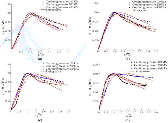
Figure 9.
The measured value and curve fitting diagram of fiber cement soil under confining pressure. (a) fiber content 0%; (b) fiber content 0.1%; (c) fiber content 0.2%; (d) fiber content 0.4%.
4. Study on Macro and Micro Mechanism of Polypropylene Fiber Improving Cement-Soil Strength
4.1. Failure Mode of Fiber Cement Soil under Macroscopic Condition
The failure morphology of fiber cement soil with different fiber content at the same age was shown in Figure 10. The cement dosage is 15%, fiber length was 9 mm. It intuitively showed that under the same conditions, with the increase in the fiber content, the compressive strength increased, the crack width at failure decreased, and the crack form also changed. With the increase in the fiber content, the crack form also developed from a through crack to a small oblique crack. When the fiber content was 0%, the failure of the sample presented obvious brittle failure, showing a penetrating vertical crack with a width of more than 3 mm. In the process of failure, small pieces of samples and soil chips fall out. When the fiber content was 0.1% and 0.2%, with the increase in the fiber content, brittle failure was also significantly improved, with irregular oblique cracks that had a width between 1–3 mm, and the strength was also improved. When the fiber content was 0.4%, the fracture was greatly improved, which was not an obvious oblique crack. The crack width was less than 1 mm, and the strength was the highest under the same condition because, with the addition of polypropylene fiber, the interfacial bonding force between the fiber and the soil particles can be generated, which can resist the deformation caused by specimen failure and improve the toughness of fiber cement soil. The macro-cracks were caused by the poor tensile strength of cement soil. To improve the tensile strength, fiber was added, which can delay the continuous development of cracks through its own unique toughness. With the increase in the fiber content, the fiber bound the cracks together and redistributed the stress through the interface between the fiber and the cement soil, and then generated new microcracks to improve the strength of the solidified body [24,25,26,47].
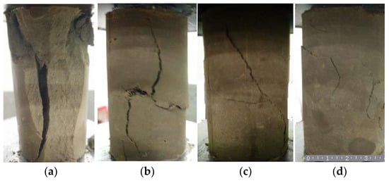
Figure 10.
Failure pattern of fiber cement soil with different fiber content (1:1). (a) fiber content 0%; (b) fiber content 0.1%; (c) fiber content 0.2%; (d) fiber content 0.4%.
4.2. Failure Mode of Fiber Cement Soil under Micro-State
The scanning electron microscope of the cement soil without fiber with cement content of 15% is shown in Figure 11a. It can be seen that the hydration products were wrapped outside the soil particles to form a dense structure, which can improve the compressive strength of the soil. Figure 11b–d shows the cement-soil mixed with fibers (cement dosage was 15% and fiber length was 9 mm). The fibers were distributed in a disorderly manner, forming a network structure, and the hydration products formed by cement were wrapped on the surface of the fibers. These products wrapped the fibers to increase their surface area and provided help for the interfacial friction between soil particles, making the reinforced soil more compact and improving the normal stress and contact area of the fibers. Dispersed fibers also formed a network structure, and soil particles and fibers were agglomerated to connect with each other to form a whole. Soil particles and fibers were mutually constrained so that fiber reinforcement was not easy to crack. When the fiber cement soil was damaged and cracks were generated, the friction force generated by the interface between the cement soil and the fiber was combined with the characteristics of the fiber itself when the fiber was forced to slide or be pulled out to improve the tension between the fiber and the cement soil. The toughness of the reinforced soil was thus improved so that the fiber cement soil still had a certain bearing capacity after the cracks were generated [20].
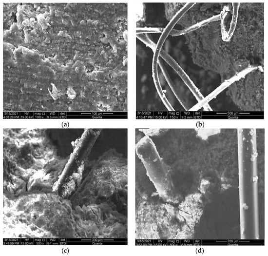
Figure 11.
SEM chart of fiber cement soil. (a) fiber content 0%; (b) fiber content 0.1%; (c) fiber content 0.2%; (d) fiber content 0.4%.
Micro-tests showed that the mutual modes between soil particles and fibers were contact, bending, and interleaving. These three modes provided the interfacial shear stress between soil particles and fibers and the tensile stress of fibers for the reinforced soil. The movement of soil particles was limited by shear stress and tensile stress, and the shear strength and deformation resistance of the specimen were improved [14,47].
5. Conclusions
- Through range analysis, the UCS influencing factors of fiber cement soil from high to low were: cement dosage, fiber content, and fiber length; through the orthogonal test, the ratio of the maximum UCS of fiber cement soil was obtained as follows: the cement dosage was 18%, the fiber content was 0.4%, and the fiber length was 3 mm. The UCS could reach 1.63 MPa, which was 4.8 times that of the sample without fiber and the cement dosage was 9%.
- When the cement dosage was 15%, the failure mode of cement solidified soil without fiber was brittle failure, and when cement dosage was 15%, fiber length was 9 mm, the failure mode of cement solidified soil with fiber was plastic failure.
- The UU test showed that when the cement dosage was 15% and the fiber length was 9 mm, with the increase in the fiber content, not only the peak stress and failure strain of fiber-cured soil were improved, but also the cohesion and internal friction angle were gradually increased.
- The stress-strain curves of fiber cement soil and concrete under uniaxial compression were similar, and the equation was established and fitted by using the relative stress-relative strain relationship. The fiber cement soil under confining pressure was established by hyperbolic function and was fitted by Kondner hyperbolic curve.
- The failure mode of fiber cement soil showed that when the cement dosage was 15% and the fiber length was 9 mm, with the increase in the fiber content, the cracks in the failure of cement soil were gradually reduced, indicating that fiber can effectively improve the strength and deformation of cement soil.
In this paper, the strength and deformation characteristics of fiber cement soil were studied through the UCS test and UU test. However, there was no research on subsequent tests of fiber cement soil, such as water stability and dry wet cycle test, and there was also a lack of research on tensile property test of fiber cement soil. In addition, we can apply dynamic load to the sample through the true triaxial test, simulate the load action of fiber cement soil in the process of vehicle operation, and study the applicability of fiber cement soil in subgrade reinforcement.
Author Contributions
Conceptualization, S.L. and S.Z.; methodology, Z.H. and D.F.; validation, X.Y.; formal analysis, Y.X.; investigation, Y.X.; data curation, X.Y. and D.F.; writing—original draft preparation, X.Y.; writing—review and editing, S.L. and Z.H.; supervision, S.Z.; project administration, S.L. All authors have read and agreed to the published version of the manuscript.
Funding
This research was funded by the National Natural Science Foundation of China, grant number No. 52078142, Natural Science Foundation of Guangdong Province, grant number No. 2022A1515011047, Science and Technology Program of Guangzhou, China, grant number No. 202002030194.
Institutional Review Board Statement
Not applicable.
Informed Consent Statement
Not applicable.
Data Availability Statement
The data used to support the findings of this study are included in the article.
Conflicts of Interest
The authors declare no conflict of interest.
References
- Chao, W.; Chen, Y. Analysis of sliding failure mechanism and treatment for taihua a highway embankment slope over soft soils. Chin. J. Rock Mech. Eng. 2007, 7, 1504–1510. [Google Scholar]
- Zhang, W.; Lin, D.; Chen, Y.; Zhou, M. Stability analysis of filled embankment laid on soft subsoil compacted with sand-stone pile. Railw. Eng. 2007, 11, 46–49. [Google Scholar]
- Wu, H. Research of the Settlement Prediction on the Soft Soil Foundation in Yantai Region; Tianjin University: Tianjin, China, 2015. [Google Scholar]
- Ng, K.S. Tensile Behavior of Fiber Reinforced Cemented Soil: A Short Review. In Proceedings of the Advances in Civil Engineering and Science Technology; Goh, L.D., Ng, K.S., Hassan, S.H., Woo, Y.P., Basri, M.H.H., Hamid, M.S.A., Eds.; American Institute of Physics: Melville, NY, USA, 2018; Volume 2020, p. 020001. [Google Scholar]
- Sadat Ali Khan, Z.A.; Afiya, A. Performance of FRC Produced with Mineral Admixtures and Waste Plastic Fibers Under Sulfate Attack. IJITEE 2019, 8, 1101–1107. [Google Scholar] [CrossRef]
- Venkateswararao, T.; Prasad, R.R.; Prasad, D.S.; Ram, D.A. Utilization of Fiber Reinforcement Materials in Flexible Pavement Construction. IJITEE 2019, 8, 160–165. [Google Scholar] [CrossRef]
- Fatahi, B.; Khabbaz, H.; Fatahi, B. Mechanical Characteristics of Soft Clay Treated with Fibre and Cement. Geosynth. Int. 2012, 19, 252–262. [Google Scholar] [CrossRef]
- Zhou, N.; Ouyang, S.; Cheng, Q.; Ju, F. Experimental Study on Mechanical Behavior of a New Backfilling Material: Cement-Treated Marine Clay. Adv. Mater. Sci. Eng. 2019, 2019, 1261694. [Google Scholar] [CrossRef]
- Anggraini, V.; Asadi, A.; Huat, B.B.K.; Nahazanan, H. Effects of Coir Fibers on Tensile and Compressive Strength of Lime Treated Soft Soil. Measurement 2015, 59, 372–381. [Google Scholar] [CrossRef]
- Correia, A.A.S.; Venda Oliveira, P.J.; Custódio, D.G. Effect of Polypropylene Fibres on the Compressive and Tensile Strength of a Soft Soil, Artificially Stabilised with Binders. Geotext. Geomembr. 2015, 43, 97–106. [Google Scholar] [CrossRef]
- Kumar, A.; Gupta, D. Behavior of Cement-Stabilized Fiber-Reinforced Pond Ash, Rice Husk Ash-Soil Mixtures. Geotext. Geomembr. 2016, 44, 466–474. [Google Scholar] [CrossRef]
- Cheng, Q.; Zhang, J.; Zhou, N.; Guo, Y.; Pan, S. Experimental Study on Unconfined Compression Strength of Polypropylene Fiber Reinforced Composite Cemented Clay. Crystals 2020, 10, 247. [Google Scholar] [CrossRef]
- Jayalin, D.; Vellingiri, N.; Raman, S.J. Experimental Research on Durability Properties of High Volume Fly Ash Concrete with Polypropylene Fibre. IJITEE 2019, 8, 1039–1042. [Google Scholar] [CrossRef]
- Liu, J.; Hou, T.; Luo, Y.; Cui, Y. Experimental Study on Unconsolidated Undrained Shear Strength Characteristics of Synthetic Cotton Fiber Reinforced Soil. Geotech. Geol. Eng. 2020, 38, 1773–1783. [Google Scholar] [CrossRef]
- Liu, C.; Lv, Y.; Yu, X.; Wu, X. Effects of Freeze-Thaw Cycles on the Unconfined Compressive Strength of Straw Fiber-Reinforced Soil. Geotext. Geomembr. 2020, 48, 581–590. [Google Scholar] [CrossRef]
- Wu, Y.; Li, Y.; Niu, B. Assessment of the Mechanical Properties of Sisal Fiber-Reinforced Silty Clay Using Triaxial Shear Tests. Sci. World J. 2014, 2014, 436231. [Google Scholar] [CrossRef]
- Madhavi Latha, G.; Nandhi Varman, A.M. Static and Cyclic Load Response of Reinforced Sand through Large Triaxial Tests. JGS Spec. Publ. 2016, 2, 2342–2346. [Google Scholar] [CrossRef]
- Abdi, M.R.; Arjomand, M.A. Pullout Tests Conducted on Clay Reinforced with Geogrid Encapsulated in Thin Layers of Sand. Geotext. Geomembr. 2011, 29, 588–595. [Google Scholar] [CrossRef]
- Chen, X.; Zhang, J.; Li, Z. Shear Behaviour of a Geogrid-Reinforced Coarse-Grained Soil Based on Large-Scale Triaxial Tests—ScienceDirect. Geotext. Geomembr. 2014, 42, 312–328. [Google Scholar] [CrossRef]
- Tang, C.; Shi, B.; Gao, W.; Chen, F.; Cai, Y. Strength and Mechanical Behavior of Short Polypropylene Fiber Reinforced and Cement Stabilized Clayey Soil. Geotext. Geomembr. 2007, 25, 194–202. [Google Scholar] [CrossRef]
- Li, L.; Zhang, J.; Xiao, H.; Hu, Z.; Wang, Z. Experimental Investigation of Mechanical Behaviors of Fiber-Reinforced Fly Ash-Soil Mixture. Adv. Mater. Sci. Eng. 2019, 2019, 1050536. [Google Scholar] [CrossRef]
- Tang, C.-S.; Shi, B.; Cui, Y.-J.; Liu, C.; Gu, K. Desiccation Cracking Behavior of Polypropylene Fiber-Reinforced Clayey Soil. Can. Geotech. J. 2012, 49, 1088–1101. [Google Scholar] [CrossRef]
- Liu, Y.; Zhou, J.; Wu, D.; Kang, T.; Liu, A. Bond Behavior of Recycled Fiber Recycled Concrete with Reinforcement after Freeze-Thaw Cycles. Crystals 2021, 11, 1506. [Google Scholar] [CrossRef]
- Jamsawang, P.; Voottipruex, P.; Horpibulsuk, S. Flexural Strength Characteristics of Compacted Cement-Polypropylene Fiber Sand. J. Mater. Civ. Eng. 2015, 27, 04014243. [Google Scholar] [CrossRef]
- Sukontasukkul, P.; Jamsawang, P. Use of Steel and Polypropylene Fibers to Improve Flexural Performance of Deep Soil–Cement Column. Constr. Build. Mater. 2012, 29, 201–205. [Google Scholar] [CrossRef]
- Cristelo, N.; Cunha, V.M.C.F.; Topa Gomes, A.; Araújo, N.; Miranda, T.; de Lurdes Lopes, M. Influence of Fibre Reinforcement on the Post-Cracking Behaviour of a Cement-Stabilised Sandy-Clay Subjected to Indirect Tensile Stress. Constr. Build. Mater. 2017, 138, 163–173. [Google Scholar] [CrossRef]
- Ekinci, A.; Abki, A.; Mirzababaei, M. Parameters Controlling Strength, Stiffness and Durability of a Fibre-Reinforced Clay. Int. J. Geosynth. Ground Eng. 2022, 8, 6. [Google Scholar] [CrossRef]
- Liu, Y.; Pang, J.; Chen, Q.; Yao, W. Study on Mechanical Properties and Pore Structure of Hybrid Fiber Reinforced Rubber Concrete. Crystals 2021, 11, 1307. [Google Scholar] [CrossRef]
- Gao, L.; Hu, G.; Xu, N.; Fu, J.; Xiang, C.; Yang, C. Experimental Study on Unconfined Compressive Strength of Basalt Fiber Reinforced Clay Soil. Adv. Mater. Sci. Eng. 2015, 2015, 561293. [Google Scholar] [CrossRef]
- Rui-min, C.; Wen-bin, J.; Xiao-fang, Z.; Ze-hua, F. Experimental study on performance of sludge stabilized by CSFG-FR synergy. Rock Soil Mech. 2022, 43, 1020–1030. [Google Scholar] [CrossRef]
- Wang, H.; Liu, C. Effect of Fiber Content on Mechanical Properties of Microbial Solidified Marine Sand. Journal of Yantai Uni-versity (Natural Science and Engineering Edition). Available online: https://kns.cnki.net/kcms/detail/detail.aspx?dbcode=CAPJ&dbname=CAPJLAST&filename=YTSZ20220601001&uniplatform=NZKPT&v=n_uNnZJCz_IRjCeIFvAzjz2umj82ANvD4lzBX5NPuHaUWCo6L9drJbyVWMDI4BxL (accessed on 12 July 2022).
- Ma, K.; Liu, j.; Jiang, C.; Ma, X.; Huang, L.; He, C.; Qi, C. Compressive and tensile strength of polymer-based fiber composite sand. J. Cent. South Univ. 2022, 29, 528–545. [Google Scholar] [CrossRef]
- Wang, Z.; Deng, J.; Mei, L.; Wang, B. Experimental study on static characteristics of cement-solidified dredged soil reinforced by polyvinyl alcohol fiber. J. Jiangsu Univ. Sci. Technol. 2021, 35, 104–108. [Google Scholar]
- Wang, Y.; Zhou, M.; Xiang, Y.; Dong, Y.; Hou, H. Effect of Adding Coconut Fiber on Moisture Loss and Cracking Properties of Bottom Ash Based Geopolymer-Soil Solidified Blocks; Environmental Engineering: Beijing, China, 2020; pp. 1–11. Available online: http://kns.cnki.net/kcms/detail/11.2097.X.20220524.2026.010.html (accessed on 24 June 2022).
- Hao, J.; Zhang, H.; Li, G.; Liu, Z.; Huang, J.; Jiang, Z. Strength and cracking characteristics of expansive soil improved by fly ash and sisal fiber. J. Railw. Sci. Eng. 2022, 1–9. [Google Scholar] [CrossRef]
- Siswanto, J.; Latifah, K.; Supriyadi, B.; Rochim, A.; Alzami, F. The Relation of Compressive Strength and Tensile Strength of Bamboo Fibber for Soil Stabilization. J. Phys. Conf. Ser. 2020, 1517, 012075. [Google Scholar] [CrossRef]
- Jiang, P.; Chen, Y.; Li, N.; Zhou, L.; Pu, S.; Wang, W. Strength Properties and Microscopic Mechanism of Lime and Fly Ash Modified Expandable Poly Styrene Lightweight Soil Reinforced by Polypropylene Fiber. Case Stud. Constr. Mater. 2022, 17, e01250. [Google Scholar] [CrossRef]
- Li, Y.; Thielemans, W.; Yuan, Q.; Li, J. PVA Fiber Reinforced Cement Composites with Calcined Cutter Soil Mixing Residue as a Partial Cement Replacement. Constr. Build. Mater. 2022, 326, 126924. [Google Scholar] [CrossRef]
- Shen, Y.; Tang, Y.; Yin, J.; Li, M.; Wen, T. An Experimental Investigation on Strength Characteristics of Fiber-Reinforced Clayey Soil Treated with Lime or Cement. Constr. Build. Mater. 2021, 294, 123537. [Google Scholar] [CrossRef]
- Xiao, Y.; Tong, L.; Che, H.; Guo, Q.; Pan, H. Experimental Studies on Compressive and Tensile Strength of Cement-Stabilized Soil Reinforced with Rice Husks and Polypropylene Fibers. Constr. Build. Mater. 2022, 344, 128242. [Google Scholar] [CrossRef]
- Lu, L.; Liu, C.; Qu, S.; Zhang, M. Experimental Study on the Mechanical and Hydraulic Behaviour of Fibre-Reinforced Cemented Soil with Fly Ash. Constr. Build. Mater. 2022, 321, 126374. [Google Scholar] [CrossRef]
- Gong, J.; Ma, Y.; Fu, J.; Hu, J.; Ouyang, X.; Zhang, Z.; Wang, H. Utilization of Fibers in Ultra-High Performance Concrete: A Review. Compos. Part B Eng. 2022, 241, 109995. [Google Scholar] [CrossRef]
- Tang, C.-S.; Shi, B.; Zhao, L.-Z. Interfacial Shear Strength of Fiber Reinforced Soil. Geotext. Geomembr. 2010, 28, 54–62. [Google Scholar] [CrossRef]
- Liu, J.; Chang, D.; Yu, Q. Influence of Freeze-Thaw Cycles on Mechanical Properties of a Silty Sand. Eng. Geol. 2016, 210, 23–32. [Google Scholar] [CrossRef]
- Li, C.; Austin, U. Validation of Discrete Framework for Fiber Reinforcement. Available online: https://sites.utexas.edu/zornberg/files/2022/03/Li_Zornberg_2003.pdf (accessed on 24 June 2022).
- Zainal, S.M.I.S.; Hejazi, F.; Aziz, F.N.A.A.; Jaafar, M.S. Constitutive Modeling of New Synthetic Hybrid Fibers Reinforced Concrete from Experimental Testing in Uniaxial Compression and Tension. Crystals 2020, 10, 885. [Google Scholar] [CrossRef]
- Donkor, P.; Obonyo, E. Compressed Soil Blocks: Influence of Fibers on Flexural Properties and Failure Mechanism. Constr. Build. Mater. 2016, 121, 25–33. [Google Scholar] [CrossRef]


Publisher’s Note: MDPI stays neutral with regard to jurisdictional claims in published maps and institutional affiliations. |
© 2022 by the authors. Licensee MDPI, Basel, Switzerland. This article is an open access article distributed under the terms and conditions of the Creative Commons Attribution (CC BY) license (https://creativecommons.org/licenses/by/4.0/).