Article

Study on Static Analytical Method of Multi-Tower Self-Anchored Suspension Bridge

1
College of Civil Engineering, Fuzhou University, Fuzhou 350108, China
2
Railway Bridge Science Research Institute Co., Ltd., Wuhan 430034, China
3
Fuzhou Traffic Construction Group Co., Ltd., Fuzhou 350000, China
*
Author to whom correspondence should be addressed.
Appl. Sci. 2022, 12(17), 8499; https://doi.org/10.3390/app12178499
Submission received: 14 July 2022 / Revised: 22 August 2022 / Accepted: 23 August 2022 / Published: 25 August 2022

Abstract

:
Based on the deflection theory and the characteristics of multi-tower self-anchored suspension bridges, considering the influence of longitudinal stiffness of main tower and bending effect of stiffening beam, the equilibrium differential equation and deformation coordination equation of multi-tower self-anchored suspension bridges are established. By “replacing beam” method, the practical calculation formula of internal force and deformation of multi-tower self-anchored suspension bridge was deduced, and the corresponding calculation program was implemented. The correctness of the analytical method and calculation program was verified by an example. The analytical method of static analysis of multi-tower self-anchored suspension bridges established in this paper can theoretically explain the mechanical characteristics of the structure, and the calculation method has a clear calculation flow. The internal force and deformation of the structure under live load can be approximately calculated only by inputting the main design parameters of the structure, which is suitable for structural design and parameter analysis of multi-tower self-anchored suspension bridge.

1. Introduction

A suspension bridge is mainly composed of a main cable, pylon, stiffening beam and suspension cable. Because of its good mechanical performance, strong spanning ability and beautiful outline, it is widely used. In 1883, the Brooklyn Bridge built in the US was regarded as the first modern suspension bridge [1]. In 1915, German engineers built the Cologne—Deutz Bridge on the Rhine River, with a main span of 184.5 m, which became the first long-span, self-anchored suspension bridge in the world [2]. Since then, self-anchored suspension bridges have gradually diversified in terms of span, cable arrangement and types of stiffening beams. Landmark bridges, such as the Konohana Bridge, the Yongjong Grand Bridge and Auckland Bay New Bridge have been successively built [3,4,5]. Multi-tower self-anchored suspension bridge combines the characteristics of single-tower and double-tower self-anchored suspension bridges and ground-anchored suspension bridges. Multi-tower self-anchored suspension bridges have better adaptability to terrain and site conditions, more flexible layout and more beautiful linear appearance. In China, the Fuzhou Luozhou Bridge, built in 2013, became the first multi-tower self-anchored suspension bridge in the world [6]. In 2016, the span of the Yinchuan Binhe Yellow River Bridge, a multi-tower, self-anchored suspension bridge, exceeded 200 m [7]. In 2022, the Fenghuang Yellow River Bridge was built in Jinan, China, with a span of 70 m + 168 m + 2 × 428 m + 168 m + 70 m, making it the largest three-tower, self-anchored suspension bridge in the world today [8].
In recent decades, scholars have conducted extensive research on the analytical calculation theory of self-anchored suspension bridges and obtained many significant results. John A. and David P. [2] compare the analysis theory of suspension bridges with finite element analysis, and think that the deflection theory can be used for preliminary approximate analysis of self-anchored suspension bridge. Ho-Kyung Kim et al. [3] analyzed the empty cable state and completed cable state of the main cable of self-anchored suspension bridges and the nonlinear form-finding calculation method proposed by them has higher accuracy than the previous calculation and analysis. Shi Lei et al. [9] considered the influence of the axial compressive strain energy of stiffened beam and obtained the basic differential equation of deflection theory of self-anchored suspension bridges. Shen et al. [10] established an analytical algorithm and calculation program of deflection theory of self-anchored suspension bridge with single tower and two towers by force method. Based on the deflection theory, Tang Mian [11] deduced the practical formula of internal force and deformation of stiffening girder of self-anchored suspension bridge and established the calculation equation based on the deflection theory. Based on the energy principle, Huang and Ye [12] deduced the basic equations suitable for common self-anchored suspension bridges with two towers and put forward a simplified calculation method. For the two-tower self-anchored suspension bridge whose main cable is a three-dimensional curve, Sun et al. [13] put forward the coordinate iteration method to find the shape. An analytical algorithm by Zhang et al. [14] put forward based on the segmented catenary theory to obtain the reasonable range of the stiffness of the center tower of the ground-anchored three-tower suspension bridge with unequal main spans.
Most of the above analytical methods of multi-tower self-anchored suspension bridges adopt deflection theory or calculation methods based on deflection theory. From the analysis results, it is appropriate to use deflection theory to approximate the self-anchored suspension bridge. However, the related studies are only aimed at the common single-tower or two-tower self-anchored suspension bridges, and the longitudinal stiffness of the main tower is not considered when the deflection theory is used for analysis. For the analysis of multi-tower self-anchored suspension bridge, it is necessary to consider the influence of the longitudinal stiffness of the main tower on the structural mechanical behavior. Therefore, based on the deflection theory, considering the influence of the longitudinal stiffness of the main tower and the bending effect of the stiffening beam, this paper established the equilibrium equation and the deformation coordination equation of the multi-tower self-anchored suspension bridge, deduced the formula of the structural internal force and deformation of the multi-tower self-anchored suspension bridge and implemented the corresponding calculation program.

2. Establishment of Basic Differential Equation

According to the elastic theory [15], the geometric shape of the main cable of suspension bridge is quadratic parabola. The dead load is completely borne by the main cable. The geometric shape and length of the main cable do not change due to the live load acting on the bridge deck. The superposition principle is applicable to it. However, the elastic theory does not consider the contribution of the dead load to the vertical stiffness of the structure and the nonlinear influence of the large displacement of the structure, so the calculation results of the elastic theory are conservative. In the deflection theory [16], the geometric shape of the main cable of suspension bridge will change due to live load when it is balanced under dead load. The elongation of the main cable due to live load should also be considered. Because some idealized assumptions are adopted, the calculation results have certain approximation.

2.1. Basic Assumption

In order to study the analytical calculation method and establish its basic differential equation of multi-tower self-anchored suspension bridge, the following basic assumptions are made:
(1)
The main cable is only in tension, but does not bear the bending moment. The geometric shape of the main cable is a quadratic parabola due to the horizontal uniform load along the span.
(2)
The slings are densely distributed vertically along the whole bridge span, which is regarded as a “membrane” that only provides vertical resistance, regardless of its elongation and inclination under live load; that is, the deformation of the main cable and the stiffening beam is the same.
(3)
In each span, the stiffened beam is a straight beam with equal cross section; that is, the cross section characteristics and material parameters are constant.
(4)
Ignore the shear deformation of stiffened beams.
(5)
Consider the longitudinal stiffness of the main tower and the influence of unbalanced horizontal forces of main cables on both sides of the tower top on the horizontal displacement of the main tower.

2.2. Derivation of Basic Equation

Firstly, this paper deduced the basic equation of three-tower self-anchored suspension bridge, and its structural layout is shown in Figure 1.
The geometric shape of the main cable under dead load is quadratic parabola, so the vertical curve equation of each main cable can be expressed as Equation (1).
y i = 4 f i l i 2 x i ( l i x i ) i = 1 , 2 , 3 , 4
where: li = each span length, fi = rise of each span main cable, xi = longitudinal position of main cable, yi = the vertical curve function of the main cable about xi.
When the dead load uniformly acts on the whole bridge and the temperature difference is not included, the horizontal tension of the main cable can be regarded as a constant. The horizontal displacement of each tower top in the longitudinal bridge direction will not occur. Due to the longitudinal stiffness of the main tower, under the action of live load and temperature change, the horizontal tension of the main cable under live load can still be regarded as a constant in each span, but it is not equal for each span. In order to coordinate the unbalanced horizontal forces of the main cables on both sides of the tower, horizontal displacements of different sizes will occur at the top of each tower to achieve a balanced state of stress and deformation of the structure.

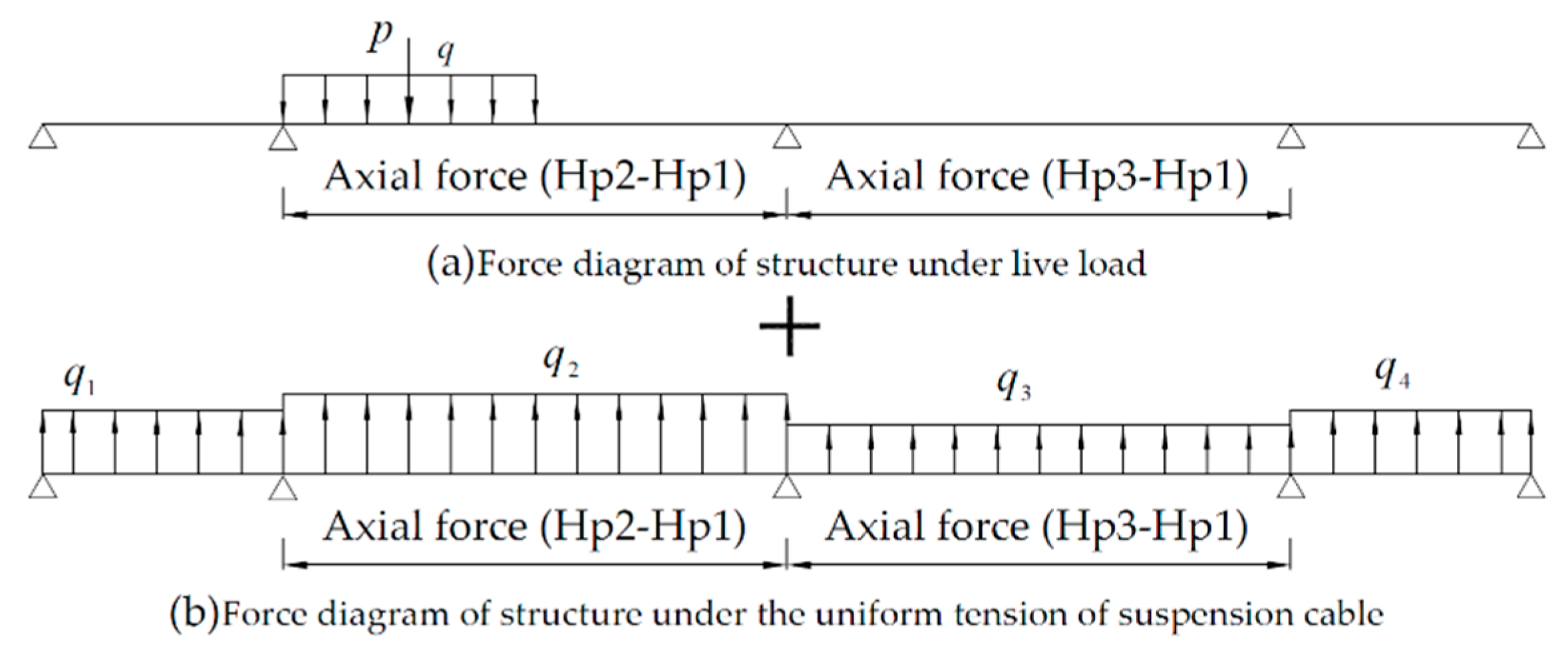
2.3. Equilibrium Differential Equation

Considering the influence of the longitudinal stiffness of the main tower, the horizontal tension of the main cable under live load is not equal. Under the action of dead load, the micro-segment balance equation of the main cable of the left span is as follows:
H g 1 d 2 y 1 dx 2 = g c + f g 1  
where: Hg1 = horizontal tension of main cable under dead load. y1 = the vertical curve function of the main cable about x1. gc = the dead weight of the main cable evenly distributed along the span; fg1 = the main cable gets tension of each micro-segment of main cable when the cable force of the suspension cable is transmitted to the main cable.
Assuming that the vertical curve of the stiffening beam under dead load is z(x), and the axial force is Hg1, the equilibrium equation of the left span stiffening beam is Equation (3).
EI d 4 z dx 4 + H g 1   d 2 z dx 2 = g b 1 f g 1
where: EI = the bending stiffness of stiffening beam; gb1 = the dead load magnitude of stiffening beam.
Substituting Equation (2) into Equation (3) to obtain the elastic Equation (4) of stiffened beam under dead load.
EI 1 d 4 z dx 4 + H g 1   d 2 z dx 2 d 2 y 1 dx 2 = g b 1 + g c
Under the action of live load p i x , the vertical displacement of the stiffening beam and main cable on the left side span is η 1 x , and the cable force of the suspension cable is f 1 . The horizontal tension of the main cable is H 1 = H g 1 + H p 1 , of which the horizontal tension of the main cable under live load is H p 1 . Therefore, the micro-segment balance equation of the main cable under the combined action of dead load and live load is Equation (5).
H 1   d 2 z dx 2 + d 2 η 1 dx 2 = g c + f 1
The micro-segment equilibrium equation of stiffened beam under the combined action of dead load and live load is Equation (6).
EI 1 d 4 z dx 4 + d 4 η 1 dx 4 + H 1   d 2 z dx 2 + d 2 η 1 dx 2 = g b 1 + p 1 x f 1
Substituting Equation (5) into Equation (6) to obtain the elastic equation of stiffened beam under the combined action of dead load and live load, as shown in Equation (7).
EI 1 d 4 z dx 4 + d 4 η 1 dx 4 + H 1   d 2 z dx 2 d 2 y 1 dx 2 = g b 1 + p 1 x g c  
Subtract Equation (7) from Equation (4) to obtain the balance differential equation of the left span stiffened beam caused by live load, as shown in Equation (8).
EI 1 d 4 η 1 dx 4 = p 1 x + H p 1   d 2 y 1 dx 2 H p 1   d 2 z dx 2  
Using the same derivation method above, the equilibrium differential equations of other stiffened beams can be obtained. In addition, under normal circumstances, self-anchored suspension bridges usually adopt longitudinal floating system; that is, stiffening beams are not constrained in the longitudinal direction of the bridge. In the equilibrium state, H p 1 = H p 4 . Therefore, the balance differential equation of each span stiffening beam of three-tower self-anchored suspension bridge is shown in Equation (9).
EI 1 d 4 η 1 dx = p 1 ( x ) + H p 1 d 2 y 1 dx 2 H p 1 d 2 z dx 2 EI 2 d 4 η 2 dx 4 = p 2 ( x ) + H p 2 d 2 y 2 dx 2 H p 1 d 2 z dx 2 + H p 2 H p 1 d 2 η 2 dx 2 EI 3 d 4 η 2 dx 4 = p 3 ( x ) + H p 3 d 2 y 3 dx 2 H p 1 d 2 z dx 2 + H p 3 H p 1 d 2 η 3 dx 2 EI 4 d 4 η 4 dx 4 = p 4 ( x ) + H p 1 d 2 y 4 dx 2 H p 1 d 2 z dx 2
where: η1, η2, η3, η4 = the deflection of each span stiffening beam. p1(x), p2(x), p3(x), p4(x) = the live load magnitude of each span stiffening beam. Hp1, Hp2, Hp3 = the horizontal tension of main cable. z = the dead load. x = longitudinal position of stiffening beam.
When the stiffness of the main tower is not considered, the equilibrium differential equation of the deflection theory of self-anchored suspension bridge is linear [17], as shown in Equation (10).
EI d 4 η dx 4 = p x + H p d 2 y dx 2 H p d 2 z dx 2  
where: η = the deflection of stiffening beam. p(x) = the live load magnitude of stiffening beam. Hp = the horizontal tension of main cable. z = the dead load. x = longitudinal position of stiffening beam.
For a multi-tower self-anchored suspension bridge, the equilibrium differential equation becomes nonlinear after considering the longitudinal stiffness of the main tower. If the stiffness of the main tower is not considered, that is, the horizontal tensile forces of the main cables across each span are equal, then Equation (9) is equivalent to Equation (10).
For the ground-anchored suspension bridge, the deflection theoretical equilibrium differential equation obtained without considering the stiffness of the main tower is nonlinear [18], as shown in Equation (11).
EI d 4 η dx 4 = p x + H p d 2 y dx 2 H d 2 η dx 2  
where: η = the deflection of stiffening beam. p(x) = the live load magnitude of stiffening beam. Hp = the horizontal tension of main cable. z = the dead load. x = longitudinal position of the stiffening beam.
From Equation (9) and Equation (11), under the same other conditions, the horizontal tension of the main cable of suspension bridge under dead load and live load is much larger than that under live load. Therefore, the nonlinear degree of Equation (9) should be lower than that of Equation (11).

2.4. Deformation Compatibility Equation

There are seven unknowns in the balance differential Equation (9) of the three-tower self-anchored suspension bridge, such as η 1 , η 2 , η 3 , η 4 , H p 1 , H p 2   and   H p 3 . Thus, three deformation compatibility equations are needed to solve the problem. In the deformation coordination equation of multi-tower self-anchored suspension bridge, the longitudinal horizontal displacement of the main tower top and the axial compression deformation of the stiffening girder should be considered. According to the deformation coordination conditions of three-tower self-anchored suspension bridge, three deformation coordination equations can be established.
The horizontal projection shortening between the anchor points at both ends of the main cable is the axial compression of the stiffening beam, as shown in Equation (12).
i = 1 4 ( H pi E c A c 0 l i dx cos 3 φ ± α t t 0 l i dx cos 2 φ 0 l i dy i dx d η i = Δ  
The relative displacement of the top of the left tower and the middle tower is the horizontal projection distance variation of the main cable of the left main span, as shown in Equation (13).
H p 2 E c A c 0 l 2 dx cos 3 φ ± α t t 0 l 2 dx cos 2 φ 0 l 2 dy 2 dx d η 2 = Δ 2 Δ 1  
The relative displacement between the middle tower and the top of the right tower is the horizontal projection distance variation of the main cable of the right main span, as shown in Equation (14).
H p 3 E c A c 0 l 3 dx cos 3 φ ± α t t 0 l 3 dx cos 2 φ 0 l 3 dy 3 dx d η 3 = Δ 3 Δ 2  
where: EcAc = the axial stiffness of the main cable. Φ = the horizontal inclination angle of the main cable, cos φ = dx ds . α t t = the expansion coefficient of main cable temperature line; t = the main cable temperature change; ∆ = the axial compression of the stiffening beam; ∆1 = he horizontal displacement of the left tower top; ∆2 = the horizontal displacement of the middle tower top; ∆3 = the horizontal displacement of the right tower top.
The left three items of Equations (12) to (14) respectively indicate the change of horizontal projection distance of the main cable caused by the stress, temperature change and deflection of the main cable.
Compression of stiffening beam between anchorage points at both ends of main cable is negative, as shown in Equation (15).
Δ = H p 1 i = 1 4 l i E i A i ± i = 1 4 l i α tbi · t bi  
where: EiAi = the axial stiffness of each span stiffening beam. α tbi = the thermal linear expansion coefficient of each span stiffening beam. t bi = the temperature change of each span stiffening beam.
Therefore, only the influence of the horizontal unbalance force of the main cables on both sides of each tower top on the horizontal displacement of the tower top was considered, and the bending effect caused by the vertical force of the tower top is ignored. The horizontal force balance equation of the main tower is shown in Equation (16).
H p 2 H p 1 = k 1 Δ 1 H p 3 H p 2 = k 2 Δ 2 H p 1 H p 3 = k 3 Δ 3  
where: k1, k2 and k3 = the longitudinal stiffness of the three tower, respectively. The horizontal displacement ∆i of the tower top takes the right direction as the positive direction. Hp1, Hp2 and Hp3 = the horizontal tension of main cable.
Substituting Equations (15) and (16) into Equations (12)–(14) respectively, the deformation coordination equation of three-tower four-span self-anchored suspension bridge is obtained as Equation (17).
{ ( L S 1 + L S 4 E c A c + 1 K 1 + 1 K 3 + i = 1 4 l i E i A i ) · H p 1 + 1 K 1 · H p 2 + 1 K 3 · H p 3 = F η 1 ρ 1 + F η 4 ρ 4 ± α t t L T 1 + L T 4 ± i = 1 4 l i · α tbi · t bi 1 K 1 · H p 1 + L S 2 E c A c + 1 K 1 + 1 K 2 · H p 2 + 1 K 2 H p 3 = F η 2 ρ 2 ± α t · t · L T 2 1 K 3 · H p 1 + 1 K 2 · H p 2 + L S 3 E c A c + 1 K 2 + 1 K 3 · H p 3 = F η 3 ρ 3 ± α t · t · L T 3
where: let 0 l i dx cos 3 φ = L Si , 0 l i dx cos 2 φ = L Ti , ρ i = 1 d 2 y i dx 2 = l i 2 8 f i and they are all quantities related to the geometry of the main cable; 0 l i η i dx = F η i is the area of deflection curve. EiAi = the axial stiffness of each span stiffening beam. α tbi = the thermal linear expansion coefficient of each span stiffening beam. t bi = the temperature change of each span stiffening beam. i = 1, 2, 3 and 4. EcAc = the axial stiffness of the main cable. k1, k2 and k3 = the longitudinal stiffness of the three tower, respectively.

2.5. Expansion of the Equation

Compared with the three-tower self-anchored suspension bridge, the self-anchored suspension bridge with more than three main towers has more intermediate towers and main spans, but they are similar in terms of structural stress mechanism and deformation. Therefore, according to the same derivation idea, the Equation (9) can be extended to obtain the basic equation expression 18 of the multi-tower self-anchored suspension bridge with n main towers.
{ EI 1 d 4 η 1 dx 4 = p 1   x + H p 1   d 2 y 1 dx 2 H p 1   d 2 z dx 2 EI 2 d 4 η 2 dx 4 = p 2   x + H p 2   d 2 y 2 dx 2 H p 1   d 2 z dx 2 + H p 2 H p 1 d 2 η 2 dx 2 EI n 1 d 4 η n 1 dx 4 = p n 1   x + H p n 1   d 2 y 2 dx 2 H p 1   d 2 z dx 2 + H p n 1 H p n 2 d 2 η n 1 dx 2 EI n d 4 η n dx 4 = p n   x + H pn   d 2 y n dx 2 H p 1   d 2 z dx 2 + H pn H p 1 d 2 η n dx 2 EI n + 1 d 4 η n + 1 dx 4 = p n + 1   x + H p 1   d 2 y n + 1 dx 2 H p 1   d 2 z dx 2
Equation (18) has n + 1 equations, which are the equilibrium differential equations of stiffened beams with n − 1 main spans and 2 side spans. Among them, there are 2n + 1 unknowns: deflection ( η 1 , η 2 , η n + 1 ) of each span stiffening beam and horizontal tension ( H p 1 , H p 2 , H Pn ) of each span main cable under live load.
Similarly, according to the deformation coordination conditions of the corresponding multi-tower self-anchored suspension bridge structure, the required N deformation coordination equations can be obtained. Deformation compatibility equations include two types, such as the shortening of horizontal projection between anchor points at both ends of the main cable equal to the axial compression of the stiffening beam and the relative displacement of the top of two adjacent main towers equal to the change of horizontal projection distance of the main cable of the main span.

3. Solution of Differential Equation

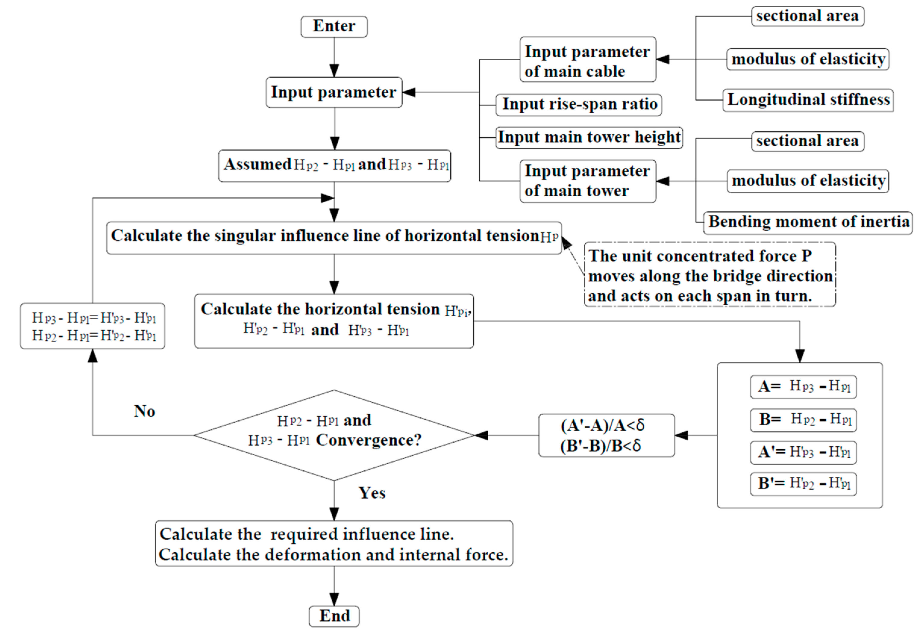
3.1. Ideas of Solving Equations

For a multi-tower self-anchored suspension bridge, the basic differential equation becomes nonlinear because the longitudinal stiffness of the main tower was considered. Taking the self-anchored suspension bridge with three towers and four spans as an example, there are two nonlinear terms ( H p 2 H p 1 ) d 2 η 2 dx 2 and ( H p 3 H p 1 ) d 2 η 3 dx 2 in the equation of the two main spans. Because the horizontal tension H p and deflection η of each span is a function of live load, it is necessary to assume the live load horizontal tension H p of each main cable before solving the differential equation. Only by ensuring that the calculated value is consistent with the assumed value can the obtained result be accurate. If the error between the calculated value and the assumed value does not meet the requirements, it is necessary to correct the assumed value and recalculate until the accuracy requirements are met.
The “beam substitution method” [19] proposed by Professor Lee is adopted. According to the derived equilibrium differential equation of the bridge, the stiffened beam can be regarded as an ordinary continuous beam which is not suspended from the main cable, as shown in Figure 2. Note that the live load p(x) in this paper includes concentrated load p and uniformly distributed load q. The uniform tension of suspension cable refers to the sling tension borne by the stiffening beam per meter, as shown in Figure 2b. For convenience of expression, let q1 = H p 1 d 2 y 1 dx 2 , q2 = H p 2 d 2 y 2 dx 2 , q3 = H p 3 d 2 y 3 dx 2 , q4 = H p 4 d 2 y 4 dx 2 .
The continuous beam bears the live load and the distribution tension of suspension cable, and the two main spans also act on the axial force Hp2-Hp1 and Hp3-Hp1. If these two axial forces are assumed to be a certain value, the Equation (9) is a linear equation, and the superposition principle is applicable at this time. Thus, the live load p(x) and the distribution force of suspension cable can be processed respectively, as shown in Figure 3.
Differential equation solving includes the following processes.
(1) Firstly, the formula for calculating the horizontal tension of each main cable under live load can be obtained from the deformation compatibility equation (Equation (17)).
(2) Secondly, replace the beam as shown in Figure 2. Based on the principle of force method in structural mechanics, the bending moment of the inner support of the four-span continuous beam is calculated respectively under the action of live load p(x) and the distribution force of suspension cable. The actual bending moment is obtained by superimposing them. Note that the bending moment obtained here is not a specific value but contains an unknown formula.
(3) Thirdly, according to the equilibrium differential equation (Equation (9)), the deflection can be calculated respectively under the action of live load and the uniform tension of the suspension cable.
(4) Fourthly, according to Formula 19, the bending moment M and shear force Q can be obtained.
M = EI d 2 η dx 2 Q = dM dx
Because of the different positions of live loads, the formulas for calculating deflection, bending moment and shearing force of stiffened beams are different. To avoid being tedious and lengthy, the deflection, bending moment and shearing force of the left side span stiffening beam are given under the uniform tension of suspension cable.
On the left span, the deflection, bending moment and shear force under the uniform tension of suspension cable are shown in Equation (20).
η = q 1 x 24 E 1 I 1 l 1 3 2 l 1 x 2 + x 3 + M 1 x 6 l 1 E 1 I 1 l 1 2 x 2 M = q 1 x l 1 x 2 + M 1 x l 1 Q = q 1 l 1 x 2 + M 1 l 1  
where: η = deflection. M = the bending moment. Q = shear force. M1 = Bending moment across the second support position on the left span. q1 = the uniform tension of suspension cable of left side span. E1A1 = the axial stiffness of each span stiffening beam. l1 = Left span length. x = longitudinal position.

3.2. Matlab Calculation Flow

If P is defined as the unit concentrated force, it moves along the direction of the bridge span and acts on each span in turn. The curve of deformation and internal force of any specified section can be obtained, which is the influence line of deformation and internal force of the specified section. However, the influence line obtained for the first time is a “singular” influence line, and its meaning is uncertain because the influence line needs to be verified. Therefore, for a given load situation, only iterative calculation is needed to obtain the corresponding Hp2-Hp1 and Hp3-Hp1. When the calculation results of Hp2-Hp1 and Hp3-Hp1 converge, the influence line is used to calculate the real internal force and deformation.
To obtain the calculation results quickly, Matlab language is used to implement the calculation. The theoretical analytical calculation considering the longitudinal stiffness of the main tower is realized, and the calculation flow is shown in Figure 4. Through the MATLAB calculation process, the approximate calculation of structural deformation and internal force under any given load can be carried out only by inputting relevant design parameters.

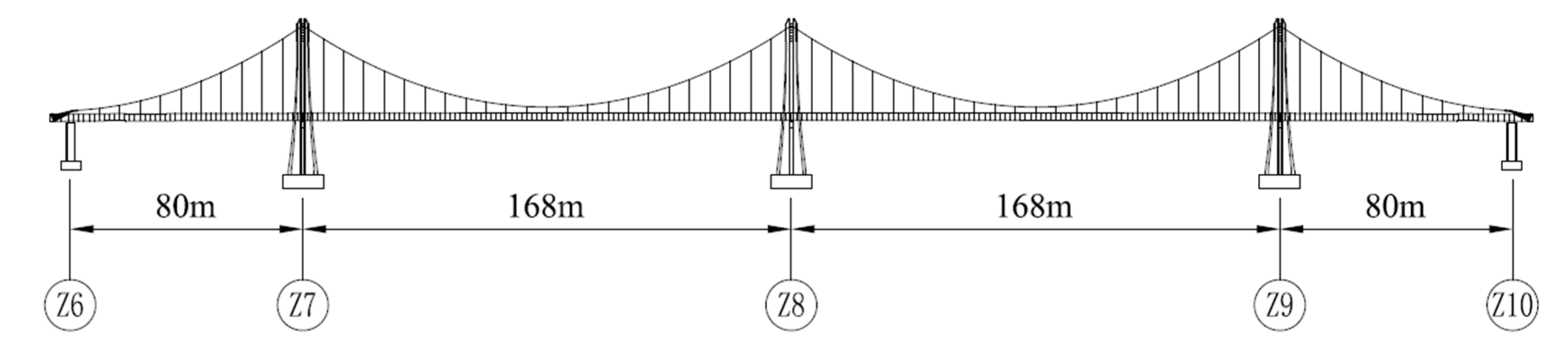
4. Application Example

The Luozhou Bridge in Fuzhou, China, is a self-anchored suspension bridge with three towers and four spans. The span layout is 80 m + 168 m + 168 m + 80 m, as shown in Figure 5. Main design parameters: the rise-span ratio of main span is 1/6, the height of the main tower is 48.9 m, the elastic modulus of stiffening beam is 2.06 × 10⁵ MPa, the elastic modulus of main cable is 1.95 × 10⁵ MPa, the longitudinal stiffness of main tower (single tower) is 50 MN/m, the vertical bending moment of stiffening beam is 1.690 m4 and the cross-sectional area of stiffening beam is 1.501 m2.

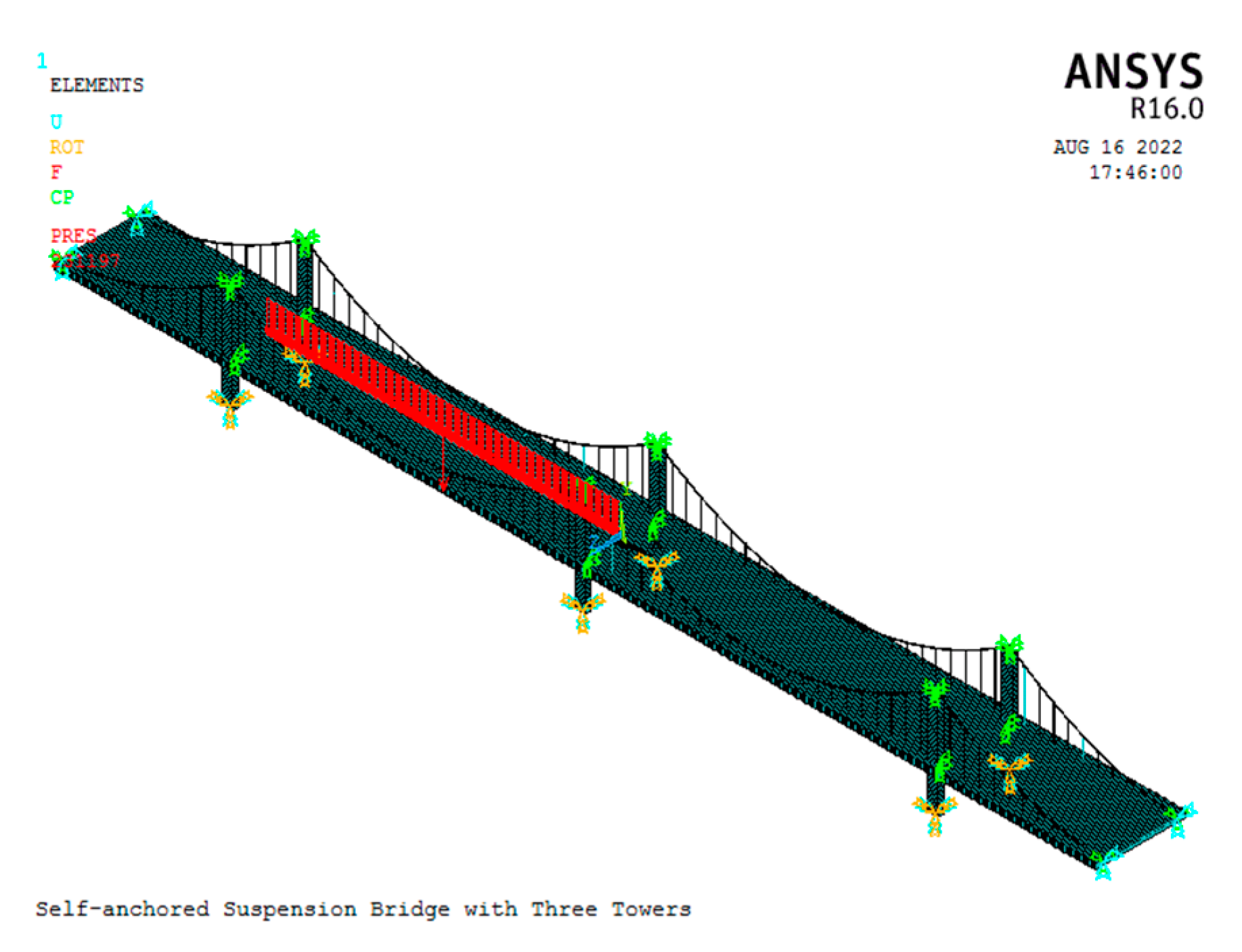
4.1. Finite Element Model

To verify the applicability of the analytical algorithm, a three-dimensional beam element model of self-anchored suspension bridge with three towers and four spans was established by ANSYS. The main tower and stiffening beam were simulated by Beam44, which has the ability to bear tension, compression, torsion and bending. In order to connect the stiffening beam with the sling, the Beam4 element was used to simulate the rigid beam, and the element is given enough rigidity to make it a rigid arm. The main cable and sling were simulated by Link10 unit, which has the functions of stress stiffening and large deformation. The finite element model did not consider the influence of pile caps, foundations and side piers. The model has a total of 1210 units and 1087 nodes. The finite element model was shown in Figure 6. The bottom of the tower was set as a fixed boundary, and the supports of the main tower and the stiffening beam were simulated by coupling the degrees of freedom of the corresponding nodes. The edge pier support was realized by restricting the node degree of freedom of the edge pier support position of the stiffening beam. For the consolidation of the main cable saddle and the main tower, it was realized by coupling the three-way displacement of the corresponding nodes X, Y and Z. The anchorage between the main cable and the stiffening beam is simulated by coupling the degrees of freedom of the corresponding nodes. The live load refers to the grade I lane load standard of highway [20]. After considering multi-lane and longitudinal and transverse reduction, the line load is 40.74 KN/m, and the concentrated load is 1396.8 KN.

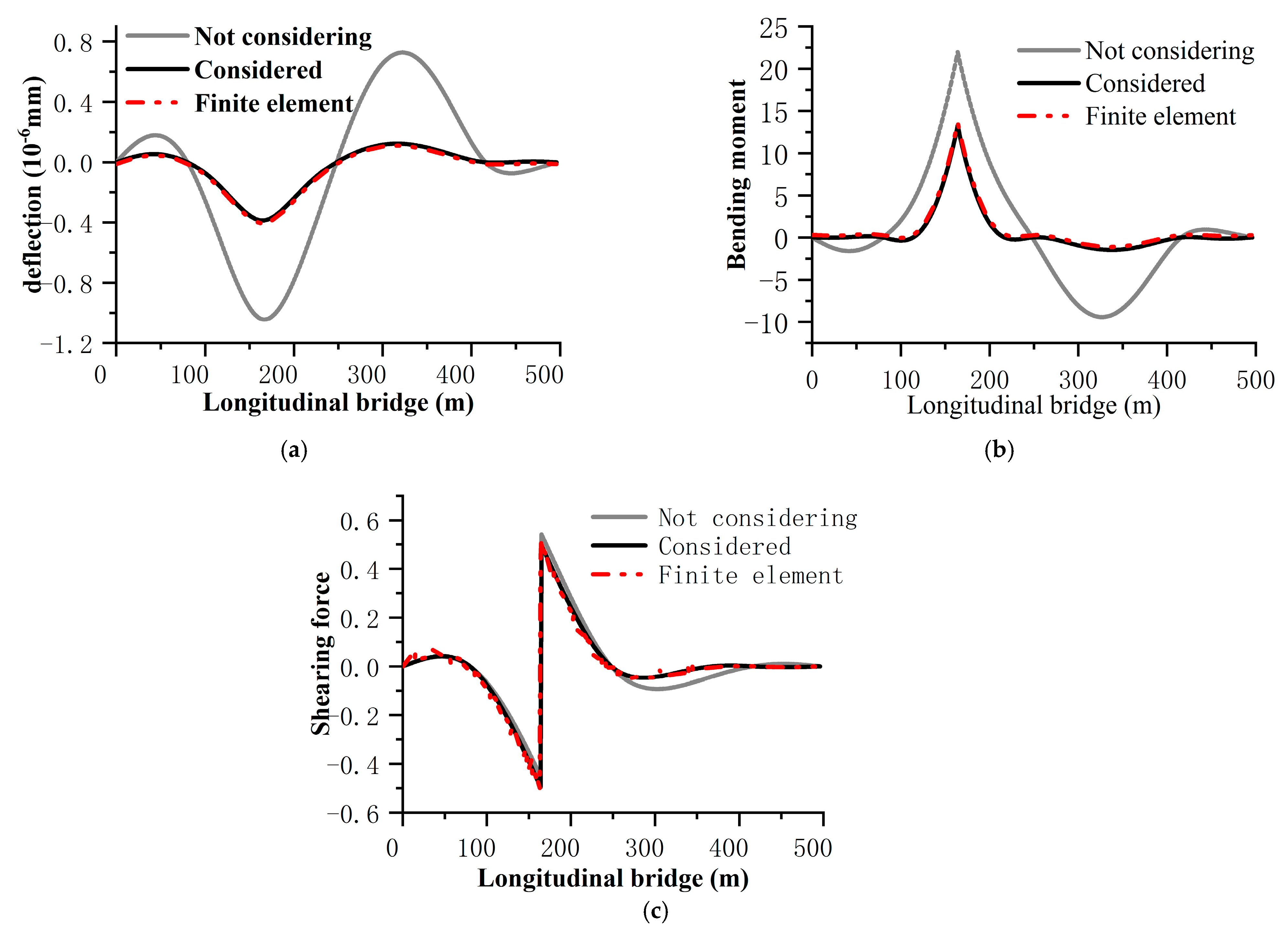
4.2. Comparison of Calculation Results

In order to further compare the influence of considering the stiffness of the main tower, a deflection theoretical calculation program without considering the stiffness of the main tower is implemented. In Figure 7, based on the deflection theory, the deflection and internal force influence lines of the middle section of the left main span of the stiffened beam are also calculated without considering the stiffness of the main tower, considering the stiffness of the main tower and ANSYS finite element calculation. As can be seen from Figure 7, the influence lines of internal force and deformation of the three are very close.
In Table 1, Table 2 and Table 3, the deflection, bending moment and shearing force of the middle section of the left main span of the stiffening beam are listed when the left main span is arranged with live load. It can be seen from Table 1 that the calculation results considering the longitudinal stiffness of the main tower are in good agreement with those obtained by nonlinear finite element method. The maximum error of deflection of the stiffening beam is within 8%. Even in the middle of the right span, the section deformation is only 1 mm error. As for the bending moment of the stiffening beam, as shown in Table 2, the calculation result considering the longitudinal stiffness of the main tower is highly consistent with that of the nonlinear finite element method, and the maximum error is within 12.5%. It can be seen that the accuracy of this calculation method completely meets the preliminary design and parameter analysis of the structure.
However, because the deflection theory regards the slings as vertically densely distributed along the whole bridge span and only provides the “membrane” of vertical resistance, without considering its elongation and inclination under live load, the calculated shear force error is large. The maximum error of shearing force has reached 36.55%. In addition, it should be pointed out that this is a method of approximate calculation.
As far as the calculation results are concerned, there is a big difference in the deflection theory whether the longitudinal stiffness of the main tower is considered or not. The shape of the influence line of internal force and deformation is also very different. There is a big difference between positive and negative influences. Thus, the deflection theory without considering the longitudinal stiffness of the main tower cannot truly reflect the internal force and deformation characteristics of the structure. Therefore, the theoretical analysis of deflection of multi-tower self-anchored suspension bridge needs to consider the influence of the longitudinal stiffness of the main tower.

5. Conclusions

In this paper, based on the deflection theory, the static analysis of multi-tower self-anchored suspension bridge is studied by analytical method, and the following conclusions are obtained.
(1)
Based on the deflection theory, for a multi-tower self-anchored suspension bridge, there is a nonlinear term in the balance differential equation established by adding the influence of the stiffness of the main tower. The nonlinearity is mainly manifested in the coupling term between the horizontal tension difference of the live load of the adjacent main cable and the corresponding deformation in the main span balance equation.
(2)
Different from the previous theoretical analysis of deflection of ground-anchored suspension bridge, the axial compression deformation of stiffening beam should be considered when establishing the deformation coordination equation of multi-tower self-anchored suspension bridge. Meanwhile, whether the longitudinal horizontal displacement of the top of the main tower is considered has great influence on the internal force and deformation of the multi-tower self-anchored suspension bridge.
(3)
The practical calculation formula of internal force and deformation of multi-tower self-anchored suspension bridge derived in this paper has a clear mechanical concept, which can theoretically explain the mechanical characteristics of the structure. In addition, it can be applied to single-tower and double-tower self-anchored suspension bridges and ground-anchored suspension bridges only by appropriately modifying the static analysis calculation formula and the MATLAB calculation program of the multi-tower self-anchored suspension bridge.

Author Contributions

Conceptualization, Y.-j.C. and J.-w.Z.; formal analysis, Y.-j.C. and S.W.; methodology, J.-w.Z.; software, Y.-j.C. and S.W.; resources, F.L. and J.-w.Z.; writing—review and editing, Y.-j.C. and S.W.; supervision, S.W. and Y.-j.C. All authors have read and agreed to the published version of the manuscript.

Funding

This research was funded by Fujian Natural Science Foundation Project and grant number [JA14039] and the APC was funded by [2016J05122].

Institutional Review Board Statement

We choose to exclude this statement because the study did not require ethical approval.

Informed Consent Statement

Informed consent was obtained from all subjects involved in the study.

Data Availability Statement

We choose to exclude this statement because the study did not report any data.

Acknowledgments

The authors acknowledge the support from Fujian Provincial Education Department.

Conflicts of Interest

The authors declare no conflict of interest.

References

  1. Latimer, M.; Hindle, B.; Kranzberg, M. Bridge to the Future: A Centennial Celebration of the Brooklyn Bridge-introduction. Ann. N. Y. Acad. Sci. 1984, 424, 9–12. [Google Scholar]
  2. Ochsendorf, J.A.; Billington, D.P. Self-anchored suspension bridges. J. Bridge Eng. 1999, 4, 151–156. [Google Scholar] [CrossRef]
  3. Kim, H.-K.; Lee, M.-J.; Chang, S.-P. Non-linear shape-finding analysis of a self-anchored suspension bridge. Eng. Struct. 2002, 24, 1547–1559. [Google Scholar] [CrossRef]
  4. Gil, H.; Choi, Y. Cable Erection Test at Splay Band for Spatial Suspension Bridge. J. Bridge Eng. 2002, 7, 300–307. [Google Scholar] [CrossRef]
  5. Sun, J.; Manzanarez, R.; Nader, M. Design of Looping Cable Anchorage System for New San Francisco-Oakland Bay Bridge Main Suspension Span. J. Bridge Eng. 2002, 7, 315–324. [Google Scholar] [CrossRef]
  6. Xu, F.; Zhang, M.; Wang, L.; Zhang, Z. Self-Anchored suspension bridges in China. Pract. Period. Struct. Des. Constr. 2017, 22, 1–10. [Google Scholar] [CrossRef]
  7. Tao Song, T.; Wang, B.; Song, Y. A Simplified Calculation Method for Multi-Tower Self-Anchored Suspension Bridges Based on Frame Structure Theory Model. Int. J. Steel Struct. 2022, 22, 373–388. [Google Scholar] [CrossRef]
  8. Chang, F.; Chen, L.; Shao, C.; Lu, D. Design of Main Bridge of Fenghuang Yellow River Bridge in Jinan. Bridge Constr. 2021, 51, 101–107. (In Chinese) [Google Scholar]
  9. Lei, S.; Liu, C.; Zhang, Z. Basic differential equation deductive of the self-anchored suspension bridge. J. Harbin Inst. Technol. 2004, 36, 1733–1735. (In Chinese) [Google Scholar]
  10. Shen, R.; Wang, Z. Study on mechanical property of self-anchored suspension bridge based upon deflection theory. J. Highw. Transp. Res. Dev. 2008, 25, 94–98. (In Chinese) [Google Scholar]
  11. Tang, M. The Static and Dynamic Performance Study of Long-Span Self-Anchored Suspension Bridges and Parameter Sensitivity Analysis. Ph.D. Thesis, Central South University, Changsha, China, March 2007. [Google Scholar]
  12. Huang, Q.; Ye, M. Study on Simplified Calculation Method of Self-anchored Suspension Bridge. J. China Railw. Soc. 2008, 30, 122–126. (In Chinese) [Google Scholar]
  13. Zhang, W.; Yang, C.; Wang, Z.; Liu, Z. An analytical algorithm for reasonable central tower stiffness in the three-tower suspension bridge with unequal-length main spans. Eng. Struct. 2019, 199, 109595. [Google Scholar] [CrossRef]
  14. Sun, Y.; Zhu, H.-P.; Xu, D. New Method for Shape Finding of Self-Anchored Suspension Bridges with Three Dimensionally Curved Cables. J. Bridge Eng. 2015, 20, 1–22. [Google Scholar] [CrossRef]
  15. Buonopane, S.G.; Billington, D.P. Theory and history of suspension bridge design from 1823 to 1940. J. Struct. Eng. (United States) 1993, 119, 954–977. [Google Scholar] [CrossRef]
  16. Jung, M.-R.; Shin, S.-U.; Attard, M.M.; Kim, M.-Y. The flection Theory for Self-Anchored Suspension Bridges under Live Load. J. Bridge Eng. 2015, 20, 1–19. [Google Scholar] [CrossRef]
  17. Zhang, Z. Self-Anchored Concrete Suspension Bridge; People’s Communications Publishing House: Beijing, China, 2005. [Google Scholar]
  18. Pang, H.; Wang, J.; Li, X. Static analysis of suspension bridges based on deflection theory. J. Hefei Univ. Technol. Nat. Sci. Ed. 2010, 33, 261–265. (In Chinese) [Google Scholar]
  19. Lee, B. Research on Bridge and Structure Theory; Shanghai Science and Technology Literature Publishing House: Shanghai, China, 1983; pp. 1–12. [Google Scholar]
  20. Professional Standard of the People’s Republic of China, JTG T60-2015; General Code for Design of Highway Bridges and Culverts. Communications Press: Beijing, China, 2015.
Figure 1. Schematic diagram of three-tower self-anchored suspension bridge.
Applsci 12 08499 g001
Figure 2. Substitutional beam under live load. q1, q2, q3 and q4 = the uniform tension of suspension cable.
Applsci 12 08499 g002
Figure 3. Load superposition calculation. q1, q2, q3 and q4 = the uniform tension of suspension cable of each span.
Applsci 12 08499 g003
Figure 4. MATLAB calculation flow chart.
Applsci 12 08499 g004
Figure 5. Layout of the Luozhou Bridge.
Applsci 12 08499 g005
Figure 6. Finite element model of the Luozhou Bridge.
Applsci 12 08499 g006
Figure 7. Internal force and deformation influence line of middle section of left main span. (a) Deflection influence line. (b) Bending moment influence line. (c) Shear influence line.
Applsci 12 08499 g007
Table 1. The deformation of control section of stiffening beam under live load in the middle section of left main span.
Section PositionFinite Element Results (m)Without Considering the Stiffness of the Main Tower Considering Stiffness of Main Tower
Computed Value (m)ErrorComputed Value (m)Error
Mid-span section of the left span0.0380.05750.00%0.035−7.89%
Mid-span section of the left main span−0.194−0.36186.08%−0.189−2.58%
Mid-span section of the right main span0.0650.10460.00%0.0707.69%
Mid-span section of the right span0.0070.019−23.59%0.006−14.29%
Table 2. The bending moment of control section of stiffening beam under live load in the middle section of left main span.
Section PositionFinite Element Results (KN·m)Without Considering the Stiffness of the Main TowerConsidering Stiffness of Main Tower
Computed Value (KN·m)ErrorComputed Value (KN·m)Error
Mid-span of the left span−17,955−29,39463.71%−16,567−7.73%
Support of left tower−20,472−35,89975.36%−19,381−5.33%
Mid-span of the left main span38,13156,83249.04%36,987−3.00%
Support of middle tower−16,920−20,18219.28%−14,820−12.41%
Mid-span of the right main span−7051−11,98069.90%−77119.36%
Support of right tower 10,70821,26998.63%11,534−7.71%
Mid-span of the right span−1630−231942.27%−180910.98%
Table 3. The shearing force of control section of stiffening beam under live load in the middle section of left main span.
Section PositionFinite Element Results (KN)Without Considering the Stiffness of the Main TowerConsidering Stiffness of Main Tower
Computed Value (KN)ErrorComputed Value (KN)Error
Support of left tower8522−74.12%11636.47%
Mid-span of the left main span585447−23.59%69236.47%
Support of middle tower850132255.53%588−30.82%
Support of right tower38358853.52%52336.55%
Publisher’s Note: MDPI stays neutral with regard to jurisdictional claims in published maps and institutional affiliations.

