
Experimental and Numerical Investigations of the Vibration and Acoustic Properties of Corrugated Sandwich Composite Panels

Abstract
:Featured Application
Abstract
1. Introduction
2. The Fabrication of the Corrugated Sandwich Panel
2.1. Materials
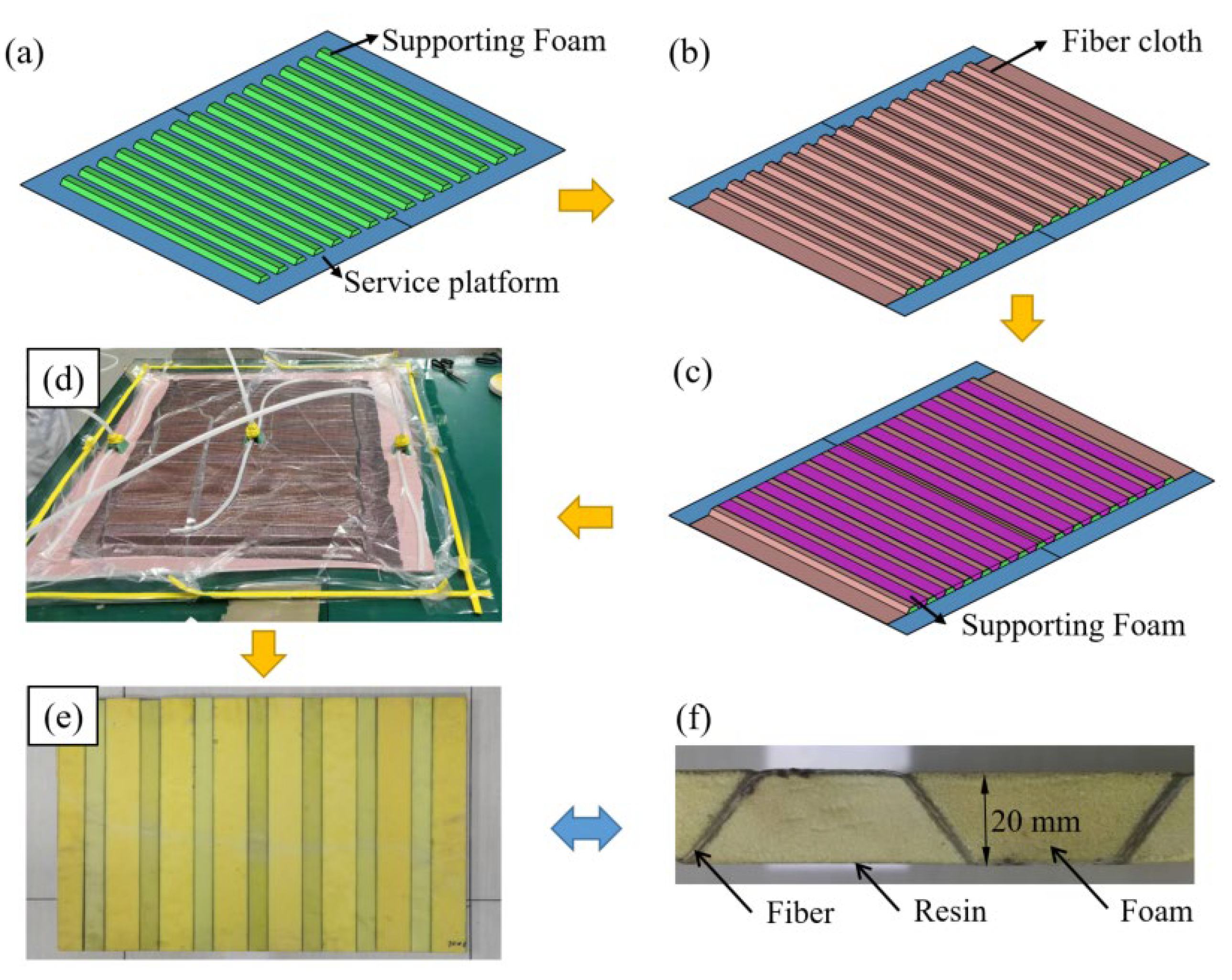
2.2. Panel Fabrication
3. Test Procedures
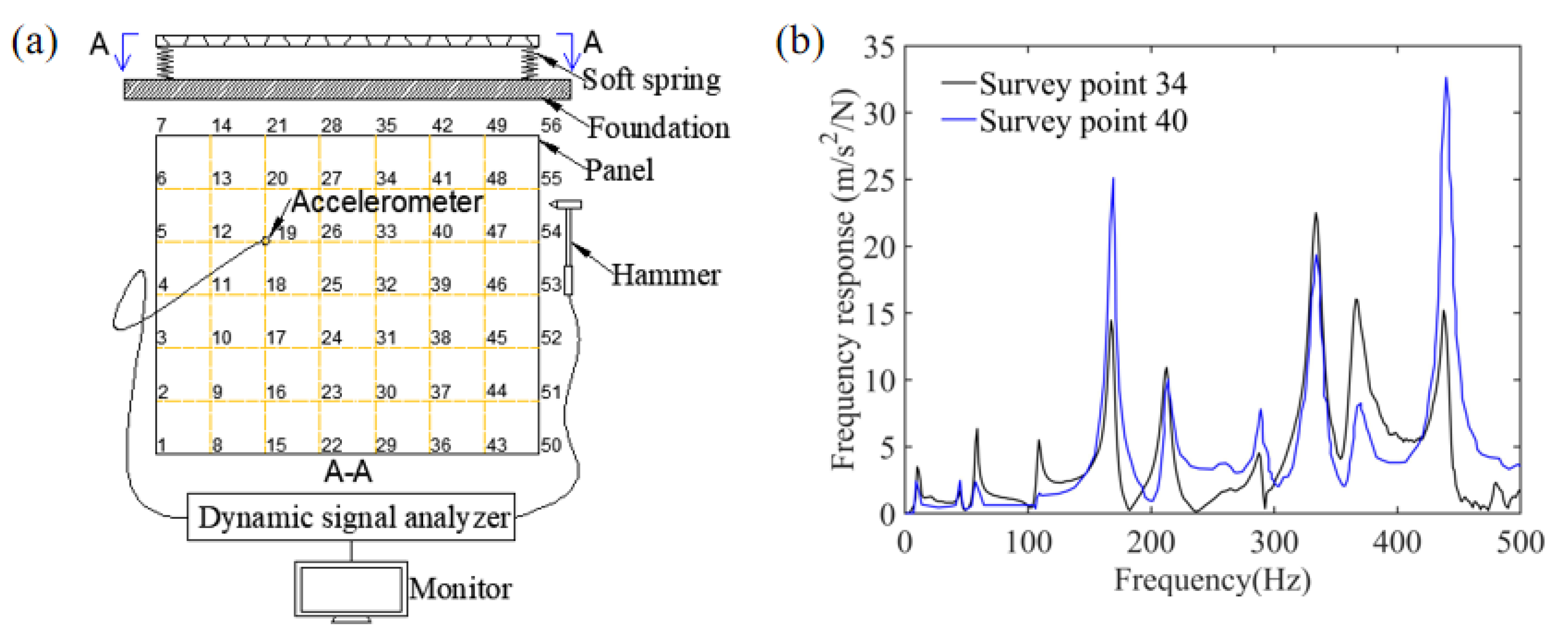
3.1. Mode Tests
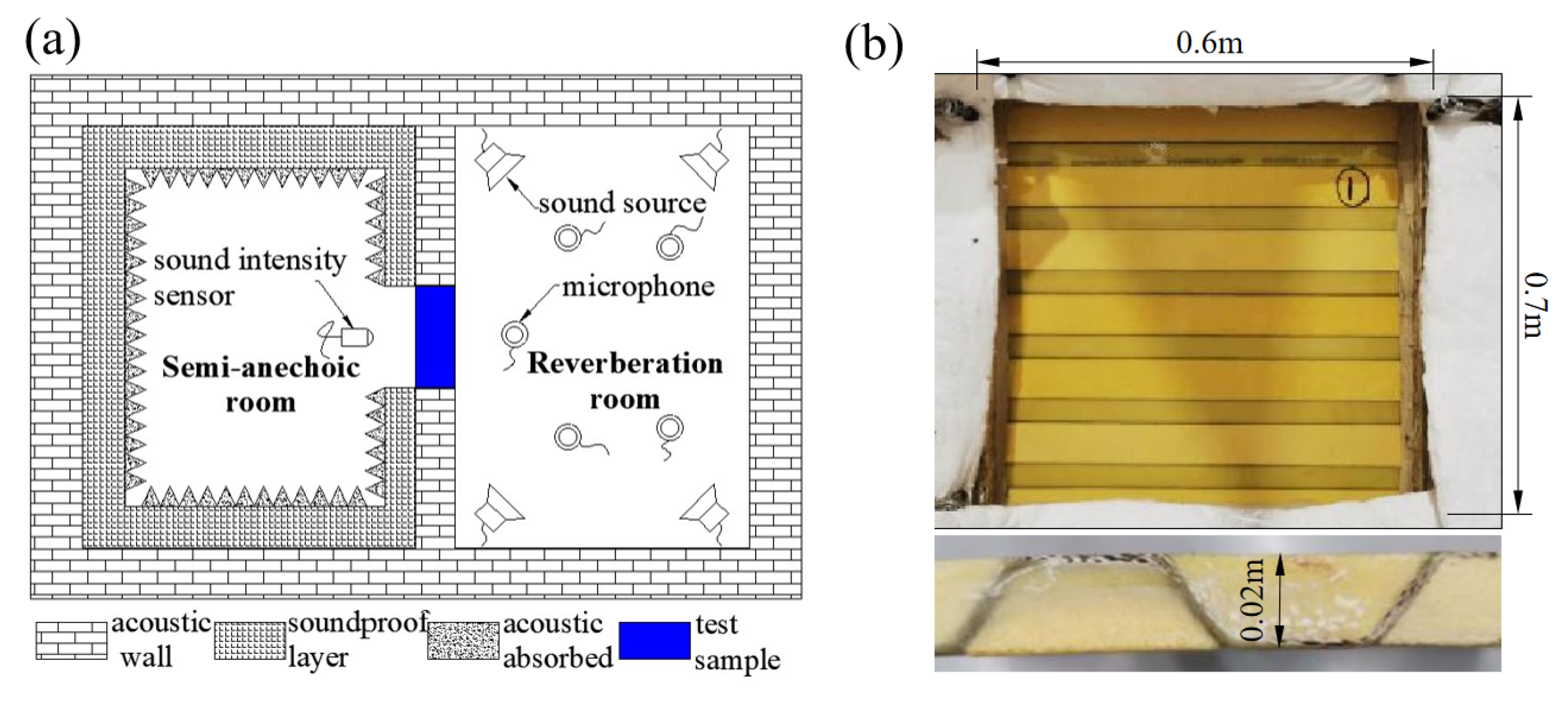
3.2. Acoustic Tests
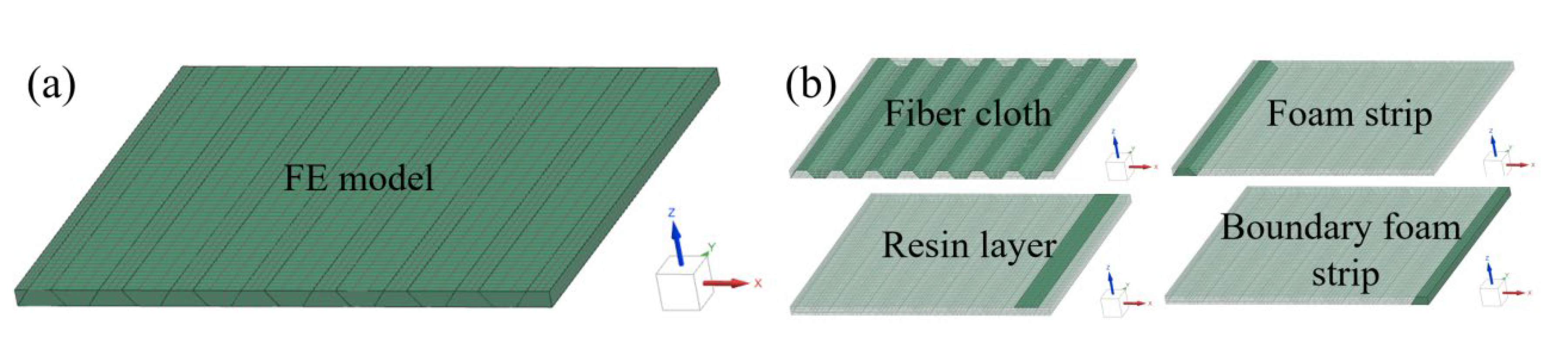
4. Numerical Simulation
4.1. Mode Analysis
4.2. Sound Transmission Level Analysis
5. Results and Discussion
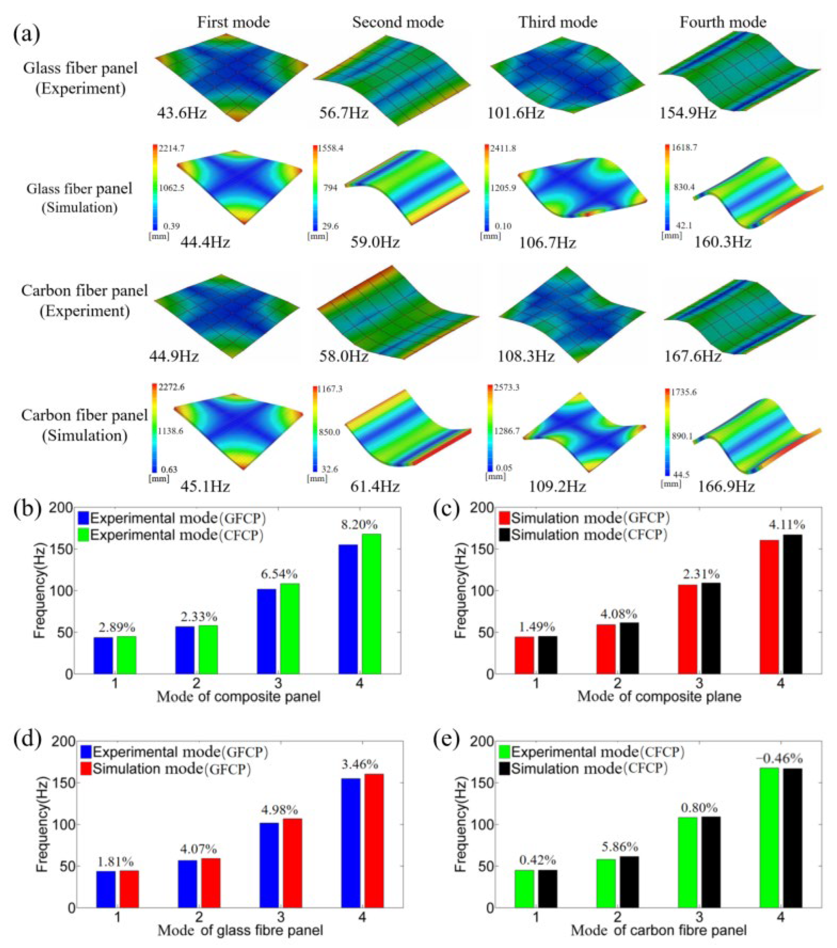
5.1. Mode Analysis
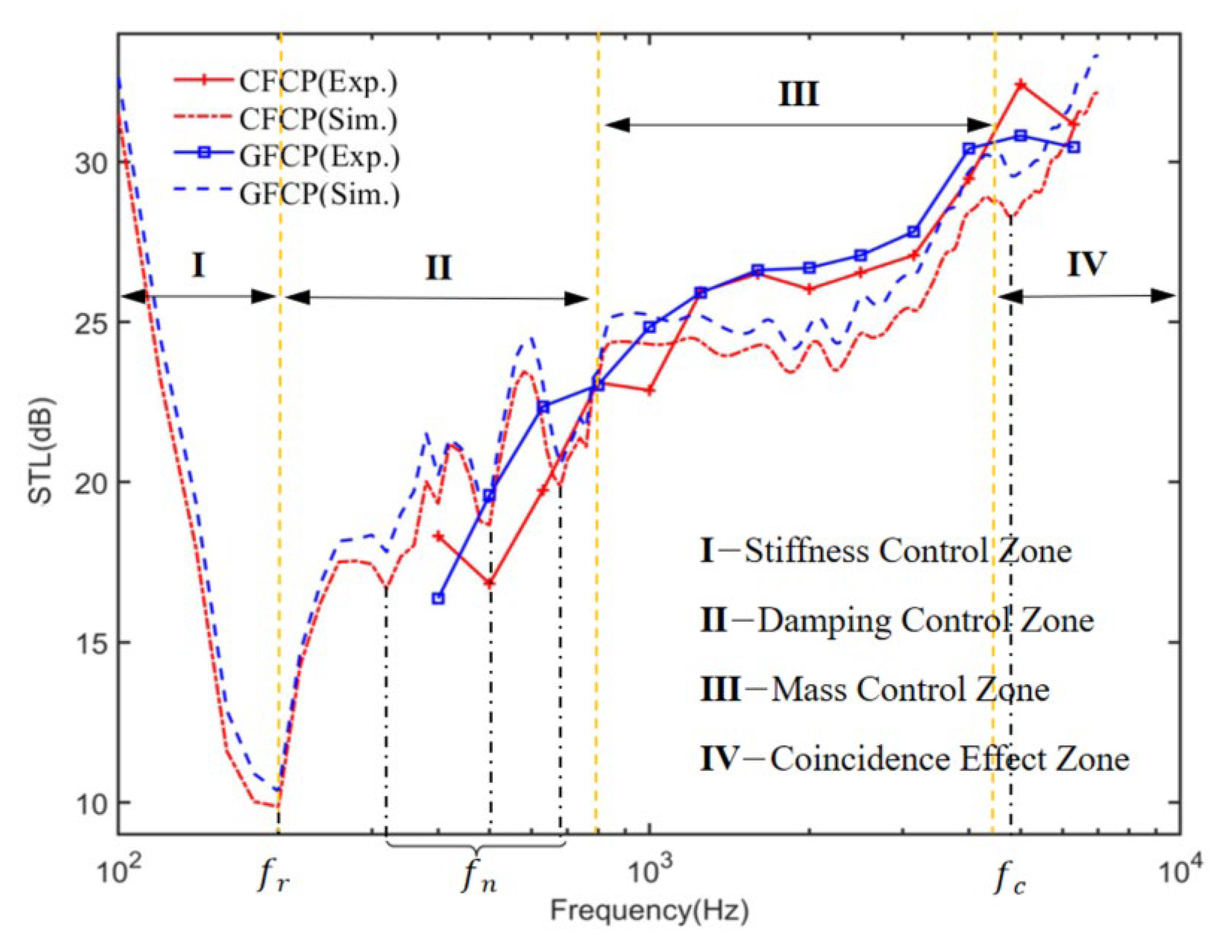
5.2. Sound Transmission Analysis
5.3. Parametric Analysis
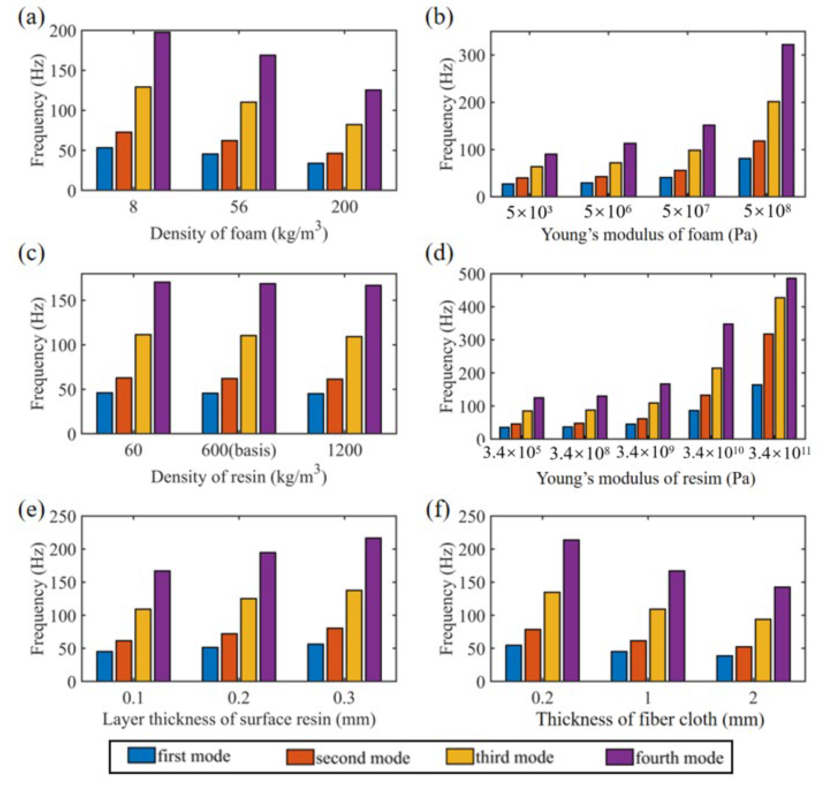
5.3.1. Parametric Analysis of Vibration Properties
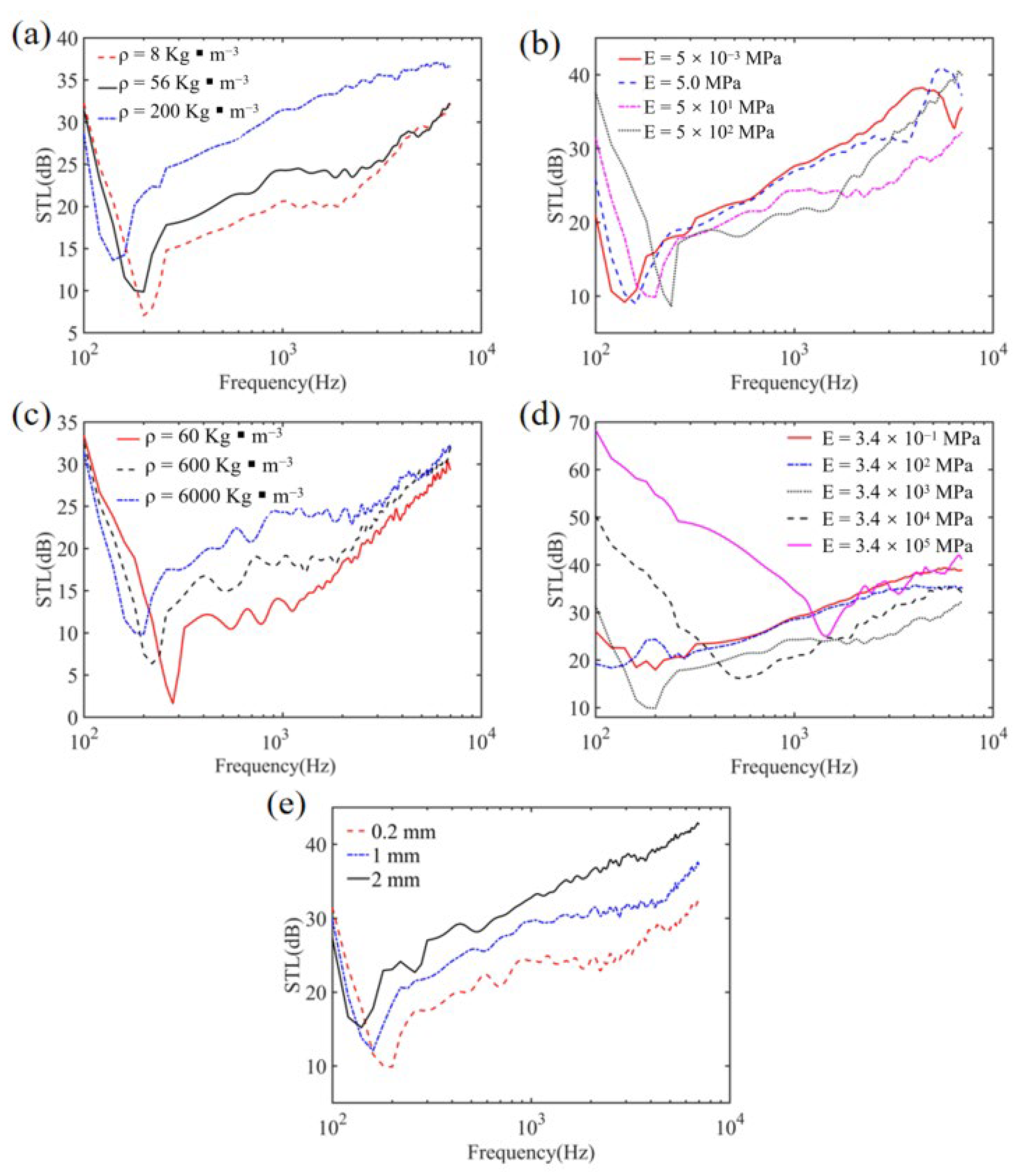
5.3.2. Parametric Analysis of Acoustic Properties
6. Conclusions
- (1)
- Low-order mode frequencies were greatly influenced by the resin layer on the panel surface, despite the extremely low thickness.
- (2)
- The density of fiber was the main factor affecting low-order modes of composite sandwiched panels. In contrast, the effect of the fiber modulus on the low-order modes was slight.
- (3)
- The layer thickness of the surface resin was the most predominant factor affecting the initial frequency of the panel’s resonant sound transmission.
- (4)
- The sound transmission loss (STL) of the sandwiched panel mainly followed the mass law. Increasing the fiber volume fraction or the fiber density can significantly increase the STL property of the corrugated panels. However, this is achieved at the cost of a decrease of the resonance frequency. Fortunately, this can be compensated by increasing the layer thickness of the surface resin. Increasing the foam density also improves the STL, while this tends to significantly increase the weight of the entire panels.
Author Contributions
Funding
Institutional Review Board Statement
Informed Consent Statement
Acknowledgments
Conflicts of Interest
References
- Zhang, Q.; Yang, X.; Li, P.; Huang, G.; Feng, S.; Shen, C.; Han, B.; Zhang, X.; Jin, F.; Xu, F.; et al. Bio-Inspired Engineering of Honeycomb Structure-Using Nature to Inspire Human Inno-vation. Prog. Mater. Sci. 2015, 74, 332–400. [Google Scholar] [CrossRef]
- Wadley, H.N.G. Multifunctional periodic cellular metals. Philos. Trans. R. Soc. A 2005, 364, 31–68. [Google Scholar] [CrossRef] [PubMed]
- Côté, F.; Deshpande, V.; Fleck, N.; Evans, A. The compressive and shear responses of corrugated and diamond lattice materials. Int. J. Solids Struct. 2006, 43, 6220–6242. [Google Scholar] [CrossRef]
- Xiong, J.; Mines, R.; Ghosh, R.; Vaziri, A.; Ma, L.; Ohrndorf, A.; Christ, H.-J.; Wu, L. Advanced Micro-Lattice Materials. Adv. Eng. Mater. 2015, 17, 1253–1264. [Google Scholar] [CrossRef]
- Xu, S.; Beynon, J.; Ruan, D.; Lu, G. Experimental study of the out-of-plane dynamic compression of hexagonal honeycombs. Compos. Struct. 2012, 94, 2326–2336. [Google Scholar] [CrossRef]
- Bai, X.; Zheng, Z.; Nakayama, A. Heat transfer performance analysis on lattice core sandwich panel structures. Int. J. Heat Mass Transf. 2019, 143, 118525. [Google Scholar] [CrossRef]
- Solyaev, Y.; Lurie, S.; Koshurina, A.; Dobryanskiy, V.; Kachanov, M. On a combined thermal/mechanical performance of a foam-filled sandwich panels. Int. J. Eng. Sci. 2018, 134, 66–76. [Google Scholar] [CrossRef]
- Qin, Q.; Zhang, W.; Liu, S.; Li, J.; Zhang, J.; Poh, L. On dynamic response of corrugated sandwich beams with metal foam-filled folded plate core subjected to low-velocity impact. Compos. Part A Appl. Sci. Manuf. 2018, 114, 107–116. [Google Scholar] [CrossRef]
- Vignjevic, R.; Campbell, J.; Hughes, K.; Orłowski, M.; Garcea, S.; Withers, P.; Reed, J. Soft body impact resistance of composite foam core sandwich panels with uni-directional corrugated and tubular reinforcements. Int. J. Impact Eng. 2019, 132. [Google Scholar] [CrossRef]
- Yu, R.-P.; Wang, X.; Zhang, Q.-C.; Li, L.; He, S.-Y.; Han, B.; Ni, C.-Y.; Zhao, Z.-Y.; Lu, T.J. Effects of sand filling on the dynamic response of corrugated core sandwich beams under foam projectile impact. Compos. Part B Eng. 2020, 197, 108135. [Google Scholar] [CrossRef]
- Taghizadeh, S.; Farrokhabadi, A.; Liaghat, G.; Pedram, E.; Malekinejad, H.; Mohammadi, S.F.; Ahmadi, H. Characterization of compressive behavior of PVC foam infilled composite sandwich panels with different corrugated core shapes. Thin-Walled Struct. 2018, 135, 160–172. [Google Scholar] [CrossRef]
- Sayahlatifi, S.; Rahimi, G.H.; Bokaei, A. The quasi-static behavior of hybrid corrugated composite/balsa core sandwich struc-tures in four-point bending: Experimental study and numerical simulation. Eng. Struct. 2020, 210, 110361. [Google Scholar] [CrossRef]
- Gupta, A.; Panda, S.; Reddy, R.S. Improved damping in sandwich beams through the inclusion of dispersed graphite particles within the viscoelastic core. Compos. Struct. 2020, 247, 112424. [Google Scholar] [CrossRef]
- Xiong, J.; Ma, L.; Wu, L.; Wang, B.; Vaziri, A. Fabrication and crushing behavior of low density carbon fibre composite pyramidal truss structures. Compos. Struct. 2010, 92, 2695–2702. [Google Scholar] [CrossRef]
- PeterNilsson, M.A.; Seyed, R.A. Transverse shear stiffness of corrugated core steel sandwich panels with dual weld lines. Thin-Walled Struct. 2017, 117, 98–112. [Google Scholar]
- Kazemahvazi, S.; Zenkert, D. Corrugated all-composite sandwich structures. Part 1: Modeling. Compos. Sci. Technol. 2009, 69, 913–919. [Google Scholar] [CrossRef]
- Kazemahvazi, S.; Tanner, D.; Zenkert, D. Corrugated all-composite sandwich structures. Part 2: Failure mechanisms and experimental programme. Compos. Sci. Technol. 2009, 69, 920–925. [Google Scholar] [CrossRef]
- Fan, H.; Fang, D.; Chen, L.; Dai, Z.; Yang, W. Manufacturing and testing of a CFRC sandwich cylinder with Kagome cores. Compos. Sci. Technol. 2009, 69, 2695–2700. [Google Scholar] [CrossRef]
- Liu, J.; Kan, T.; Lou, J.; Xiang, L.; Zhu, X.; Tang, Y. Localized damage response of carbon fibre reinforced polymer composite sandwich panel after thermal exposure. Polym. Test 2016, 50, 33–40. [Google Scholar] [CrossRef]
- Hao, W.; Liu, Y.; Zhou, H.; Chen, H.; Fang, D. Preparation and characterization of 3D printed continuous carbon fibre reinforced thermo-setting composites. Polym. Test 2018, 65, 29–34. [Google Scholar] [CrossRef]
- Peng, L.-X.; Yan, S.-T.; Mo, G.-K.; Zhang, X. Free vibration analysis of corrugated-core sandwich plates using a meshfree Galerkin method based on the first-order shear deformation theory. Int. J. Mech. Sci. 2014, 78, 8–18. [Google Scholar] [CrossRef]
- Wang, Y.-J.; Zhang, Z.-J.; Xue, X.-M.; Zhang, L. Free vibration analysis of composite sandwich panels with hierarchical honeycomb sandwich core. Thin-Walled Struct. 2019, 145, 106425. [Google Scholar] [CrossRef]
- Wang, X.; Zhao, Z.Y.; Li, L.; Zhang, Z.J.; Zhang, Q.C.; Han, B.; Lu, T.J. Free vibration behavior of Ti-6Al-4V sandwich beams with corrugated channel cores: Ex-periments and simulations. Thin Wall Struct. 2019, 135, 329–340. [Google Scholar] [CrossRef]
- Xu, G.-D.; Zeng, T.; Cheng, S.; Wang, X.-H.; Zhang, K. Free vibration of composite sandwich beam with graded corrugated lattice core. Compos. Struct. 2019, 229, 111466. [Google Scholar] [CrossRef]
- Magnucka-Blandzi, E.; Walczak, Z.; Wittenbeck, L.; Jasion, P.; Rodak, M.; Szyc, W.; Lewiński, J. Stability and vibrations of a metal seven-layer rectangular plate with trapezoidal corrugated cores. Thin-Walled Struct. 2017, 114, 154–163. [Google Scholar] [CrossRef]
- Guo, J.; Xiao, Y.; Zhang, S.; Wen, J. Bloch wave based method for dynamic homogenization and vibration analysis of lattice truss core sandwich structures. Compos. Struct. 2019, 229, 111437. [Google Scholar] [CrossRef]
- Yang, J.-S.; Liu, Z.-D.; Schmidt, R.; Schröder, K.-U.; Ma, L.; Wu, L.-Z. Vibration-based damage diagnosis of composite sandwich panels with bi-directional corrugated lattice cores. Compos. Part A Appl. Sci. Manuf. 2020, 131, 105781. [Google Scholar] [CrossRef]
- Han, B.; Qin, K.-K.; Zhang, Q.-C.; Zhang, Q.; Lu, T.J.; Lu, B.-H. Free vibration and buckling of foam-filled composite corrugated sandwich plates under thermal loading. Compos. Struct. 2017, 172, 173–189. [Google Scholar] [CrossRef]
- Arunkumar, M.; Bhagat, V.; Geng, Q.; Li, Y.; Pitchaimani, J. An exact solution for vibro-acoustic response of smart sandwich panels with MEE composite Layer. Compos. Struct. 2022, 286, 115201. [Google Scholar] [CrossRef]
- Mohammadi, H.; Setoodeh, A.; Vassilopoulos, A. Isogeometric Kirchhoff–Love shell patches in free and forced vibration of sinusoidally corrugated FG carbon nanotube-reinforced composite panels. Thin-Walled Struct. 2022, 171, 108707. [Google Scholar] [CrossRef]
- Scislo, L.; Guinchard, M. Non-invasive measurements of ultra-lightweight composite materials using Laser Doppler Vi-brometry system. In Proceedings of the 26th International Congress on Sound and Vibration, Montréal, Canada, 7–11 July 2019. [Google Scholar]
- Scislo, L. Quality Assurance and Control of Steel Blade Production Using Full Non-Contact Frequency Response Analysis and 3D Laser Doppler Scanning Vibrometry System. In Proceedings of the 2021 11th IEEE International Conference on Intelligent Data Acquisition and Advanced Computing Systems: Technology and Applications (IDAACS), Cracow, Poland, 22–25 September 2021; pp. 419–423. [Google Scholar] [CrossRef]
- Di Lorenzo, E.; Mastrodicasa, D.; Wittevrongel, L.; Lava, P.; Peeters, B. Full-field modal analysis by using digital image correlation technique, Rotating Machinery. Opt. Methods Scanning LDV Methods 2020, 6, 119–130. [Google Scholar]
- Shen, C.; Xin, F.; Lu, T. Theoretical model for sound transmission through finite sandwich structures with corrugated core. Int. J. Non-Linear Mech. 2012, 47, 1066–1072. [Google Scholar] [CrossRef]
- Fu, T.; Chen, Z.; Yu, H.; Wang, Z.; Liu, X. An analytical study of sound transmission through corrugated core FGM sandwich plates filled with porous material. Compos. Part B Eng. 2018, 151, 161–172. [Google Scholar] [CrossRef]
- Bartolozzi, G.; Pierini, M.; Orrenius, U.; Baldanzini, N. An equivalent material formulation for sinusoidal corrugated cores of structural sandwich panels. Compos. Struct. 2013, 100, 173–185. [Google Scholar] [CrossRef]
- Tang, Y.; He, W.; Xin, F.; Lu, T.J. Nonlinear sound absorption of ultralight hybrid-cored sandwich panels. Mech. Syst. Signal Process. 2019, 135, 106428. [Google Scholar] [CrossRef]
- Wang, D.-W.; Wen, Z.-H.; Glorieux, C.; Ma, L. Sound absorption of face-centered cubic sandwich structure with micro-perforations. Mater. Des. 2019, 186, 108344. [Google Scholar] [CrossRef]
- Shahsavari, H.; Kornokar, M.; Talebitooti, R.; Daneshjou, K. The study of sound transmission through sandwich cylindrical shells with circumferentially corrugated cores filled with porous materials. Compos. Struct. 2022, 291, 115608. [Google Scholar] [CrossRef]
- Jin, Y.; Yang, Y.; Wen, Z.; He, L.; Cang, Y.; Yang, B.; Djafari-Rouhani, B.; Li, Y.; Li, Y. Lightweight sound-absorbing metastructures with perforated fish-belly panels. Int. J. Mech. Sci. 2022, 226, 107396. [Google Scholar] [CrossRef]
- Luo, Z.; Li, T.; Yan, Y.; Zhou, Z.; Zha, G. Prediction of sound insulation performance of aramid honeycomb sandwich panel based on arti-ficial neural network. Appl. Acous. 2022, 190, 108656. [Google Scholar] [CrossRef]
- Zhao, T.; Jiang, Y.; Zhu, Y.; Wan, Z.; Xiao, D.; Li, Y.; Li, H.; Wu, C.; Fang, D. An experimental investigation on low-velocity impact response of a novel corrugated sandwiched composite structure. Compos. Struct. 2020, 252, 112676. [Google Scholar] [CrossRef]
- Wang, X.; Li, X.; Yu, R.-P.; Ren, J.-W.; Zhang, Q.-C.; Zhao, Z.-Y.; Ni, C.-Y.; Han, B.; Lu, T.J. Enhanced vibration and damping characteristics of novel corrugated sandwich panels with polyurea-metal laminate face sheets. Compos. Struct. 2020, 251, 112591. [Google Scholar] [CrossRef]
- Guillaume, P.; Verboven, P.; Vanlanduit, S.; Auweraer, H.V.D.; Peeters, B. A poly-reference implementation of the least-squares complex frequency-domain estimator. Proceedings of IMAC: A Conference & Exposition on Structural Dynamics, Society for Experimental Mechanics, Kissimmee, FL, USA, 3–6 February 2003. [Google Scholar]
- Crocker, M.J.; Raju, P.K.; Forssen, B. Measurement of Transmission Loss of Panels by the Direct Determination of Transmitted Acoustic Intensity. Noise Control Eng. 1981, 17, 6. [Google Scholar] [CrossRef]
- Cops, A.; Minten, M. Comparative Study Between the Sound Intensity Method and the Conventional Two-Room Method to Calculate the Sound Transmission Loss of Wall Construction. Noise Control Eng. J. 1984, 22, 104. [Google Scholar] [CrossRef]
- Bies, D.A.; Hansen, C.; Howard, C. Engineering Noise Control, 5th ed.; CRC Press: Boca Raton, FL, USA, 2017. [Google Scholar]
- Ji, H.; Han, B.; Cheng, L.; Inman, D.J.; Qiu, J. Frequency attenuation band with low vibration transmission in a finite-size plate strip embedded with 2D acoustic black holes. Mech. Syst. Signal Process. 2021, 163, 108149. [Google Scholar] [CrossRef]
- Gibson, R.F. Principles of Composite Material Mechanics, 4th ed.; CRC Press: Boca Raton, FL, USA, 2016. [Google Scholar]

| Material Properties of CFC | ||||||
| Parameter | E11 (GPa) | E22 (GPa) | µ12 | E33 (GPa) | µ23 | µ13 |
| Value | 60.0 | 60.0 | 0.042 | 6.7 | 0.25 | 0.25 |
| Parameter | G12 (GPa) | G23 (GPa) | G13 (GPa) | α11 | α22 | α33 |
| Value | 3.7 | 3.5 | 3.5 | 1.7 × 10⁻⁶ | 1.7 × 10⁻⁶ | 7.9 × 10⁻⁶ |
| Material Properties of GFC | ||||||
| Parameter | E11 (GPa) | E22 (GPa) | µ12 | E33 (GPa) | µ23 | µ13 |
| Value | 22.0 | 22.0 | 0.3 | 9.0 | 0.45 | 0.3 |
| Parameter | G12 (GPa) | G23 (GPa) | G13 (GPa) | α11 | α22 | α33 |
| Value | 4.0 | 8.0 | 4.0 | 1.7 × 10⁻⁶ | 1.7 × 10⁻⁶ | 7.9 × 10⁻⁶ |
| Density (kg/m3) | Young’s Modulus (MPa) | Poisson’s Ratio | |
|---|---|---|---|
| PVC foam | 56 | 75 | 0.3 |
| Epoxy resin | 1200 | 3400 | 0.3 |
| Component | Density (kg/m3) | E—Young’s Modulus (MPa) |
|---|---|---|
| Foam | 8, 56 (basis), 200 | 5 × 10⁻³, 5, 50 (basis), 500 |
| Resin | 60, 600, 1200 (basis) | 3.4 × 10⁻¹, 3.4 × 10², 3.4 × 10³ (basis), 3.4 × 10⁴, 3.4 × 10⁵ |
| The thickness of the carbon fiber cloth (mm) | ||
| Fiber cloth | 0.2, 1 (basis), 2 | |
Publisher’s Note: MDPI stays neutral with regard to jurisdictional claims in published maps and institutional affiliations. |
© 2022 by the authors. Licensee MDPI, Basel, Switzerland. This article is an open access article distributed under the terms and conditions of the Creative Commons Attribution (CC BY) license (https://creativecommons.org/licenses/by/4.0/).
Share and Cite
Wan, Z.; Liu, Y.; Chen, X.; Wu, H.; Yin, F.; Gao, R.; Li, Y.; Zhao, T. Experimental and Numerical Investigations of the Vibration and Acoustic Properties of Corrugated Sandwich Composite Panels. Appl. Sci. 2022, 12, 8553. https://doi.org/10.3390/app12178553
Wan Z, Liu Y, Chen X, Wu H, Yin F, Gao R, Li Y, Zhao T. Experimental and Numerical Investigations of the Vibration and Acoustic Properties of Corrugated Sandwich Composite Panels. Applied Sciences. 2022; 12(17):8553. https://doi.org/10.3390/app12178553
Chicago/Turabian StyleWan, Zhishuai, Yaoguang Liu, Xinyu Chen, Hantai Wu, Fang Yin, Ruxin Gao, Ying Li, and Tian Zhao. 2022. "Experimental and Numerical Investigations of the Vibration and Acoustic Properties of Corrugated Sandwich Composite Panels" Applied Sciences 12, no. 17: 8553. https://doi.org/10.3390/app12178553