Article

Design of a 120 W Electromagnetic Shock Absorber for Motorcycle Applications

1
Energy and Power Conversion Engineering, University of Science and Technology, Daejeon 34113, Korea
2
Electric Machine and Drive System Research Center, Korea Electrotechnology Research Institute, Changwon 51543, Korea
*
Author to whom correspondence should be addressed.
Appl. Sci. 2022, 12(17), 8688; https://doi.org/10.3390/app12178688
Submission received: 8 August 2022 / Revised: 22 August 2022 / Accepted: 25 August 2022 / Published: 30 August 2022
(This article belongs to the Special Issue Automobile Energy Harvesting Technologies II)

Abstract

:
Based on the shock absorber size and power and power density limitations in motorcycle application, a linear permanent magnet machine for a regenerative suspension system that recovers the kinetic energy originating from shock absorber vibration is investigated. To achieve the target power of 120 W, several design parameters were investigated. The eight-slot eight-pole combination was used due to its high power density. A hybrid permanent magnet structure was implemented which was a combination of a classical Halbach array and iron spacers. In addition, the dimensions of the permanent magnet, and stator inner radius were parametrically studied to enhance the air-gap flux density and coil volume, which are the main factors affecting performance. The detailed design generated 124 W of average power under the rated condition, assuming a vibration speed of 0.157 m/s. Despite the satisfaction of the output power and power density, the large magnetic force caused by the interaction between the iron core and permanent magnet is the main drawback of this design, which has a negative impact on driving safety and comfort. To commercialize the suggested device, additional studies will focus on size, electromagnetic reduction, as well as road test performance.

1. Introduction

In recent years, energy harvesting from ambient vibration has received significant attention, resulting in many publications [1,2]. For example, there are many options, such as wind or earthquake-induced building vibration, wind or traffic-induced bridge vibration, and wave-excited offshore structures, for which the vibration and associated energy can be considerable [3,4,5,6,7,8,9,10]. Passive damping techniques have been utilized to reduce vibration by dispersing kinetic energy into waste heat through various forms of dampers. Rather than dissipating the vibration energy as waste heat, an interesting research direction is to use vibration to harvest large-scale electric energy. A shock absorber, an energy-dissipating device, is used in parallel with a suspension spring to reduce the vibration excited by road irregularities, or during acceleration and braking. For many years, energy harvesting shock absorbers (EHSAs) have been considered and widely commercialized as the major energy recovery application in electric vehicles (EVs) [11,12]. In the next few years, applications for energy harvesting from vehicle suspension systems are likely to become widespread due to their great potential for energy recovery.
EHSAs are categorized according to their working principle, with piezoelectric and electromagnetic EHSAs, which are now the most common. On the one hand, the piezoelectric EHSA produces electrical energy using a piezoelectric substance. Since they can produce damping forces similar to those of conventional suspensions, they must be used in combination with a primary damper. This limits the ability of the technology to recover energy. However, the EHSA piezoelectric technique is not the most effective for recovering large amounts of energy from suspensions [13]. Due to the lack of ability to generate forces, these EHSAs must operate in parallel with conventional suspensions. Therefore, it is restricted to the supply of external sensors or the operation of low-power electrical devices.
In contrast, electromagnetic EHSAs have attracted the attention of researchers over the last two decades. This approach includes both linear and rotational electromagnetic EHSAs. Through electromagnetic induction, the linear electromagnetic damper transforms the kinetic energy of the vertical oscillations of the vehicle directly into electrical energy. The main difference between it and the rotary electromagnetic damper is that the latter requires a transmission system to transform the linear oscillating motion in the generator into a rotating motion.
A hybrid suspension system based on a linear direct current (DC) generator was established in [14]. The aim of the study was the reduction of energy consumption in active suspensions. The goal of the study was to reduce energy usage in active suspensions. A linear electromagnetic energy harvesting shock absorber (EHSA) prototype for energy recovery employing a vehicle suspension system has already been created in [15]. Due to the coil and magnets utilized in the suspension, this system became heavy. Numerous linear electromagnetic actuators for energy recovery in large-scale vehicle damping systems are designed and optimized in [16]. They obtain up to 3.8 times the efficiency of the model described in [15] with this modification. This system could recover 2.8 W of electricity at a velocity of 0.11 m/s. The system is intended to provide up to 33 W of power at 0.25 m/s with a damping coefficient ranging from 1680 to 2142 Ns/m. Because of the heavy weight of a linear electro-magnetic EHSA, research [17,18] has been conducted to optimize the relative speed between the magnetic field and the winding, therefore enhancing efficiency and lowering weight. The recovered power was approximately 16 W at 0.25 m/s and approximately 64 W at 0.50 m/s.
Duong and Chun [19] developed optimal designs for an external permanent magnet tubular machine for harvesting energy from vehicle suspension systems, with maximum and average recoveries of 339.95 and 96.96 W, respectively. This study suggests several ideas for achieving this goal. First, a hybrid structure was applied to the PM layer, in which iron spacers were added and assembled with radial PMs. Second, various combinations of the number of slots and poles were studied to discover the optimal option that provides the most collected power. Third, an optimum design that satisfied the multiple design goals was confirmed using response surface methodology (RSM) based on multi-objective optimization. Fourth, due to the special short-stroke vibrating condition, a one-phase model is used instead of a typical three-phase model to obtain the sinusoidal waveform for an electric drive system. Finally, a prototype was built and tested to validate the utilizing analysis. However, the greatest disadvantage is that its significant electromagnetic force causes driving to be uncomfortable and unsafe.
To address the shortcomings of eight-slot eight-pole tubular PM machines [19], Duong et al. [20] proposed an external PM tubular machine. To overcome the aforementioned challenges, a unique three-phase, and 11-phase, 12-slot 10-pole topology was investigated and verified to achieve the project goal. In addition, the effect of the initial position of the machine on its performance was investigated. The difference between the maximum and minimum powers for different initial positions was observed to be just approximately 17.7%. Finally, the proposed design was validated with an average power deviation of approximately 8.3%.
In addition, for scooter applications, Liu proposed a hybrid suspension system prototype that can absorb both the vibration shocks and generate electric power. The feasibility of this prototype in scooter-related applications was investigated [21]. The proposed hybrid suspension system can not only effectively decrease the dynamic shock oscillation responses with appropriate generator output settings but can also generate the desired maximum output power of 10 W at an ideal operational speed.
Linear electromagnetic EHSAs may appear to be a good choice for recovering the energy dissipated in traditional shock absorbers because they do not require movement adaption and lowering energy losses. The mass of the permanent magnets, the winding, and the ferromagnetic core, on the other hand, cause the overall weight of the suspension to be up to three times that of traditional suspension. This increase in the unsprung mass of a vehicle has a direct impact on its dynamic behavior [22].
Using a revolving electromagnetic generator, electromagnetic rotation EHSAs transform the kinetic energy (vehicle displacement along the vertical axis) into electrical energy. EHSAs, based on mechanical transfer electromagnetic technology, are one of the most established techniques in the scientific literature. Due to its small size, high conversion efficiency, and simplicity of manufacturing, it is ideal for prototyping. These systems are classified based on the motion transmission utilized. First, some EHSAs employs a rack and pinion system to convert movements. A study such as [23] shows the modeling and testing of a prototype. A car traveling at 40 km/h generated an average power of 19 W. Another work, such as [24], models and analyses an RP-EHSA system with a focus on the backlash effect. There is research that develops systems with gyro rectification [25,26,27]. Power outputs ranging from 3.6 to 15.4 W are obtained.
Second, there is research being attempted to develop hydraulic shock absorbers. The design, modeling, and performance analysis of H-EHSA (hydraulic) shock absorbers were provided in [28]. Heavy vehicle systems were developed in [29,30]. These produce outputs ranging from 41.7 to 339.9 W at velocities ranging from 30 to 70 km/h. Rectified systems (which only allow one-way turns) with powers up to 110 W can also be found [31,32]. To globally optimize the concept of a hydraulic-electromagnetic energy-harvesting shock absorber for road vehicles, a human-knowledge-integrated particle swarm optimization technique was proposed. Under 20 mm/1.5 Hz settings, the efficiency is 59.07%.
Third, some EHSAs accomplish motion conversion using the ball screw method. These are known as BS-EHSA (ball screw). The studies [33,34] describe approaches for developing these systems with power outputs of up to 35 W and damping coefficients up to 3000 Ns/m. In [35], a high-efficiency shock absorber for automobiles with a 10,580 Ns/m damping coefficient and recovery of close to 7 W. Movement rectification for BS-EHSA shock absorbers is recommended in [36,37]. To replace traditional oil dampers in car suspensions, a study [36] proposes a novel form of mechanical motion rectifier-based EHSA using a ball-screw mechanism and two one-way clutches. In [38], the development of a BHSA system with separate generators to improve damping force and energy recovery. Finally, works such as [39] discuss the effect of friction factors on dynamic behavior and suspension recover ability.
Finally, the cable drive EHSA (CD-EHSA) is presented in [40]. The EHSA (CD-EHSA) could generate 25 W at speeds ranging from 20 to 30 km/h, with a conversion efficiency of up to 60%.
In addition, there has been research on the control of EHSA systems for energy recovery. A multiobjective H∞ active control design technique for EHSA systems is provided in [41,42]. In [43], a generic control design technique for EHSA systems applied to civil engineering applications is described.
The use of an EHSA system in motorcycles instead of traditional oil shock absorbers for energy conversion recovery is investigated in this study. The motorcycle used for this study is a light, electrically driven vehicle. There are two basic technologies for energy recovery, as outlined in the state of the art: piezoelectric EHSAs and electromagnetic EHSAs. The first is discarded because of its low energy recovery capacity and zero damping capacity. Linear and rotational electromagnetic dampers, on the other hand, are included within electromagnetic dampers. In this study, a linear electromagnetic shock absorber is investigated. The design targets include average power and power density of 120 W and 104 W / cm 3 , respectively. To maximize the output power, a one-to-one slot-pole ratio combination and a hybrid permanent magnet structure were used. Additionally, the volume of a permanent magnet, its magnet ratio, and coil volume were parametrically studied to enhance the power. Therefore, the detailed model could provide average outpower and power density of 124 W and 107.2 W / cm 3 , respectively. However, the 30% larger permanent magnet used, which resulted in a larger cogging force, also led to rider discomfort during the operation.
The rest of the article is organized as follows. Section 2 presents design specifications such as geometry, operating conditions, and an external circuit. Section 3 shows a detailed design, which was obtained by using parametric studies of various geometry variables. Section 4 concludes this article.

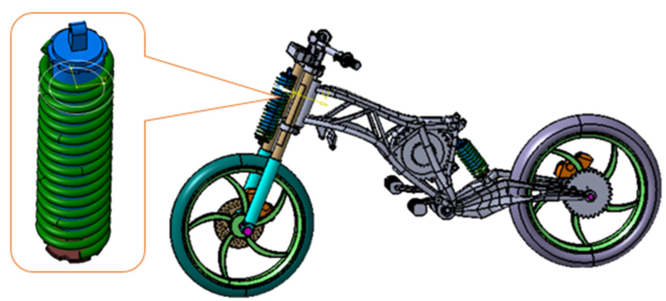
2. Concept and Analysis

Based on the requirements of the design, the energy harvester is represented as a linear induction generator that incorporates shock absorber functions. The magnetic finite element method is then used to analyze the electromagnetic shock absorber.
The energy harvester is represented as a linear induction generator with shock absorber functions based on the design requirements. Figure 1 schematically shows the geometry of conventional shock absorbers in motorcycles. The system transforms the kinetic energy of suspension vibration between the wheel and a sprung load into usable electrical power. The length and outer diameter of the shock absorber are in the range of 250–300 mm and 60–70 mm. To maximize the output power, the length and outer diameter chosen were 300 and 70 mm, respectively. The mechanical air gap chosen was 1 mm.
To address concerns about practical application, because motorcycles are most often running on roads with relatively smooth surfaces during operation, the performance analysis considered was based on such conditions. The vibration frequency of 5 Hz was used to represent a relatively smooth road, while 2 Hz was used to indicate a rougher road surface [21]. The peak-to-peak stroke length was assumed to be 10 mm (as determined in [13]) for a vehicle moving at 70 km/h on a Type B road. Assuming the position of the vibration coil following the time t is:
x = S t p 2 sin ( ω t )
and vibration speed can be calculated as:
v = d x d t = S t p 2 ω = v m a x cos 2 π ft
According to Equation (2), the relation between vibration speed, frequency, and stroke length can be determined as follows:
v m a x = π f S t p m / s
where S t p = 10 mm is the peak-to-peak stroke length and f = 5 Hz is the vibration frequency. These give the maximum vibration speed of 0.157 m/s.
Table 1 provides a summary of the general specifications. The wire was chosen according to Korea Standard KS C 3107:2003. The diameter of the pure copper wire chosen was 0.6 mm, while the insulation thickness was 0.012 mm. This provided wires with a total diameter of 0.644 mm. The radial and axial PMs were made of rare-earth permanent magnets (PMs), NdFeB 40SH and 50SH, respectively, which were chosen due to their high magnetic density (1.26 T and 1.4 T), the relative permeability of r = 1.05 at room temperature and availability.
The eight-slot wight-pole combination model was used to design an electromagnetic shock absorber for the motorcycles in this study. The one-to-one slot-pole ratio was found to produce the maximum output power and power density [19]. Furthermore, the hybrid permanent magnet construction, which is a combination of a classical Halbach array with iron spacers ([44,45]), was employed to improve the performance of the linear generator. The iron spacers were composed of magnetic material and were inserted into the Halbach array to increase the flux linkage on the winding, as well as to increase the flux density in the air gap. The magnetic flux density in the air gap can be significantly increased due to its high relative permeability. The iron core and spacers were made of magnetic carbon steel (S20C) and faced the coil slots directly in the initial alignment position to optimize power [20]. The radial PM assemblies employed a total of ten spacers (see Figure 2).
The number of phases also has an important influence on the power output. Generally speaking, the more coil phases are used, the more power will be produced [16]. In rotating machines and linear (or one-directional motion) machines, the three-phase winding is commonly preferred due to its higher efficiency and better economy. However, in a short-stroke vibrating system, three-phase winding brings problems with voltage and current waveforms. To reduce the complexity of the drive system, each coil was series-connected, using one-phase winding. The external circuit in Figure 3 shows that maximum output power occurs when the load resistance matches the phase-winding resistance.

3. Modeling and Parametric Study of EHSA

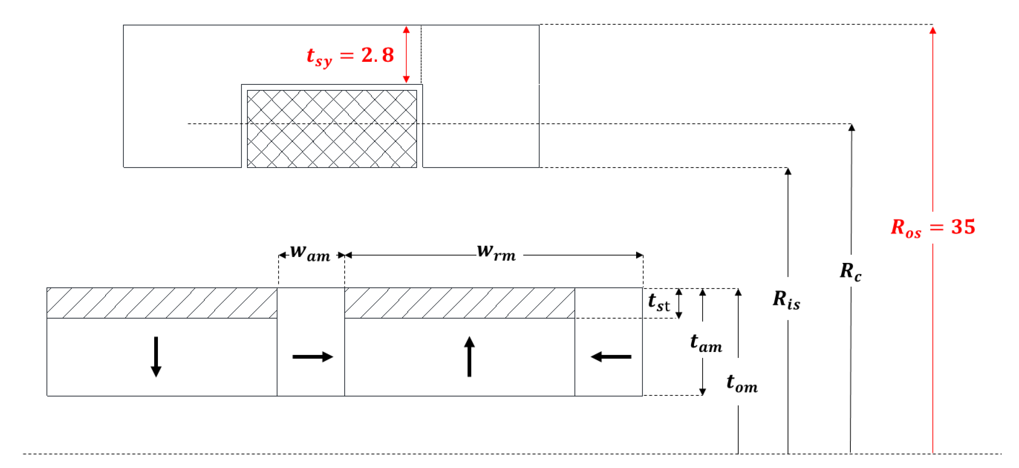
3.1. Mathematical Modeling of EHSA

The output power of EHSA is proportional to the design of the electromagnetic coupling. As a result, parameters such as magnet size, material characteristics, and geometric structure of magnet, coil, and magnetic circuit play an important part in the design process. However, calculating the magnetic field analytically is difficult for ironless systems and even impossible for systems that contain back iron. Therefore, conclusions from publications such as [15,16,19,46] are often based on very simplifying assumptions. Nevertheless, understanding how electrical energy may be retrieved requires a fundamental understanding of magnetic induction theory. The transduction mechanism of an electromagnetic vibration transducer is based on Faraday’s law of induction. According to this principle, any change in magnetic flux across a conductive loop of wire induces a voltage in that loop. Assuming that B r (the radial component of the magnetic flux density) causes the magnetic flux through the coils, the flux ϕ can be written as:
ϕ =   B d S =   B r d S .
The induced voltage is the so-called electromotive force (emf), V e m f , for each coil can be expressed using the Faraday–Lenz law as follows:
V e m f = d ϕ d t = v d ϕ d z
The emf can also be written as [15]
V e m f =   v B r d l =   v t B r z L
where B r is the radial magnetic flux density in a region, and L is the circumferential length of the coil. Given an EMF, the current flowing in a short circuit coil ( R L = 0 ) of an A w cross-section area can be determined as:
I s c =   V e m f R p h a s e =   σ v t B r z A w
while the power generated in each coil in the short circuit is given by:
P   = V e m f I s c = σ v 2 t B r 2 L A w
The circumferential length of coil L can be given by:
L = 2 π R c N
where Rc is the average radius of the coils:
R c =   R o s t s y + R i s 2
N is the number of turns which is determined as
N =   A s l o t k f i l l A w     ~   R o s t s y R i s A w
by fixing the slot fill factor kfill and width of the slot. Thus, by adding Equations (9)–(11) to (8) the peak power will be
P   ~   σ π v 2 t B r     2 R o s t s y 2 R i s 2

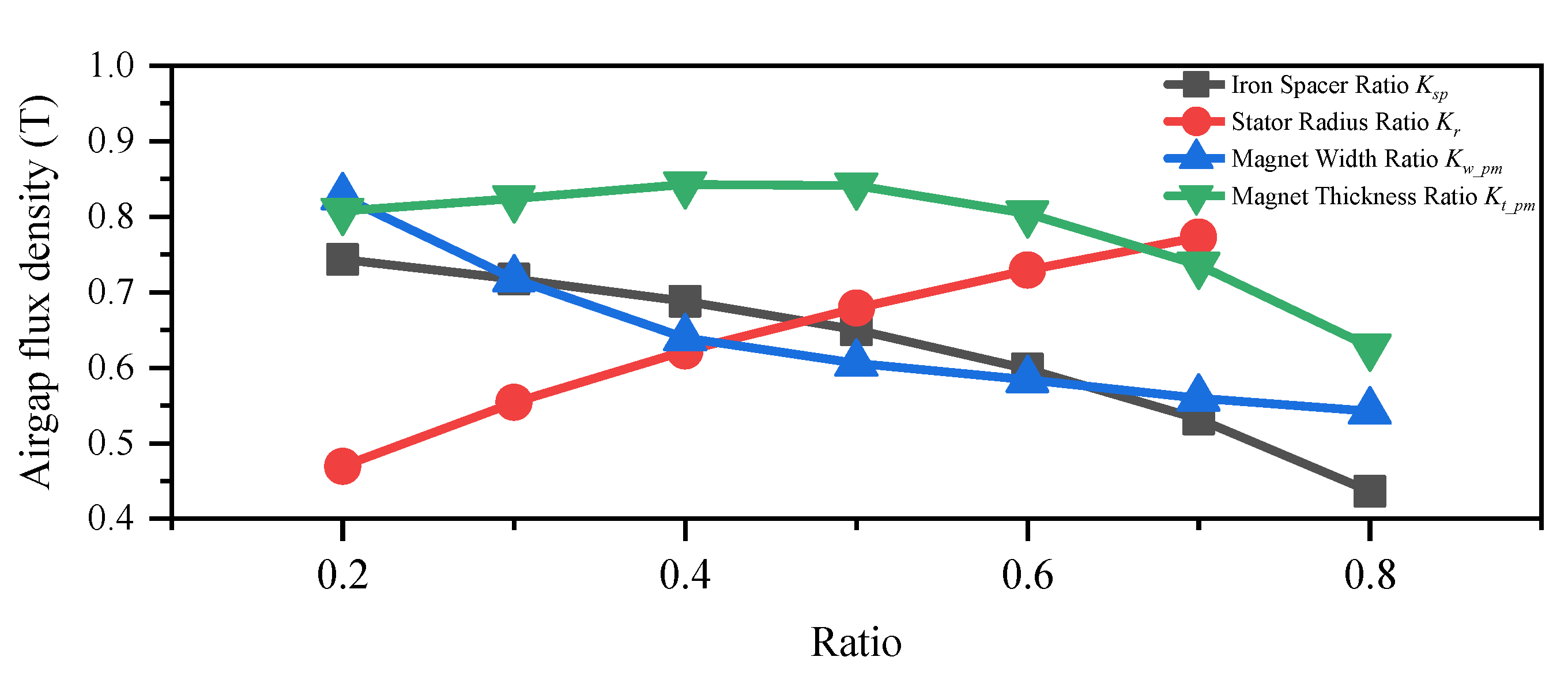
3.2. Parametric Geometry Study
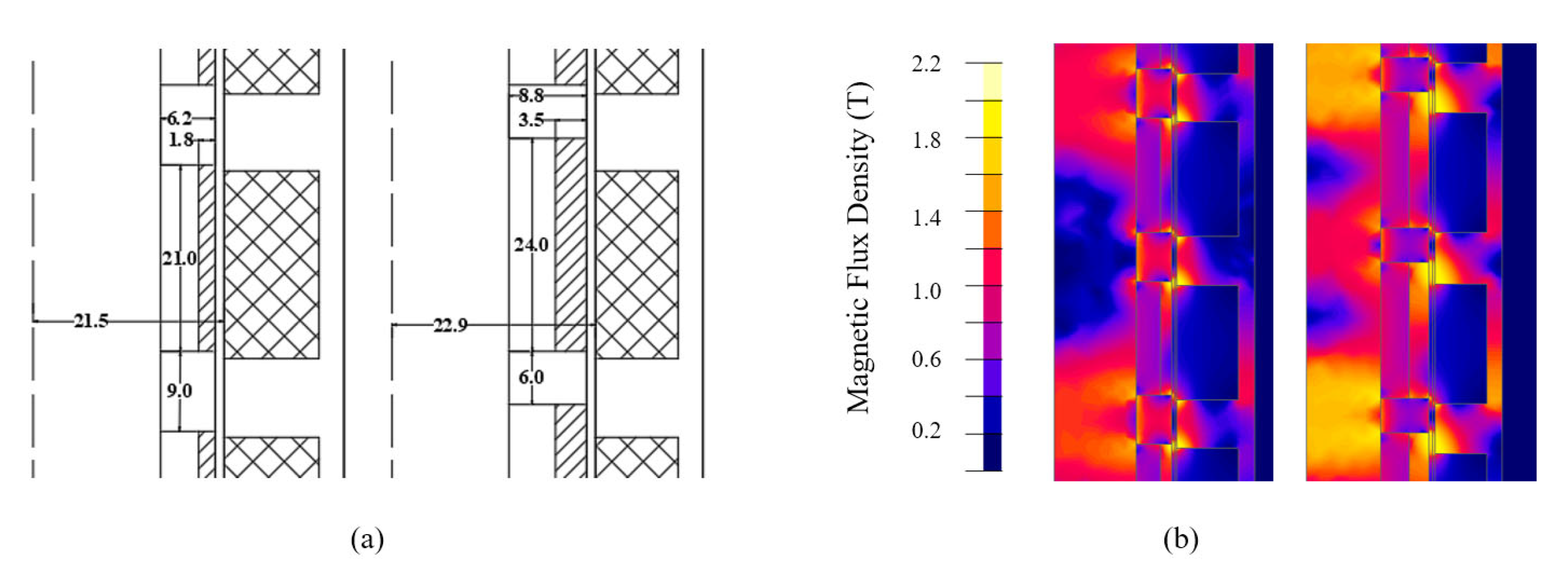
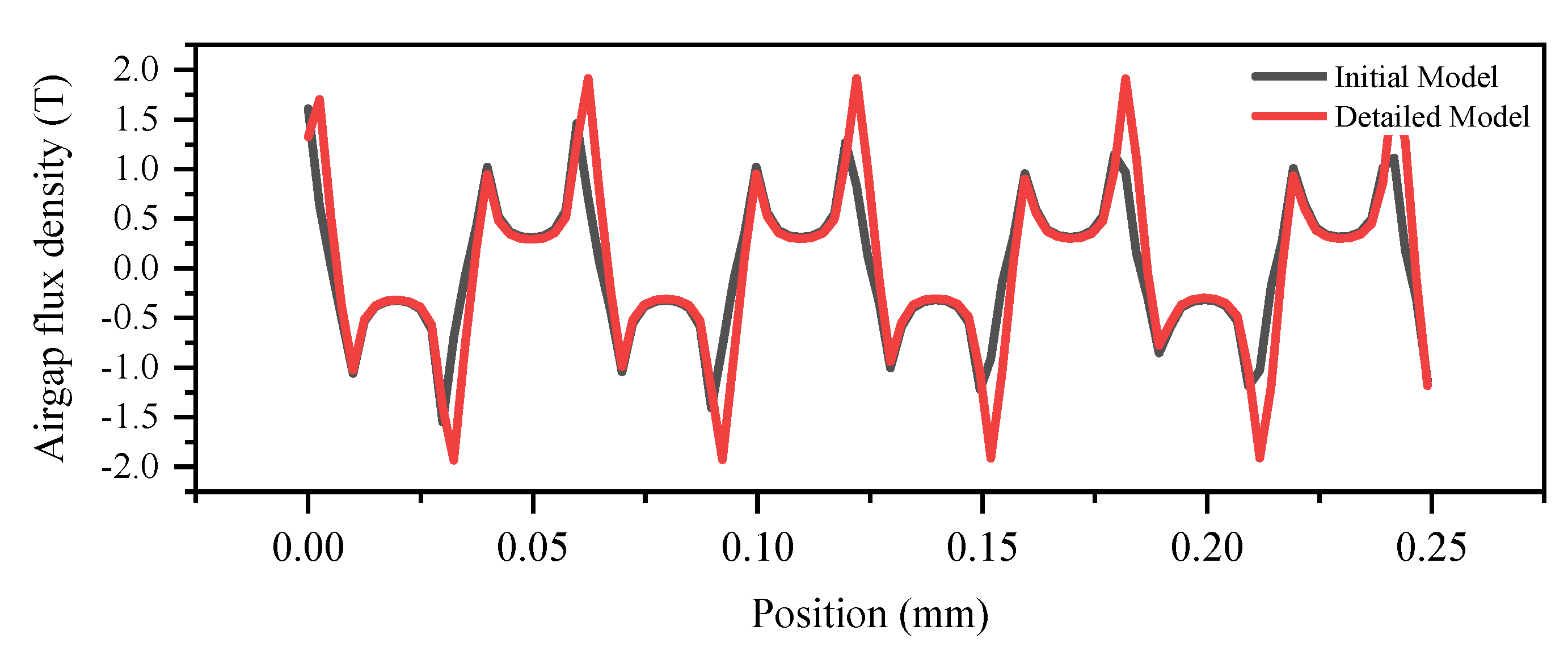
To better understand the effects of various factors on the performance of machines, the individual sensitivity analysis of machine geometrical parameters in this EHSA is investigated in this section. As stated in Equations (8) and (12), the power is proportional to the square of magnetic flux density in the radial direction B r , and to the effective volume of the coil V c o i l = L A w . As a result, there are two ways to increase the power generated by an EHSA. Increasing the magnetic flux density inside the air gap is one option. The alternative option is to increase the effective volume of the coil V c o i l , which is equivalent to shortening the inner stator radius R i s , as shown in Figure 4. The stator radius ratio K r is given by:
K r = R i s R o s
where R i s and R o s is the inner and outer stator radius.
In addition, since the PM is the source of the magnetomotive force that determines the magnetic loading of the motor, the shape of PM, e.g., the thickness and the length of PM are also the key parameters of the EHSA. Therefore, the magnet width and thickness of axial PM, w a m and t a m , which are represented by the ratio K w _ p m and K t _ p m , should be investigated. The magnet width ratio K w _ p m is the ratio of the width of one axial PM w a m and the pole pitch, which was fixed at 30 mm. The magnet thickness ratio K t _ p m is defined as the ratio between the axial magnet thickness t a m and the thickness of a mover t o m :
K w _ p m = w a m w a m + w r m
K t _ p m = t a m t o m
Finally, due to the high relative permeability of the iron spacer attached to radial PM, it will increase the magnetic flux density in the air gap. However, it means decreasing the thickness of radial PM, which will reduce the magnet volume, reduce the magnetic strength and the magnetic flux density in the airgap can be reduced. The effect of thickness of the iron spacer t s p will be studied by the iron spacer thickness ratio K s p , which is defined as
K s p = t s p t a m
It should be noted that when one of the four geometrical parameters varies during the parametric analysis, the others are fixed. Hence, the interaction effects of these parameters are neglected. Table 2 shows the lower and upper parametric values and constants in each study.
Figure 5 shows the magnetic flux density in the radial direction B r and average output power Pout with design parameters. We see that B r always decreases with the decrease of the inner stator radius R i s , which corresponds to an increase in the coil volume. It should be noted that the value of B r in Figure 5 is the root-mean-square (RMS) of the radial magnetic flux density along the air gap at time t = 0 s.
In addition, Figure 6 illustrates the effect of the design parameters on the output power of the EHSA, which is obtained by the integration of the instant power. The output power values of each parametric case are normalized using the values of the initial design. According to Figure 6, the maximum output power at the design parameter stator radius ratio K r , magnet thickness ratio K t _ p m , magnet width ratio K w _ p m , and iron spacer thickness ratio K s p is 0.64, 0.52, 0.25, and 0.4, respectively.

4. Detailed Design

The 2D FE analysis of the detailed design is described in this part. Table 3 and Figure 7a show the geometric parameter and performance of the initial and detailed models. A larger total magnet volume (30%) was used to achieve the required output power due to the increase in magnet thickness t p m from 6.15 to 9.92 mm. The iron spacer thickness t s p is increased significantly from 1.845 to 3.968 mm to achieve more output power. As previously stated, since iron spacers have high relative permeability, increasing the iron spacer will effectively ‘pull’ the flux away from the magnet stack and increase radial flux density, as we can see in Figure 8. The maximum flux density in the air gap at t = 0 s of the initial and detailed model is 1.61 and 1.91 T, respectively, as shown in Figure 8.
Furthermore, the root-mean-square flux density in the air gap at t = 0 s of initial and detailed is 0.43 and 0.69 T, an increase of 0.26 T or 60.5% compared to a 24.5% increase in output power. In addition, Figure 7b illustrates the flux density distribution in both models. The saturation phenomenon still existed and focus on the edge of the stator tooth and iron spacer in both models.
It can be seen from Figure 9 that the maximum output power of the initial and detailed model is 520.5 and 626.7 W, an increase of 106.2 W or 20.4%. Figure 9 also shows a comparison of the cogging force of both models. The maximum cogging force value of the initial and detailed model is 2490 N and 2910 N, an increase of 420 N or 16.9%, respectively. It should be noted that the maximum value of the electromagnetic force from both models is significantly higher than the limitation (≤2000 N). Based on suggestions from car manufacturers, to maintain driving comfort and safety, the threshold force in a medium vehicle (passenger car) and a large vehicle (such as a school bus) must be less than 2000 N and 3000 N, respectively [20]. The higher value of electromagnetic force will lead to unsafety and uncomfortable driving for passengers. According to [19], it should be noted that the one-slot one-pole combination is significantly higher than other slot-pole combinations. However, the one-slot one-pole combination could provide maximum output power compared to others.

5. Conclusions

For this paper, a 120 W electromagnetic shock absorber with a cored-type linear generator and a combination of classical Halbach array and iron spacers was proposed and investigated. Under the rated conditions with 0.157 m/s vibration speed, the maximum and average power were 626.7 and 124 W, respectively. The average power density of the proposed model was 107.3 W/cm3, which satisfied the design target of 104 W/cm3. However, due to the single-variable optimization investigated in this study, the detailed model could not provide a globally optimal design. This led to the utilization of a 30% larger permanent magnet volume to achieve the output power design target. Furthermore, the main drawback of this design is that the large magnetic force leads to discomfort and unsafety when in operation. This drawback was caused by a one-slot one-pole combination which, however, could provide the maximum output power compared to other combinations.
According to the evidence in this paper, the proposed machine topology could be applied in an energy harvesting suspension system for motorcycle applications. In a further study, an optimization algorithm was used to determine the trade-offs between maximum power and power density, minimum volume, and materials used.

Author Contributions

Conceptualization, V.-K.T. and Y.-D.C.; methodology, V.-K.T.; software, V.-K.T.; validation, V.-K.T.; formal analysis, V.-K.T.; investigation, V.-K.T., P.-W.H. and Y.-D.C.; resources, V.-K.T.; data curation, V.-K.T.; writing—original draft preparation, V.-K.T.; writing—review and editing, V.-K.T. and Y.-D.C.; visualization, V.-K.T.; supervision, Y.-D.C.; project administration, Y.-D.C. and P.-W.H.; funding acquisition, Y.-D.C. and P.-W.H. All authors have read and agreed to the published version of the manuscript.

Funding

This research received no external funding.

Institutional Review Board Statement

Not applicable.

Informed Consent Statement

Not applicable.

Data Availability Statement

Not applicable.

Acknowledgments

The research work presented here was carried out at Electric Machines and Drives Research Center, Korea Electrotechnology Research Institute (KERI) and supported in part by the Civil-Military Technology Cooperation Program (No.: 16-CM-EN-17), funded by the Defense Acquisition Program Administration and the Ministry of Trade, Industry & Energy in Korea.

Conflicts of Interest

The authors declare no conflict of interest.

References

  1. Zhang, R.; Wang, X.; John, S. A Comprehensive Review of the Techniques on Regenerative Shock Absorber Systems. Energies 2018, 11, 1167. [Google Scholar] [CrossRef]
  2. Abdelkareem, M.A.; Xu, L.; Ali, M.K.A.; Elagouz, A.; Mi, J.; Guo, S.; Liu, Y.; Zuo, L. Vibration energy harvesting in automotive suspension system: A detailed review. Appl. Energy 2018, 229, 672–699. [Google Scholar] [CrossRef]
  3. Shen, W.; Zhu, S.; Zhu, H.; Xu, Y.-L. Electromagnetic energy harvesting from structural vibrations during earthquakes. Smart Struct. Syst. 2016, 18, 449–470. [Google Scholar] [CrossRef]
  4. Conroy, G.C.; Sideris, P. Exploring energy harvesting and vibration mitigation in tall buildings accounting for wind and seismic loads. Eng. Struct. 2021, 247, 113126. [Google Scholar] [CrossRef]
  5. Khan, F.U.; Iqbal, M. Electromagnetic-based bridge energy harvester using traffic-induced bridge’s vibrations and ambient wind. In Proceedings of the 2016 International Conference on Intelligent Systems Engineering (ICISE), Islamabad, Pakistan, 15–17 January 2016; pp. 380–385. [Google Scholar]
  6. Galchev, T.; McCullagh, J.; Peterson, R.L.; Najafi, K. Harvesting traffic-induced bridge vibrations. In Proceedings of the 2011 16th International Solid-State Sensors, Actuators and Microsystems Conference, Beijing, China, 5–9 June 2011; pp. 1661–1664. [Google Scholar] [CrossRef]
  7. Rahman, A.; Farrok, O.; Islam, R.; Xu, W. Recent Progress in Electrical Generators for Oceanic Wave Energy Conversion. IEEE Access 2020, 8, 138595–138615. [Google Scholar] [CrossRef]
  8. Liu, Y.; Li, S.; Liu, C.; Wang, Y.; Zhou, Y.; Yi, H.; Li, Y.; Chang, H.; Tao, K. Spherical electret generator for water wave energy harvesting by folded structure. In Proceedings of the IECON 2019—45th Annual Conference of the IEEE Industrial Electronics Society, Lisbon, Portugal, 14–17 October 2019; Volume 1, pp. 812–815. [Google Scholar] [CrossRef]
  9. Burhanudin, J.; Abu Hasim, A.S.; Ishak, A.M.; Dardin, S.M.F.B.S.M. A Review of Power Electronics for Nearshore Wave Energy Converter Applications. IEEE Access 2022, 10, 16670–16680. [Google Scholar] [CrossRef]
  10. Kiran, M.R.; Farrok, O.; Mamun, A.A.; Islam, R.; Xu, W. Progress in Piezoelectric Material Based Oceanic Wave Energy Conversion Technology. IEEE Access 2020, 8, 146428–146449. [Google Scholar] [CrossRef]
  11. ClearMotion—Technology. Available online: http://www.clearmotion.com/technology (accessed on 27 March 2022).
  12. Tesla. The Magic of Tesla Roadster Regenerative Braking. Available online: https://www.tesla.com/blog/magic-tesla-roadster-regenerative-braking (accessed on 27 March 2022).
  13. Gonzalez, A.; Olazagoitia, J.L.; Vinolas, J.; Ulacia, I.; Izquierdo, M. An Innovative Energy Harvesting Shock Absorber System for Motorbikes. IEEE ASME Trans. Mechatron. 2021, 1–11. [Google Scholar] [CrossRef]
  14. Suda, Y.; Shiiba, T. A New Hybrid Suspension System with Active Control and Energy Regeneration. Veh. Syst. Dyn. 1996, 25, 641–654. [Google Scholar] [CrossRef]
  15. Scully, B.; Zuo, L.; Shestani, J.; Zhou, Y. Design and Characterization of an Electromagnetic Energy Harvester for Vehicle Suspensions. In Proceedings of the ASME International Mechanical Engineering Congress and Exposition, Lake Buena Vista, FL, USA, 13–19 November 2009; pp. 1007–1016. [Google Scholar] [CrossRef]
  16. Tang, X.; Lin, T.; Zuo, L. Design and Optimization of a Tubular Linear Electromagnetic Vibration Energy Harvester. IEEE ASME Trans. Mechatron. 2014, 19, 615–622. [Google Scholar] [CrossRef]
  17. Karnopp, D. Permanent Magnet Linear Motors Used as Variable Mechanical Dampers for Vehicle Suspensions. Veh. Syst. Dyn. 1989, 18, 187–200. [Google Scholar] [CrossRef]
  18. Singh, S.; Satpute, N.V. Design and analysis of energy-harvesting shock absorber with electromagnetic and fluid damping. J. Mech. Sci. Technol. 2015, 29, 1591–1605. [Google Scholar] [CrossRef]
  19. Duong, M.-T.; Chun, Y.-D.; Han, P.-W.; Park, B.-G.; Bang, D.-J.; Lee, J.-K. Optimal Design of a Novel Single-Phase 8-Slot 8-Pole Tubular Electromagnetic Shock Absorber to Harvest Energy. IEEE Trans. Ind. Electron. 2020, 67, 1180–1190. [Google Scholar] [CrossRef]
  20. Duong, M.-T.; Chun, Y.-D. Optimal Design of a Novel Exterior Permanent Magnet Tubular Machine for Energy Harvesting From Vehicle Suspension System. IEEE Trans. Energy Convers. 2020, 35, 1772–1780. [Google Scholar] [CrossRef]
  21. Liu, C.-T.; Hwang, C.-C.; Lin, W.-P. Design and operational analyses of an electromagnetic hybrid shock absorber system for scooter application. In Proceedings of the 2014 17th International Conference on Electrical Machines and Systems (ICEMS), Hangzhou, China, 22–25 October 2014; pp. 2590–2594. [Google Scholar] [CrossRef]
  22. Wang, W.; Chen, X.; Wang, J. Unsprung Mass Effects on Electric Vehicle Dynamics based on Coordinated Control Scheme. In Proceedings of the 2019 American Control Conference (ACC), Philadelphia, PA, USA, 10–12 July 2019; Volume 2019, pp. 971–976. [Google Scholar] [CrossRef]
  23. Li, Z.; Zuo, L.; Luhrs, G.; Lin, L.; Qin, Y.-X. Electromagnetic Energy-Harvesting Shock Absorbers: Design, Modeling, and Road Tests. IEEE Trans. Veh. Technol. 2013, 62, 1065–1074. [Google Scholar] [CrossRef]
  24. Li, Z.; Brindak, Z.; Zuo, L. Modeling of an Electromagnetic Vibration Energy Harvester with Motion Magnification. In Proceedings of the ASME International Mechanical Engineering Congress and Exposition, Denver, CO, USA, 11–17 November 2011; pp. 285–293. [Google Scholar] [CrossRef]
  25. Zhang, Z.; Zhang, X.; Chen, W.; Rasim, Y.; Salman, W.; Pan, H.; Yuan, Y.; Wang, C. A high-efficiency energy regenerative shock absorber using supercapacitors for renewable energy applications in range extended electric vehicle. Appl. Energy 2016, 178, 177–188. [Google Scholar] [CrossRef]
  26. Liu, M.; Lin, R.; Zhou, S.; Yu, Y.; Ishida, A.; McGrath, M.; Kennedy, B.; Hajj, M.; Zuo, L. Design, simulation and experiment of a novel high efficiency energy harvesting paver. Appl. Energy 2018, 212, 966–975. [Google Scholar] [CrossRef]
  27. Li, Z.; Zuo, L.; Kuang, J.; Luhrs, G. Mechanical Motion Rectifier Based Energy-Harvesting Shock Absorber. In Proceedings of the International Design Engineering Technical Conferences and Computers and Information in Engineering Conference, Chicago, IL, USA, 12–15 August 2012; Volume 6, pp. 595–604. [Google Scholar] [CrossRef]
  28. Zhang, Y.; Zhang, X.; Zhan, M.; Guo, K.; Zhao, F.; Liu, Z. Study on a novel hydraulic pumping regenerative suspension for vehicles. J. Frankl. Inst. 2015, 352, 485–499. [Google Scholar] [CrossRef]
  29. Peng, M.; Guo, X.; Zou, J.; Zhang, C. Simulation Study on Vehicle Road Performance with Hydraulic Electromagnetic Energy-Regenerative Shock Absorber; SAE Technical Paper 2016-01-1550; SAE International: Warrendale, PA, USA, 2016. [Google Scholar] [CrossRef]
  30. Li, C.; Tse, P.W.T. Fabrication and testing of an energy-harvesting hydraulic damper. Smart Mater. Struct. 2013, 22, 065024. [Google Scholar] [CrossRef]
  31. Zhang, Y.; Chen, H.; Guo, K.; Zhang, X.; Li, S. Electro-hydraulic damper for energy harvesting suspension: Modeling, prototyping and experimental validation. Appl. Energy 2017, 199, 1–12. [Google Scholar] [CrossRef]
  32. Li, C.; Zhu, R.; Liang, M.; Yang, S. Integration of shock absorption and energy harvesting using a hydraulic rectifier. J. Sound Vib. 2014, 333, 3904–3916. [Google Scholar] [CrossRef]
  33. Huang, B.; Hsieh, C.-Y.; Golnaraghi, F.; Moallem, M. Development and optimization of an energy-regenerative suspension system under stochastic road excitation. J. Sound Vib. 2015, 357, 16–34. [Google Scholar] [CrossRef]
  34. Amati, N.; Festini, A.; Tonoli, A. Design of electromagnetic shock absorbers for automotive suspensions. Veh. Syst. Dyn. 2011, 49, 1913–1928. [Google Scholar] [CrossRef]
  35. Wang, Z.; Zhang, T.; Zhang, Z.; Yuan, Y.; Liu, Y. A high-efficiency regenerative shock absorber considering twin ball screws transmissions for application in range-extended electric vehicles. Energy Built Environ. 2020, 1, 36–49. [Google Scholar] [CrossRef]
  36. Liu, Y.; Xu, L.; Zuo, L. Design, Modeling, Lab, and Field Tests of a Mechanical-Motion-Rectifier-Based Energy Harvester Using a Ball-Screw Mechanism. IEEE ASME Trans. Mechatron. 2017, 22, 1933–1943. [Google Scholar] [CrossRef]
  37. Structure Design and Parameter Matching of Ball-Screw Regenerative Damper. Available online: https://www.researchgate.net/publication/289905771_Structure_design_and_parameter_matching_of_ball-screw_regenerative_damper (accessed on 26 July 2022).
  38. Xie, L.; Cai, S.; Huang, G.; Huang, L.; Li, J.; Li, X. On Energy Harvesting From a Vehicle Damper. IEEE/ASME Trans. Mechatron. 2020, 25, 108–117. [Google Scholar] [CrossRef]
  39. Bowen, L.; Vinolas, J.; Olazagoitia, J.L. Design and Potential Power Recovery of Two Types of Energy Harvesting Shock Absorbers. Energies 2019, 12, 4710. [Google Scholar] [CrossRef]
  40. Bowen, L.; Vinolas, J.; Olazagoitia, J.L.; Otero, J.E. An Innovative Energy Harvesting Shock Absorber System Using Cable Transmission. IEEE/ASME Trans. Mechatron. 2019, 24, 689–699. [Google Scholar] [CrossRef]
  41. Casavola, A.; Di Iorio, F.; Tedesco, F. A multiobjective H∞ control strategy for energy harvesting in regenerative vehicle suspension systems. Int. J. Control 2017, 91, 741–754. [Google Scholar] [CrossRef]
  42. Di Iorio, F.; Casavola, A. A multiobjective H∞ control strategy for energy harvesting while damping for regenerative vehicle suspension systems. In Proceedings of the 2012 American Control Conference (ACC), Montreal, QC, Canada, 27–29 June 2012; pp. 491–496. [Google Scholar] [CrossRef]
  43. Scruggs, J. Multi-objective nonlinear control of semiactive and regenerative systems. In Proceedings of the 2010 American Control Conference, Baltimore, MD, USA, 30 June–2 July 2010; pp. 726–731. [Google Scholar] [CrossRef]
  44. Duong, M.-T.; Chun, Y.-D.; Bang, D.-J. Improvement of Tubular Permanent Magnet Machine Performance Using Dual-Segment Halbach Array. Energies 2018, 11, 3132. [Google Scholar] [CrossRef] [Green Version]
  45. Zhu, Z.Q.; Shuraiji, A.L.; Lu, Q.F. Comparative Study of Novel Tubular Partitioned Stator Permanent Magnet Machines. IEEE Trans. Magn. 2016, 52, 1–7. [Google Scholar] [CrossRef]
  46. Zuo, L.; Scully, B.; Shestani, J.; Zhou, Y. Design and characterization of an electromagnetic energy harvester for vehicle suspensions. Smart Mater. Struct. 2010, 19, 045003. [Google Scholar] [CrossRef] [Green Version]
Figure 1. Conventional shock absorbers on a motorcycle.
Applsci 12 08688 g001
Figure 2. Configuration of the eight-slot eight-pole electromagnetic shock absorber.
Applsci 12 08688 g002
Figure 3. External circuit of the eight-slot eight-pole model.
Applsci 12 08688 g003
Figure 4. Design parameter of EHSA with the stator outer radius Ros and stator yoke thickness tsy is fixed.
Applsci 12 08688 g004
Figure 5. Variation of flux density in the air-gap Br design parameters.
Applsci 12 08688 g005
Figure 6. Variation average output power Pout with design parameters.
Applsci 12 08688 g006
Figure 7. Geometric dimensions (a) and the flux distribution at t = 0 s of initial model (left) and the detailed model (right) (b).
Applsci 12 08688 g007
Figure 8. Flux density in the air-gap at t = 0 s of the initial model and the detailed model.
Applsci 12 08688 g008
Figure 9. Output power and Cogging force of the Initial and the Detailed Model.
Applsci 12 08688 g009
Table 1. Design specifications.
ItemValue
Motorbike mass (kg)250
Vibrating speed, v (m/s)0.157
Stroke length peak-to-peak Stp (mm)10
Vibrating frequency, f (Hz) 5
Maximum length, L (mm)300
Outer diameter (mm)70
Pole pitch/Slot pitch (mm)30
Mechanical air gap (mm)1
Axial PMs material 50SH: Br = 1.40 T; μr = 1.05
Radial PMs material 40SH: Br = 1.26 T; μr = 1.05
Electrical steel S20C
Wire diameter, wd (mm)0.6
Slot fill factor 0.5
Table 2. The lower and upper parametric values and constants in each study.
No.ParameterLowerUpperConstant
1Kr0.20.7Kt_pm = 0.7, Kw_pm = 0.3, Ksp = 0.3
2Kt_pm0.20.8Kr = 0.6, Kw_pm = 0.3, Ksp = 0.3
3Kw_pm0.20.8Kt_pm = 0.7, Kr= 0.6, Ksp = 0.3
4Ksp0.20.8Kt_pm = 0.7, Kw_pm = 0.3, Kr= 0.6
Table 3. Comparison of Initial and Detailed Design.
ItemTargetInitialDetailed
Stator radius ratio Kr 0.60.64
Magnet thickness ratio Kt_pm 0.70.52
Magnet width ratio Kw_pm 0.30.25
Iron spacer thickness ratio Ksp 0.30.4
Inner stator radius Ris (mm) 21.522.9
Magnet thickness trm (mm) 6.159.92
Axial PMs thickness tam (mm) 9.07.5
Radial PMs width wrm (mm) 21.022.5
Iron spacer thickness tsp (mm) 1.8453.968
Min average output power (W)12099.6124
Min average power density (W/cm3)10486.3107.3
Publisher’s Note: MDPI stays neutral with regard to jurisdictional claims in published maps and institutional affiliations.

