1. Introduction
Thermal protection is one of the most important aspects in condition monitoring of electrical machines. An overheating will carry the deterioration of fundamental components of the machine, such as the stator winding, insulation, core or bearings [
1].
Currently, embedded temperature sensors inside the motor are the most utilized alternative in medium/high power electrical machines. On the other hand, the integration of these sensors normally increases the number of faults, due to the disintegration of the connections, noise interference, and their large time constant.
In recent times, several research works have proposed different kind of strategies for the temperature estimation in different points of the machine [
2]. These methods can be classified into two main categories: thermal model-based approaches and estimation of the temperature from the resistance [
3,
4,
5,
6].
Thermal model-based approaches are based on a thermal circuit to estimate the temperature in the machine [
7,
8]. Thermal parameters are calculated from machine dimensions or characterized from offline experiments. However, the thermal parameters are not constant for the different operation points, so they should be fitted for different operation conditions. This kind of method cannot deal with cooling problems or insulation deterioration. Furthermore, initial temperature needs to be known.
On the other side, the methods that estimate the temperature from the resistance variation are not dependent on the operation condition and the cooling status. They are based on the relationship between resistance and temperature as it is shown in [
9]. These methods can be divided in two main groups: a machine model-based approach and signal injection approach [
10,
11].
Apart from the aforementioned main groups, methods based on artificial intelligence and data have emerged too [
12]. Machine model-based approaches use the fundamental excitation and the machine model to estimate the resistance. The main drawback to this method is that it is usually too sensitive to unknown machine parameters and their variations. Several models have been proposed in the literature but they are generally limited to a small range of speed [
13,
14]. Thus, as the approach is limited to a range of speed and torque, the machine is not protected in all the operation points.
On the other hand, signal injection approaches excite the machine with a signal, which can be DC or AC, to estimate the resistance [
15]. This approach provides an accurate estimation of the resistance in the whole speed region. Different strategies based on the DC and AC injection have been published. AC signals are injected for the stator resistance estimation in [
16,
17,
18]. The injected voltage value needs to be estimated or measured, so these methods are not desirable. Furthermore, the AC signal injection algorithm is dependent on machine parameters which can change with the temperature.
Finally, a DC injection strategy has been proposed in references [
9,
10,
19,
20,
21,
22,
23]. In the strategies proposed in [
19,
20], additional hardware is needed for the DC offset generation. On the other hand, there is no need of hardware in [
9,
10,
21,
22] because the signal is injected through the inverter. On the other hand, in reference [
21], a scalar control is considered, but the proposed implementation at not constant loads turns complicated. The injection through the inverter suffers from some undesired effects. The inverter dead-time effects are studied in [
9]. It only considers the dead-time effect, and the strategy is difficult to implement at not constant load. The dead-time is introduced in the commutation of power switches to avoid a shortcut in the DC bus. In reference [
22] the effect of a closed loop control and the inverter non-idealities are considered in the injection, however, the DC voltage estimation is needed. The hardware requirement for the obtaining of the exact duty cycle for the voltage estimation is very high. Overmodulation and discontinuous PWM methods should also be considered using this method. The implementation of this method could be possible with the proper hardware and the required tuning effort. Unfortunately, this implementation becomes even more complicated in applications such as railway traction units, where all this precision hardware is not usually installed. Another DC injection strategy can be found in [
10], where the authors propose some simplifications in order to compensate the non-idealities of the inverter. Unfortunately, these simplifications are not valid for medium-/large-sized machines. In addition to the DC injection strategy proposed in [
23], a second-order harmonic current is injected to compensate the non-linearities. The harmonic component phase varies according to the load. The main references to estimate the temperature from resistance are summarized in
Table 1.
This paper proposes a novel injection strategy for stator resistance estimation for thermal protection purpose. A controlled DC signal is injected in the machine through the inverter, adding an offset in the control drive. This strategy uses a double dead-time injection in order to compensate the non-linear voltage drop in the inverter due to the dead-time effect. Other detected non-idealities of the inverter injection are compensated for easily with a look-up table. The proposed solution solves the limitations of other methods, as it can be applied to the whole region of speeds, and it compensates the dead-time effect. The injection strategy, the modeling math and the validation experiments are presented in this publication.
2. Signal Injection Principle and Considerations
It is based on the relationship between temperature and resistance. As the temperature of the stator windings is related to the stator resistance by the Equation (1) from [
9].
where ∝ is the winding material thermal coefficient. Copper is the most common winding material in electric machines, being ∝ ≈ 0.0039.
and
are the actual stator temperature and the cold state temperature, respectively.
and
are the stator resistance and the cold state stator resistance, respectively.
Thus, based on this relation, an online estimation of the stator resistance value allows to calculate the temperature.
From the stator voltage equation of the induction machine, the DC equation in steady-state results in the simple Equation (2).
Thus, the stator resistance only depends on the DC voltage and the DC current values. The DC offset of the current can be obtained from the sensors installed generally in the control systems. However, the voltage signal is generally not available unless an extra hardware is implemented, so it needs to be estimated.
An injection strategy is presented in this paper, where a controlled DC current is injected and the needed voltage to generate this DC current is analyzed. There are two main reasons for using a controlled current injection.
From one side, the voltage drop in the inverter depends on the current DC level. The DC level will change with the temperature, so the adjustment of any estimation algorithm will be also dependent on the temperature.
From the other side, if a constant voltage is injected, the current will decrease in function of the temperature. At medium/high size machines, the stator resistance is usually very small. This supposes that a considerable change in temperature can cause a small DC current level change. At high temperatures, the current will decrease, so the precision will be smaller.
In order to have a constant DC current, a controllable injection strategy has been implemented, where the injected offset is controlled, as it is shown in
Figure 1. The offset current of the phases “a” and “b” is fixed using a PI controller. To control the current offset, the voltage signal introduced in the modulator is adjusted. In this implementation, the current of the phases “a” and “b” is obtained with a low-pass filter (LPF).
From one side, a current reference is injected in “a” phase and the same but negative reference is injected in phase “b”. Making this, an offset is generated only in the phases “a” and “b”, making the offset of the phase “c” equal to 0. In this way, the three-phase system can be considered as a two-phase system. Furthermore, as the DC voltage level at two phases is equal, it is enough to take into account just one phase, considerably simplifying the developed equations. In order to equilibrate the injection in the first two phases, a voltage reference equal to 0 is injected in the phase “c” so it can be ensured that the middle point voltage will be equal to 0.
The controller will detect the introduced offset as a perturbation, and it will try to eliminate it. In order to hide the injected offset to the controller, the feedback current signals are filtered with an LPF.
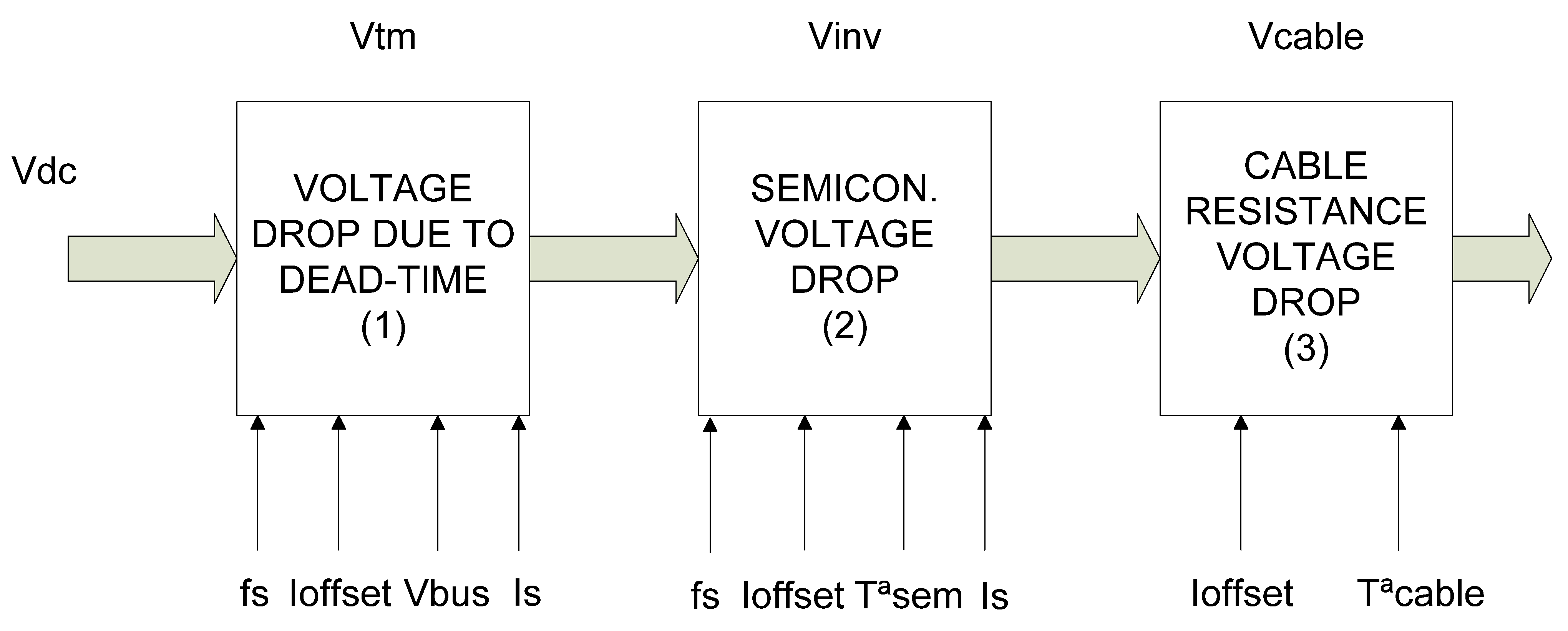
In order to avoid the use of extra hardware, the offset injection is performed through the inverter. However, the introduced DC voltage will be affected by different non-idealities present in the inverter. These non-idealities are identified as the dead-time and the voltage drop in semiconductors. Aside from the voltage drop in the inverter, there is also a voltage drop in the cable that connects the inverter and the machine. All these voltage drops should be compensated for in order to estimate the stator resistance value using the Equation (2).
These voltage drops in the inverter are represented in
Figure 2. The voltage drop due to the dead-time is dependent on the dead-time value, the DC current offset level, the bus voltage level and the stator current. The dead-time is introduced in the commutation of the IGBTs to avoid two switches in the same arm conducting at the same time, and thus avoiding a shortcut in the DC bus. This phenomenon produces a voltage drop in the injected offset; as previously mentioned, it is dependent on the duty cycle, the current offset level and the bus voltage.
The voltage drop in the semiconductors depends on the current DC value, the temperature of the semiconductors and the stators current level. Finally, the series resistance drop depends in the current DC offset and the temperature of the cable. As a constant current offset is injected, the dependency to this parameter can be eliminated.
Analyzing the parameter dependency in the voltage drop due to the dead time, it can be observed that the parameters “dead-time value” and “bus voltage” can be made constant. In this way, their compensation is easy and the dependency of these variables can be eliminated. Therefore, the dead-time voltage drop depends only in the stator current value. Unfortunately, this parameter can change in amplitude, frequency and phase. A small change in any of these variables can modify the voltage drop due to the dead time.
From the other side, analyzing the variables that affect the voltage drop in the semiconductors, the temperature is usually measured and can be compensated for easily. Thus, it will only depend on the stator current. Fortunately, the change in this parameter is less sensitive in the change in the voltage drop in semiconductors than in the dead-time voltage drop, making its compensation easier. Finally, the voltage drop in the cable can be easily compensated for using a simple thermal model. Thus, the major difficulty comes in the compensation of the dead-time voltage drop.
In the present publication, a new dead-time effect elimination method is exposed. It has been eliminated using a double dead-time injection. The voltage drop in the semiconductors can be compensated for easily with a look-up table in function of the stator current level. Thus, the voltage in the machine terminals can be estimated easily compensating the voltage drop in the inverter.
3. Optimization of the Injection Using Double Dead-Time Strategy
In order to eliminate the effect of the dead time, a new injection strategy has been designed. This strategy is based on the injection of a controlled current at two different dead times. Using the current control injection strategy, previously presented in
Figure 1, the current DC value is maintained constant during the injection.
In
Figure 3, the double dead-time strategy is described. First, a controlled current signal is injected with the first dead-time value (
Ttm1). As soon as the current arrives to the steady state, the injected value
Vinj1 is stored. The dead-time value is changed to T
tm2 and the injected voltage
Vinj2 is stored after the transition time. The injected voltage eliminating the dead-time effect is calculated. Once this value is obtained, the stator current and the temperature in the semiconductors is measured and the voltage drop in the semiconductors is estimated. In the other side, the voltage drop in the cable is estimated and the voltage at machine terminals is calculated. The mathematical approach is hereinafter described.
First, the dead-time voltage drop will only be considered. As it has been mentioned, the injection is performed considering the controlled way; the estimation of the three-phase system can be made considering only one phase. Thus, the equation of the injected voltage in machine terminals can be expressed as (3).
where
VDC_out is the voltage at the machine terminals;
Vinj represents the injected voltage by inverter;
NDT is the difference between the dead-time cycle number in the positive side and the negative side of the current; and
Dtm is the dead-time duty cycle.
The value NDT could change in function of the working point of the machine. This value is dependent on the voltage, current and phase of the feeding signal of the machine. The on-line estimation of this value during the control is very complicated due to the difficulty of detecting the zero crossing and the delay in the switching of the IGBTs of the inverter.
For this reason, a double injection strategy has been designed to compensate the dead-time voltage drop. This strategy consists in the injection of two different signals at two different dead-time values. These two injections are made at the same working point, so the
NDT will not change in most of the cases. If the dead-time suffers a small change, the current, voltage and phase of the feeding signal will barely change. In (4), the equations of the double injection are shown.
where
VDCout1 and
VDCout2 are the voltage at the terminals of the machine for the two different injections respectively;
Vinj1 and
Vinj2 are the injected voltages for the two different dead-times;
Ttm1 and
Ttm2 are the two dead-time values.
Considering that the two injections are made with the same stator resistance value and the same DC current offset, the VDCout1 and VDCout2 values will be identical. If the injections are made with a short time interval, the resistance will be practically the same due to the low dynamic of the temperature.
As
VDCout1 and
VDCout2 are equal, the Equation (4) transforms in (5).
The system is formed by two equations and two unknown values. Resolving the system, the value
VDC_out could be obtained with the simple Equation (6).
With this strategy the dead-time effect can be solved. This is the non-ideality that most affects the injected voltage. However, the injection is also affected by the voltage drop at semiconductors and the cable that connects the inverter with the machine. These two variables are introduced in Expression (6) to obtain the final Equation (7).
To compensate the cable voltage drop, a simple thermal model of the cable can be implemented. Using this model, the value of Vcable is estimated.
The value of Vsemi is unknown and it depends on the current offset, the current RMS value, the stator frequency and the temperature of the semiconductors. From one side, adjusting the commutation frequency in function of the stator frequency, the dependency on the stator frequency is eliminated. From the other side, the double dead-time injection is made with the same current offset. Thus, a look-up table for different current and temperature values could be implemented to obtain this value. The variation of Vsemi does not suffer large variation with respect to the change in the mentioned parameters, so the look-up table does not need to have a big number of measurements.
In order to tune this look-up table, the machine is run at different stator current levels with the same current DC value. Measuring the temperature of the machine stator, the value of VDC_out could be estimated for the different working points.
Applying the double injection strategy, the look-up table could be tuned using the Equation (8).
4. Experimental Validation
The experimental setup and results are presented in this section.
4.1. Experimental Setup
In order to guarantee the validity of the designed double dead-time algorithm, it has been validated in a test bench. The
Table 2 shows the specifications of the metro machine used for the validation of the temperature estimation algorithm.
The designed algorithm has been tested in a test bench composed by commercial elements, used in the metro of Bilbao by the company CAF Power & Automation. In this section the platform used for the validation of the strategy is described. The test bench is formed by two confronted squirrel cage induction machines. One machine is used as the traction motor and the other one is the load. The machines are fed by two VSI (“Voltage Source Inverter”), one for each machine. The control unit is composed by a DSP (“Digital Signal Processor”) and a FPGA (“Field-Programmable Gate Array”). The structure is shown in
Figure 4.
To estimate the stator resistance on-line, the temperature of the stator is measured. For this purpose, different PT100 sensors have been installed in different parts of the machine. The algorithm has been implemented in a classical vector control. The tuning of the PI parameters of the injection strategy and the filter used to obtain the current offset has been made putting special interest into the estimation time. The implemented low-pass filter is a fourth-order filter with a cut-off frequency of 6.6 Hz. The current offset controller has a proportional gain (Kp) of 1 and an integral gain of (Ki) of 5.
These parameters have been obtained in a manual tuning, looking for a low oscillation but giving more importance to a fast estimation, especially in the dead-time change. The injected voltage for the required current offset at the two different dead times has to be performed at the same working point. In order to avoid a condition variation during the estimation process, the algorithm has to work as fast as possible. This can be achieved using a low order filter or increasing the controller gains. However, this will cause an increment in the oscillation current DC component so a compromise between fast estimation and offset oscillation has been found.
4.2. Characterization of the on-Line Injection
In order to use the Equation (7), it is necessary to know the parameters Vsemi and Vcable. Different tests demonstrated that the temperature of the resistance of the cable did not practically change, so in the experiment Vcable will be constant with a value of 0.045 V. In this sense, only the voltage drops at semiconductors (Vsemi) need to be tuned. This is carried out using Equation (8).
The Vsemi value will be different for different working points. As it has been mentioned, with the designed strategy the voltage drop will be only dependent of the stator current. From the measured temperature, the resistance of the stator can be estimated. Multiplying the stator resistance and the current offset, VDC_out is obtained.
In order to tune the semiconductor voltage drop, the machine has been run at different working points and the double dead-time injection algorithm has been applied.
In
Figure 5, the injection at a fixed working point is shown. The double dead-time injection strategy has been applied and the injection values
Vinj1 and
Vinj2 have been monitored. First, the injection voltage value for a dead time of 10 us is plotted. At a time equal to 26 s, the dead-time is changed. From this point, after a transitory state of 1 s, the injection voltage value for the dead-time of 13 us is plotted.
To obtain the mean value, a running mean value calculator has been used. Applying the same strategy at different working points, Vsemi is computed and stored.
The specific temperature of the semiconductor could vary the Vsemi value. Several tests have been performed with a constant torque at different semiconductors temperature obtaining a very similar Vsemi value. Then, it is deduced that for the inverter of the experimental test bench, the effect of the semiconductor temperature can be considered negligible.
Some analyses have been carried out at steady state with constant torque in a higher stator temperature. Both the machine and the converter have correctly dissipated the losses. Analyzing the total increment of Vsemi, it can be considered constant independently of the stator temperature. In this experiment, it is considered that the parameter Vsemi is barely affected by the semiconductor’s temperature.
In
Figure 6, the DC currents of the phases “a” and “b” are shown; the “a” phase offset is 10 A and the “b” phase offset is −10 A.
The machine has been run at different working points of torque and speed, and the different
Vsemi values have been computed. Adapting the commutation frequency in the function of the stator frequency, the voltage drop in semiconductors in the function of the speed can be immunized. In
Figure 7, the calculated
Vsemi values for different working conditions are represented. The shown values are an average of the
Vsemi value obtained at different temperatures.
The calculated
Vsemi values changed for different torque values as expected. The increase in the torque produces an increase in the stator RMS current value, producing a different voltage drop in the semiconductors. On the other side, the change in the stator frequency barely changes the stator RMS current, producing a similar voltage drop in the semiconductors for different stator frequencies. Thus, a mean value for each torque is stored in a look-up table as shown in
Table 3.
4.3. Experimental Results
Once the Vsemi values for different working points are calculated, they are stored in a look-up table. To estimate the temperature, the injection is made at the dead times of 10 us and 13 us, and the DC current was fixed in 10 A. It should be taken into consideration that during the estimation, the point has to be maintained constant. If the working point change before the estimation is finished, the sample will be discarded, and a new estimation will be carried out as soon as a working steady state is reached.
Table 4 summarizes a comparison between the DC voltage measured (
VDC_out_meas) and the estimated value
VDC_out given by Equation (7) for a stator frequency of 30 Hz. In a similar way, the comparison is performed for the stator resistance for both cases. The injected DC current has been equal to 10 A in all the tests. The presented deviations in Rs are low, below an absolute value of 2 mΩ, which represent deviations up to 5 °C, which is acceptable for the application. Up to 10 °C deviation could be accepted.
The
Figure 8 the stator current during the injection.
Figure 9 shows the estimated temperatures compared to the measured temperatures for two different working points. The
Vsemi values previously presented in the
Table 3, are stored in a look-up table for estimation. These values are an average of the
Vsemi values obtained at these working points at different temperatures.
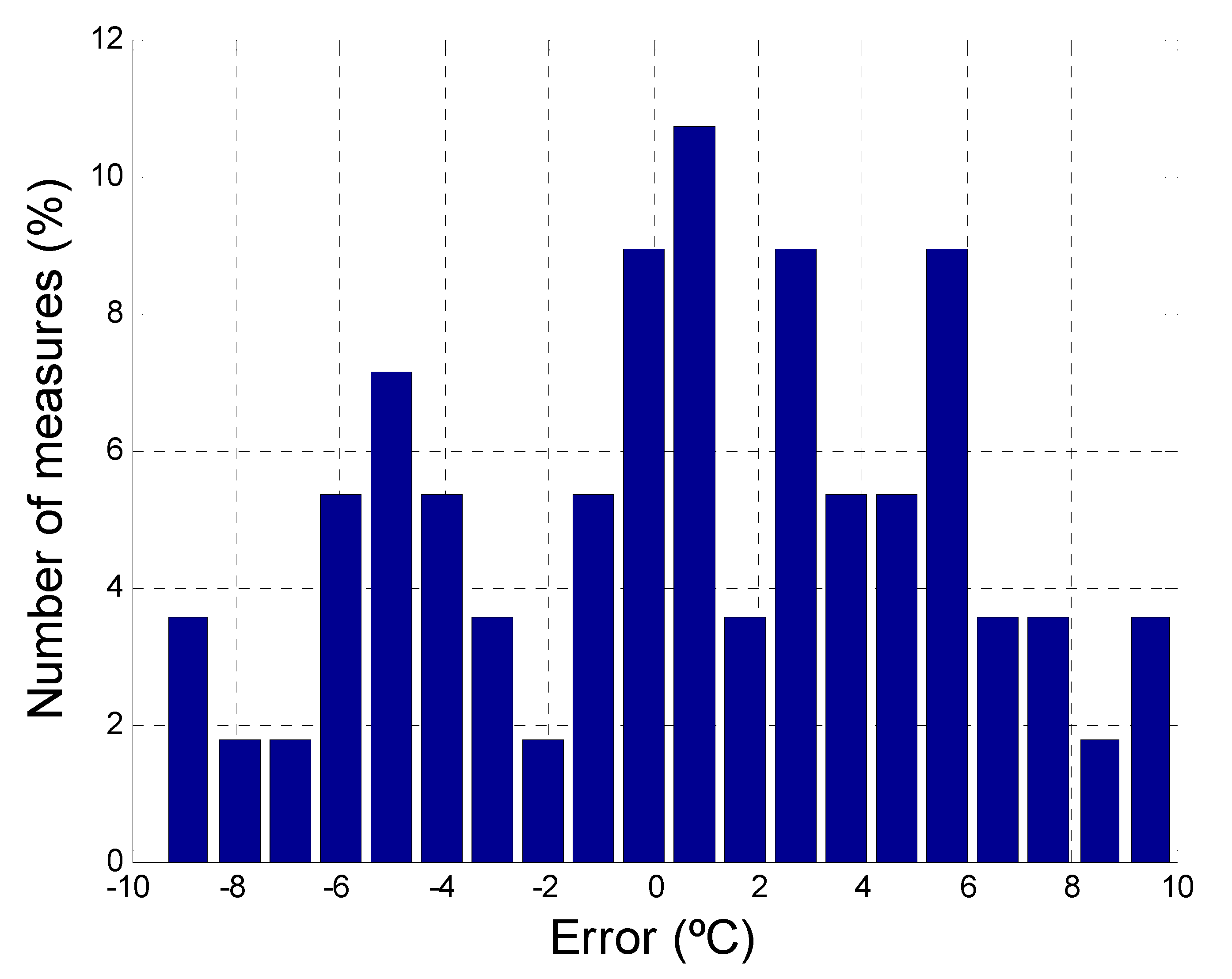
The injection algorithm has been tested at different working points. In all cases, the temperature error committed in the estimation was maintained in the range of ±10 °C. Finally,
Figure 10 shows the histogram of the errors for the different measures. The distribution of the errors is quite constant around the range ±10 °C.
5. Discussion
A temperature-monitoring algorithm based on a DC injection and stator resistance estimation is presented in this paper. This strategy permits to eliminate the temperature sensors in the machine, and as consequence, the potential faults of the sensors, increasing the reliability of the system. The main difficulty of DC injection methods resides in the estimation of the DC voltage component of the commutated voltage, as there are not voltage sensors. Thus, an injection strategy should be proposed for an accurate and reliable DC voltage value.
Furthermore, the different methods previously presented have limitations, as is shown in
Table 5. The double dead-time strategy solves these limitations; as it is not dependent on machine parameters, it can be used in the whole region of speeds and it is able to compensate the dead-time voltage drop, which is a key point for an accurate estimation in DC injection methods. Moreover, additional hardware is not needed.
A novel strategy based on a double dead-time injection is presented. A symmetric DC current injection is applied to two phases. Furthermore, this original method is capable to compensate the voltage drop caused by the dead-time effect of the inverter. The dead time is introduced in the commutation of the IGBTs to avoid a shortcut in the DC bus. This phenomenon produces a voltage drop in the injected offset, and it depends on the duty cycle. This strategy avoids computing the number of switching cycles for the positive and negative cycles of the fundamental signal. It should be noted that this computation is quite difficult to compute correctly under real working conditions where the current waveform has a high number of ripples, sub-oscillations and frequency oscillations
Other non-idealities of the inverter such as the voltage drop in the semiconductors are easily compensated for with a simple look-up table. The voltage drop in the cable can also be easily compensated for.
The presented method has been implemented in a typical closed loop vector control. The injection is performed introducing a controlled current offset, which simplifies the estimation. An offset is injected in one phase and the same but negative is injected in another phase. In this way, the system can be analyzed as a one-phase system.
The presented algorithm needs no extra measurement hardware because it only uses the already existing current sensors. It can be implemented in a variable load system and is suitable for medium/high size machines. The estimation is performed in some seconds avoiding a perturbation in the system. This strategy has been designed for thermal protection of railway traction units where there are some working-point steady-state periods that can be used to make the estimation. However, the strategy could be implemented in any other system that fulfils this requirement.
The system has been validated in a real railway test bench. The maximum estimation error is around ±10 °C, so the validation of the system for thermal protection is ensured.
In conclusion, a novel signal injection strategy to estimate the stator resistance of induction motors is presented. This strategy allows the online temperature estimation for the protection of motors, and it can be applied to the whole range of speeds. A double dead-time DC signal is injected in the machine, but the method compensates the voltage drops due to dead-time effect, this being a key point for an accurate estimation of the stator resistance. Furthermore, additional hardware is not needed. The strategy has been validated in a real railway test bench.


