Article

Effect of the Number of Circuits on a Finned-Tube Heat Exchanger Performance and Its Improvement by a Reversely Variable Circuitry

1
School of Energy and Power Engineering, Xi’an Jiaotong University, Xi’an 710049, China
2
Qingdao Haier Air Conditioner General Corp., Ltd., Qingdao 266103, China
*
Author to whom correspondence should be addressed.
Appl. Sci. 2022, 12(18), 8960; https://doi.org/10.3390/app12188960
Submission received: 7 July 2022 / Revised: 23 August 2022 / Accepted: 1 September 2022 / Published: 6 September 2022
(This article belongs to the Section Applied Thermal Engineering)

Abstract

:
The finned-tube heat exchanger (FTHX) works better with more circuits as an evaporator but fewer as a condenser in air-source heat pumps (ASHPs). In this article, a reversely variable circuitry is proposed to address this contradiction. The effects of the circuit number on the performance of an outdoor FTHX in an ASHP prototype was first studied numerically using the EVAP-COND 4.0 software. We showed that the evaporator capacity reached its peak with four circuits, but the condenser capacity decreased monotonously as the circuit number increased. A reversely variable circuitry was obtained by combining distributors and check valves, so that the FTHX exhibited four circuits in the evaporator mode but one and a half (two circuits merging into one) in the condenser mode, thus better matching the respective requirements of the two modes. Comparative tests showed that in the ASHP, the reversely variable FTHX had a 6.1% higher cooling capacity than the four-circuit reversely fixed exchanger and a 3.9% higher heating capacity than the 1.5-circuit reversely fixed one. Therefore, the novel design of the FTHX enhanced both the heating and the cooling performance of the ASHP.

1. Introduction

The finned-tube heat exchanger (FTHX) is widely used in air conditioning and refrigeration areas, due to its properties of high efficiency, wide adaptability, good reliability and easy manufacturing [1,2]. It fundamentally consists of heat transfer tubes, connecting bends and fins. In practical applications, heat transfer tubes are usually U-shaped with all elbows arrayed on one side. The bends then connect the tubes on the other side to form different flowpaths for the refrigerant. Moreover, the fins are attached onto the outer surface of the FTHX to increase the heat transfer area.
Since FTHX directly exchange heat between the refrigerant and the air, the performance enhancement of FTHXs has long been studied. Accordingly, efforts have been focused onto the tubes, the circuitry arrangement and the fins.
Many researchers have investigated the internal treatment of the tubes to enhance the refrigerant’s heat transfer performance. Bilen et al. [3] reported an experimental study of the effect of geometry on heat transfer using internally grooved tubes. The heat transfer enhancement obtained reached 63% with a circular groove, 58% with a trapezoidal groove and 47% with a rectangular groove compared with those of smooth tubes at 38,000 Reynolds number. Andrade et al. [4] experimentally investigated the heat transfer and pressure drop of internal flow in corrugated tubes, conducting the experiments in laminar, transitional and turbulent regimes at a Reynolds number of 429–6212. The results showed that the friction factor of the corrugated tubes changed more smoothly in the transition from laminar to turbulent regime. In addition, the Nusselt number for the corrugated tube increased up to 4.7 times compared to that for a smooth tube with a 6 mm helical pitch and 3.8 times when using a 12 mm helical pitch. Wang et al. [5] studied the single-phase pressure drop and heat transfer in an internally helical-finned tube and found that the conventional criterion Re > 10,000 was hardly suitable for identifying a turbulent flow in this kind of tubes. Therefore, they developed a new correlation that predicted the heat transfer coefficient within a 5% relative error. Siddique and Alhazmy [6] examined the turbulent single-phase flow and heat transfer inside a micro-finned tube with a Reynolds number of 3300~22,500 and a Prandtl number of 2.9~4.7. The heat transfer data were correlated using the Dittus–Boelter correlation, and the pressure drop data using the Blasius correlation. It was found that the rough-tube Gnielinski and Haaland correlations could predict the finned-tube Nusselt number and friction factor, respectively, in the tested Reynolds number range. Li et al. [7] studied the heat transfer characteristics of refrigerant condensation in horizontal microfin tubes experimentally and found that a 5 mm tube produced both higher heat transfer coefficient and higher pressure drop than a 9.52 mm tube. The increased surface tension and sheer stress at the gas–liquid interface were the reason of these differences. In general, the internal treatment of the tube effectively improved the overall performance of the FTHX, though it also caused an additional pressure drop. Therefore, a rifled inner surface is widely adopted in the heat transfer tubes of FTHXs.
Investigators have also explored the effect of fin geometry on the air-side heat transfer performance of FTHXs. Huang et al. [8] comparatively studied three fin types for outdoor FTHXs and found that the flat fin exhibited the best overall performance in frosting/defrosting conditions, followed by the wavy and flat fins, sequentially. The stall zone of the axial fan caused by frost blockage of the FTHX should be taken into consideration in designing an FTHX. Liu et al. [9] introduced perforations to the wavy fins and enhanced the air-side heat transfer of a herringbone FTHX. Meanwhile, they found that a constant power was the optimal criterion to evaluate the performance of the new FTHX. Sarfraz et al. [10] proposed an algorithm to reduce the modelling order for multi-circuit FTHXs with multiple identical circuit types. Using this method, for 5 out of 23 identical circuits in an air-to-water FTHX, the simulation time was reduced to less than 1% and the difference in capacity to 3% relative to the segment-by-segment method. Abu-Hamdeh et al. [11] focused on exergy and energy analysis to optimize the heat transfer of FTHXs through new pin types. A multi-objective model was defined to obtain the optimal and critical values of operational and geometric parameters, and several correlations were fitted to estimate three objective parameters, i.e., thermal effectiveness, dimensionless exergy loss and dimensionless work. Guo et al. [12] optimized the design of multi-stream plate-fin heat exchangers using multiple fin types. A new design model was proposed for mix-and-match fin types, and the mixed integer nonlinear programming model was converted to a linear programming model. Case studies were also carried out to validate the effectiveness of the new methodology. Sinha et al. [13] simulated the airflow through FTHXs with rectangular winglet pairs as vortex generators. The performance parameters evaluated were the Nusselt number, the vorticity and the quality factor. The results showed that the heat transfer performance improved significantly due to nozzle-like flow passages created by the winglet pair. These above studies showed the effectiveness of enhancing the heat transfer performance of FTHXs from the air side, providing guidelines to obtain this improvement.
In addition to studies focused on each side of the FTHX separately, research on a circuitry design that could couple the heat transfer characteristics of both refrigerant and air is also important. Liang et al. [14] used a disturbed model to study the evaporator performance with a complex circuitry and found that a 5% reduction in heat transfer area could be obtained by properly branching or joining the refrigerant circuits of the FTHX. Huang et al. [15] studied the effect of the circuit number on an FTHX performance in both evaporator and condenser modes. The results showed that the evaporator generally performed better with more circuits, while the condenser worked preferably with fewer circuits. Bahman and Groll [16] proposed the interleaved circuitry for FTHXs to improve the performance of a packaged air conditioner. The interleaved circuitry was suitable to route the refrigerant from the circuit with high airflow to that with low airflow, and vice versa. The results showed that the superheating rates in different circuits were uniformized, and the cooling capacity of the air conditioner was increased by 16.6%. Saleem et al. [17] studied the cross-fin conduction in a multi-circuit FTHX with three different circuitries, i.e., interleaved, vertical and block circuitries. The results showed that the coil capacity deterioration due to the cross-fin conduction increased with the number of inactive circuits, which was more pronounced in the interleaved circuity than in the blocked one. Yashar et al. [18] optimized the circuity of a rooftop air conditioner using evolutionary algorithms and improved its capacity by 2.2% and its COP by 2.9%. Ishaque and Kim [19] used a dual-mode intelligent search algorithm to optimize the refrigerant circuitry of FTHXs. The knowledge-based computational module determined the tube number for each FTHX under non-uniform air velocity distribution, and the permutation-based one established the optimal sequence in which the tubes were linked. The results showed a 6~10% higher capacity of the FTHX in the part-load cooling conditions under European Standard EN14825. Sim et al. [20] proposed a scheme of variable-path circuitry for the FTHXs, which was divided into two regions with a single-way valve in the vapor header, and each region was equipped with an electronic expansion valve (EEV) and a distributor. In addition, an ON/OFF valve was added upstream of the bottom region. In this way, the refrigerant was forced to flow in parallel through the two regions in the evaporator mode and in series in the condenser mode, thus better matching the respective needs in each mode.
As evinced by the numerous above-mentioned articles, much work has been done on the heat transfer enhancement of FTHXs. As for the refrigerant circuitry design, almost all efforts were concentrated on single elements of FTHXs, i.e., either the evaporator or the condenser. In air-source heat pumps (ASHP) which provides heating in winter and cooling in summer, the FTHX works alternatively as the condenser and as the evaporator. There is usually a contradiction in the optimal circuit number for these two roles, as revealed by Huang et al. [15]. However, few studies have been done on the circuitry design for dual-role FTHXs. To the best of the authors’ knowledge, the work of Sim et al. [20] was the only one in the open literature that addressed this contradiction. However, other problems were introduced by their method. First, the two-region division for the FTHX was inflexible and could not be easily generalized to other technical situations. Second, the electronic components of two EEVs and an ON/OFF valve required a complex control, are expensive and introduced reliability problems for the ASHP, making it unpractical in real appliances.
Therefore, the purpose of this article was to propose a simple and flexible scheme of reversely variable circuitry for FTHXs to enhance their overall energy performance. Based on a split-type ASHP unit, the effect of circuit number on an outdoor FTHX was first examined separately for the evaporator and the condenser. Then, with single-way valves and distributors, the reversely variable circuitry was realized to approximate the optimal flowpaths for the evaporator and the condenser, respectively. After that, the reversely variable FTHX was compared with two types of traditional reversely fixed exchangers in both heating and cooling cycles. Previous work has shown the idea at the basis of the reversely variable circuitry and demonstrated its energy performance advantages for dual-role FTHXs [21]. This article, as a subsequent study, emphasizes the design methodology of reversely variable FTHXs for specific ASHPs. Note that though variable refrigerant flow (VRF) systems with different paths in the outdoor section for cooling and heating, respectively, are already on the market, the variable flowpath is obtained by activating a variable number of outdoor modules. In fact, the refrigerant flowpath in a single FTHX hardly changes. The reversely variable circuitry in this article was mainly designed for single-split systems, and the reversely variable path was achieved by changing the refrigerant flow route inside the single FTHX. Since the single-split air conditioner have the larger market share at present, this contradiction should be addressed, so as to save energy and promote the whole industry. This novel design shows advantages in enhancing the overall performance of ASHPs and could be easily applied to other technical situations.

2. Experimental Apparatus and Procedure

2.1. Experimental Apparatus

Figure 1 shows the schematic diagram of the tested ASHP, which was composed of four main elements spaced in two split units. The indoor FTHX was placed in the indoor unit, while the outdoor FTHX, the EEV and the compressor formed the outdoor unit. The EEV was a DunAn DPF1.3C-B059, and the compressor model was GSD098CKQA6JT6B. The refrigerant was R32 with a charge of 570 g. With a four-way valve changing positions, the ASHP exhibited alternative operations between cooling and heating cycles, indicating that both FTHXs were dual-role and could be used as the evaporator and the condenser in different cycles. The main parameters for the components in the tested ASHP are listed in Table 1. More detailed information about the tested ASHP can be found in previous research [21].
The original FTHXs, however, had reversely fixed circuitries, i.e., the refrigerant flowpath was the same for both the evaporator and the condenser, with a mirrored arrangement. The outdoor FTHX had 24 tubes spaced in a single row. The tube length was 770 mm, and its outdoor diameter was 7 mm. It had a wavy-type fin with a thickness of 0.95 mm and a pitch of 1.25 mm. As shown in Figure 1, the refrigerant flowpath of the outdoor FTHX corresponded to a 4-in-4-out scheme in both the heating and the cooling cycle of the ASHP. This scheme hardly satisfied the opposite circuit number requirements of the evaporator and the condenser and might reduce the overall energy performance of the system [15]. Therefore, circuitry optimization in the FTHX was needed to obtain an optimal flowpath simultaneously in different modes.

2.2. Test Procedure

The experiments were conducted using an air enthalpy calorimeter according to the Chinese Standard GB 21455-2019. The ASHP was tested in rated heating and cooling conditions, so that the outdoor FTHX played the roles of both the evaporator and the condenser. The dry/wet bulb temperatures in both conditions are listed in Table 2, together with the control scheme of the ASHP.
The ASHP was first tested with the original four-circuit reversely fixed FTHX, to obtain basic operation parameters for the optimization and verification of the numerical study on the FTHX circuitry. Then, after the optimal flowpath was determined for the condenser and the evaporator separately, the reversely variable circuitry was designed to combine the two flowpaths in the opposite directions. Finally, experimental comparisons were conducted among reversely variable and reversely fixed FTHXs in both rated heating and cooling conditions.
During the tests, the experimental data were collected by a set of data acquisition systems. The temperature of the ASHP was captured by T-type thermocouples calibrated before the tests over −30–120 °C with a relative error of ±0.2 °C. The pressure signals were measured by transducers in the range of 0~25 bar with a relative error of ±0.1%. The power input of the ASHP was monitored by a power meter whose relative error was ±0.4%. In addition, the capacity of the ASHP was obtained using a calorimeter and the air enthalpy difference method, whose error was ±1.0% according to the manufacturers. The errors in this article were estimated using the single-sample method [22].

3. Numerical Methods

In this article, the effect of circuit number on the FTHX performance was explored with EVAP-COND 4.0 software, a widely accepted and highly accurate simulation tool for the FTHXs. More detailed information about the EVAP-COND series can be found in References [8,23,24].
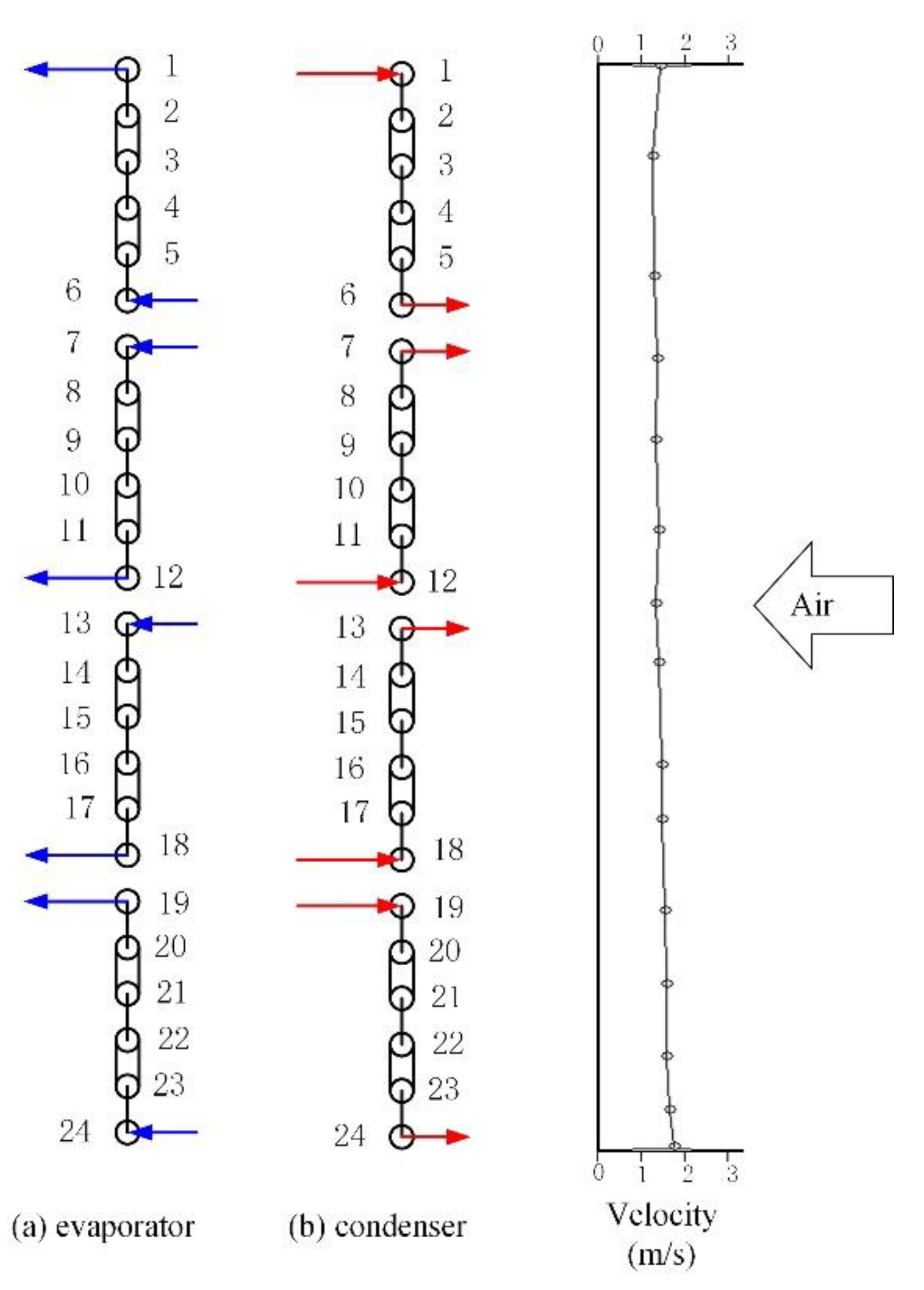
The heat transfer model for the outdoor FTHX was established in EVAP-COND 4.0 first. The arrangement of the coil and its interfacing with the airflow are schematically shown in Figure 2; the geometric parameters of the coil are very similar to the real ones. Note that the airflow onto the FTHX was actually two-dimensional, but the EVAP-COND series adopted a one-dimensional airflow. Therefore, the real air velocity was first experimentally measured over the whole FTHX and then integrated in the horizontal direction, as shown in Figure 2. Note that the non-uniformity of the airflow distribution was relatively mild due to the suction pattern of the airflow through the FTHX and the axial fan successively. Therefore, the four-circuit division of the FTHX was the same in the commercial prototype.
The equations to calculate the heat transfer coefficients and pressure drops for both sides were applied before the simulations. For the refrigerant side, the boiling and condensing heat transfer coefficients were obtained with the Thome [25] and Shah Equations [26], respectively, while the single-phase heat transfer coefficient was calculated with McAdams Equation [27]. The pressure drop equations for straight tubes and bends are different. In the tubes, single- and two-phase pressure drops are obtained with Blasius and Müller-Steinhagen Equations, respectively [28]. In the bends, by contrast, the single- and two-phase pressure drops are calculated with Chisholm [29] and Idelchik [30] Equations, respectively. For the air side, however, the pressure drop was not calculated by the software, and the heat transfer coefficient was obtained with Wang Equation [31].
The original outdoor FTHX in the ASHP was four-circuit reversely fixed, and its heat transfer performance in both condenser and evaporator modes were tested first for the optimization and validation of the simulations. The obtained constraint parameters for the FTHX simulations are listed in Table 3. Note that to improve the reliability of the evaporator simulations, the outlet quality of the evaporator was set to 0.98, which differed from the actual slightly superheated state, but this had a little effect on the overall capacity. All the heat transfer tubes were labelled with numbers, 1–24, from the top down, as shown in Figure 2.
Therefore, the experimental and numerical results of the heat transfer outputs in the condenser mode were compared to validate the accuracy of the simulations, as reported in Table 4. The condenser capacity was 3.85 kW in the simulation and 3.77 kW in the experiment, with a deviation of 2.1%. The tube temperatures in the simulation deviated from those in the experiment within 2 °C in most cases, except for Tubes 13, 16, 18 and 19. Tubes 18 and 19 were inlets of the bottom two circuits and tended to obtain more refrigerant because of gravity. Besides, the refrigerant flowed through a long tract to reach these two tubes in the vapor header and was cooled by the low-temperature ambience. Hence, Tubes 18 and 19 were cooler than Tubes 1 and 12 in the experiments. The lower temperature of Tube 18 propagated to Tubes 16 and 13, denoting that this circuit was overfed with respect to the others. However, the EVAP-COND software could hardly simulate the maldistribution of the refrigerant caused by gravity, so we observed a large deviation between the experimental and the numerical temperatures of these tubes. In general, the numerical and experimental results showed limited deviations in the condenser capacity and tube temperatures, thus validating the accuracy of the simulation.

4. Results and Discussion

4.1. Effect of the Circuit Number on the Evaporator and Condenser Performance

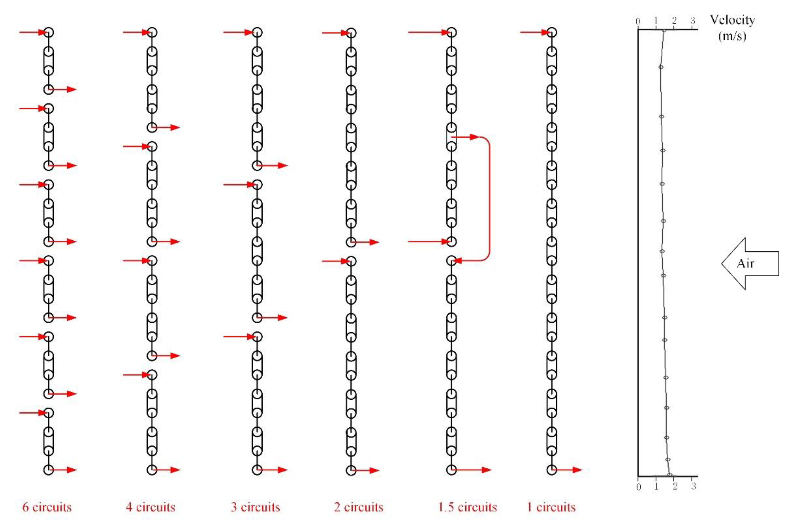
The effect of the circuit number on the FTHX performance was investigated for the evaporator and the condenser, respectively. Since there were in all 24 heat transfer tubes in the FTHX, one, two, three, four and six elementary circuits were naturally considered for the simulation, as shown in Figure 3. The constraint parameters for both the evaporator and the condenser simulations are listed in Table 2 and were obtained in experimental tests for the four-circuit reversely fixed FTHX in both heating and cooling cycles of the ASHP.
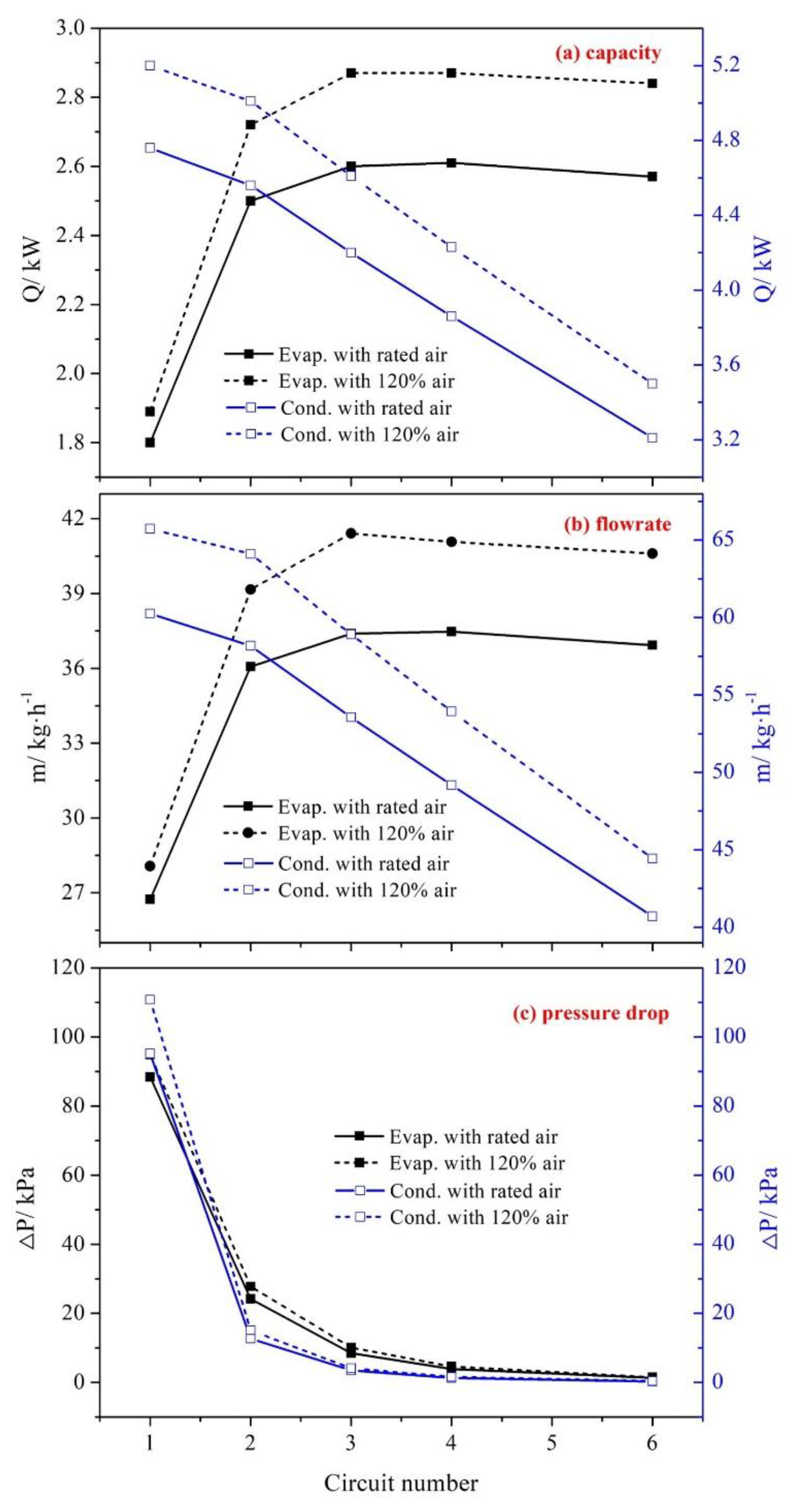
Figure 4 illustrates the variations of FTHX performance with the circuit number. The pressure drop decreased monotonously with the increase in the circuit number for both the evaporator and the condenser, since more circuits meant a lower velocity of the refrigerant. The variation in the capacity, however, differed between the two modes. The capacity of the evaporator increased first and then decreased, exhibiting the highest value of 2.61 kW with four circuits. The capacity of the condenser, by contrast, decreased monotonously from 4.76 kW to 3.21 kW as the circuit number increased from one to four. The variations of the refrigerant flowrate with the circuit number showed the same trend. Therefore, it was deduced that more circuits are preferable in the evaporator, while in the condenser fewer are better, which is consistent with the observations in Ref. [8]. In fact, the FTHX performance under 120% rated air flowrate was also studied and showed a similar trend as that with rated air, as also shown in Figure 4, which confirmed that more circuits were a better option for the evaporator, while fewer circuits were best for the condenser.
The tube capacity is a product of heat transfer area, overall heat transfer coefficient and temperature difference. The tube capacity is read directly in the EVAP-COND 4.0 software. The temperature difference in this article was determined as the logarithmic mean value calculated from the refrigerant inlet, refrigerant outlet, air inlet and air outlet temperatures. Then, the overall heat transfer coefficient for each tube was obtained by dividing the tube capacity by its outer surface area and the temperature difference.
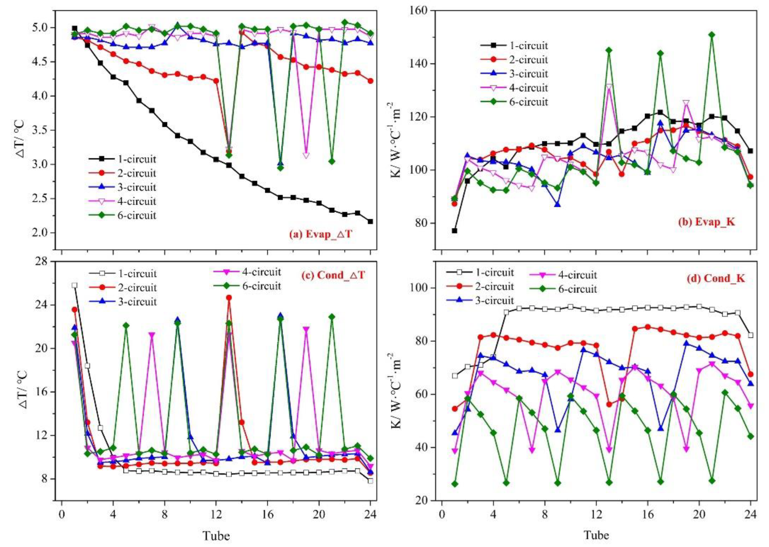
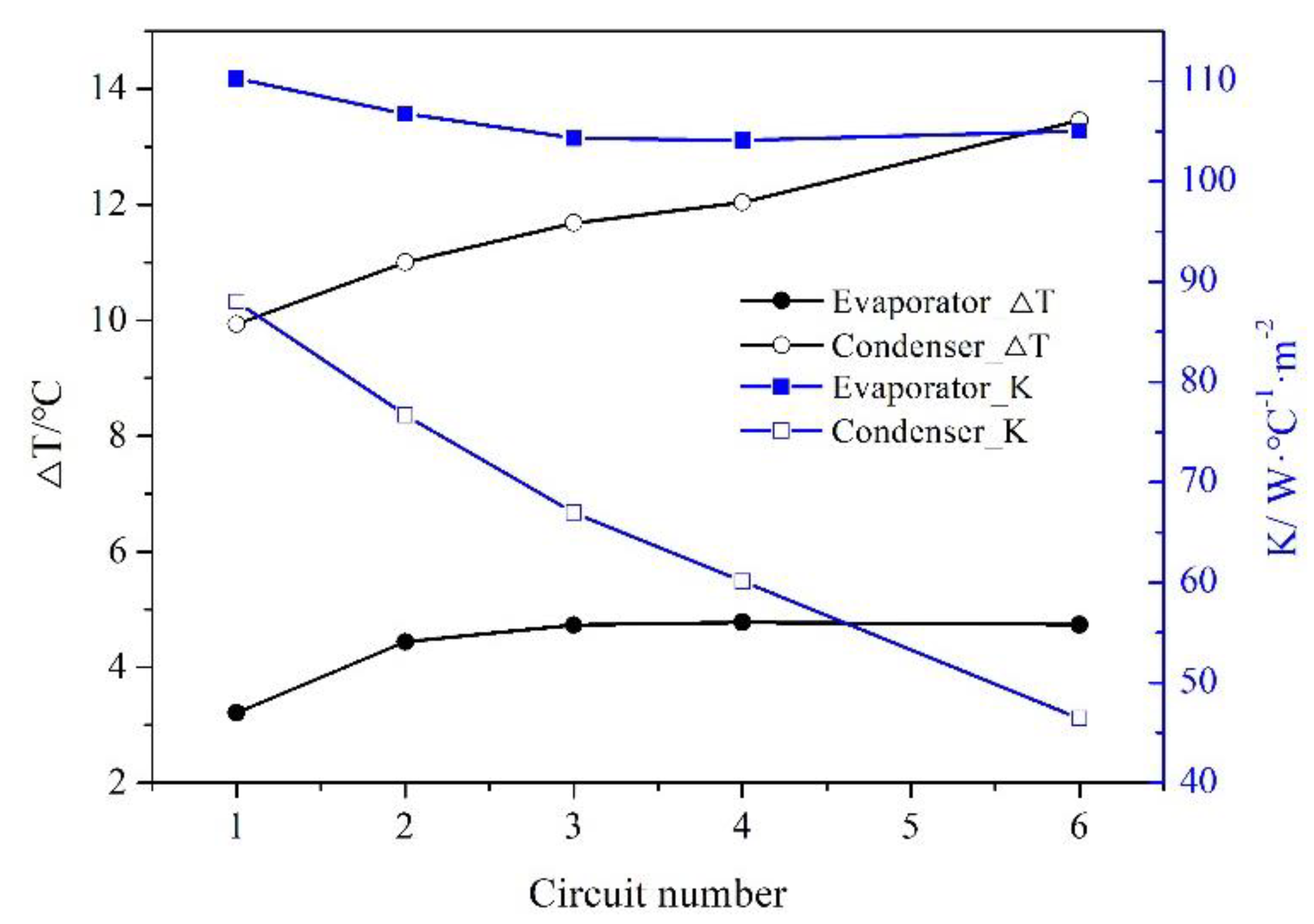
Figure 5 shows the tube-by-tube distribution of the overall heat transfer and temperature differences in the FTHX, which corresponded strongly to the circuit division. In addition, for both the evaporator and the condenser, the overall heat transfer coefficient generally decreased, but the temperature difference increased as the circuit number increased.
Figure 6 presents the average values of the overall heat transfer coefficient and temperature differences for all 24 tubes in the FTHX. In general, the overall heat transfer coefficient decreased with as the circuit number increased, since more circuits led to a lower refrigerant velocity and a smaller refrigerant-side heat transfer coefficient. The temperature difference increases with the circuit number, because a lower refrigerant velocity also led to a smaller pressure drop (also shown in Figure 4) and further reduced the corresponding temperature drop in the liquid–vapor two-phase area. For the same heat transfer area, therefore, the FTHX capacity was determined by the trade-off between the overall heat transfer coefficient and the temperature difference.
For the evaporator, the capacity increased first and then decreased, indicating that the increase in temperature difference overwhelmed the decrease in overall heat transfer coefficient with one to four circuits, but the opposite occurred with four to six circuits. For the condenser, however, the capacity decreased monotonously, denoting that the decrease in overall heat transfer coefficient was always the dominant factor. Figure 4 shows that as the circuit number increased from one to four, the overall heat transfer coefficient was reduced by only 4.8% in the evaporator mode but by 47.2% in the condenser mode. This dramatic difference resulted from the fact that the refrigerant flowrate in the FTHX generally increased in the evaporator mode but decreased remarkably in the condenser mode, as shown in Figure 4.
In short, the evaporator exhibited the highest capacity with four circuits because of the trade-off between the decreased overall heat transfer coefficient and the increased temperature difference. The condenser, however, showed a monotonously reduced capacity, since the overall heat transfer decreased greatly and always dominated the capacity decrease as the circuit number increased. Therefore, this contradiction caused a difference in the optimal number of circuits for the evaporator and the condenser. Next, we demonstrated that the reversely variable circuitry in the FTHX could address this problem.

4.2. Reversely Variable Circuitry

Based on the above analysis, the ideal circuitry of the FTHX should change the refrigerant flowpath between the evaporator and condenser modes flexibly, so that:
(i)
the evaporator will hold four parallel circuits
(ii)
the condenser will exhibit as few circuits as possible
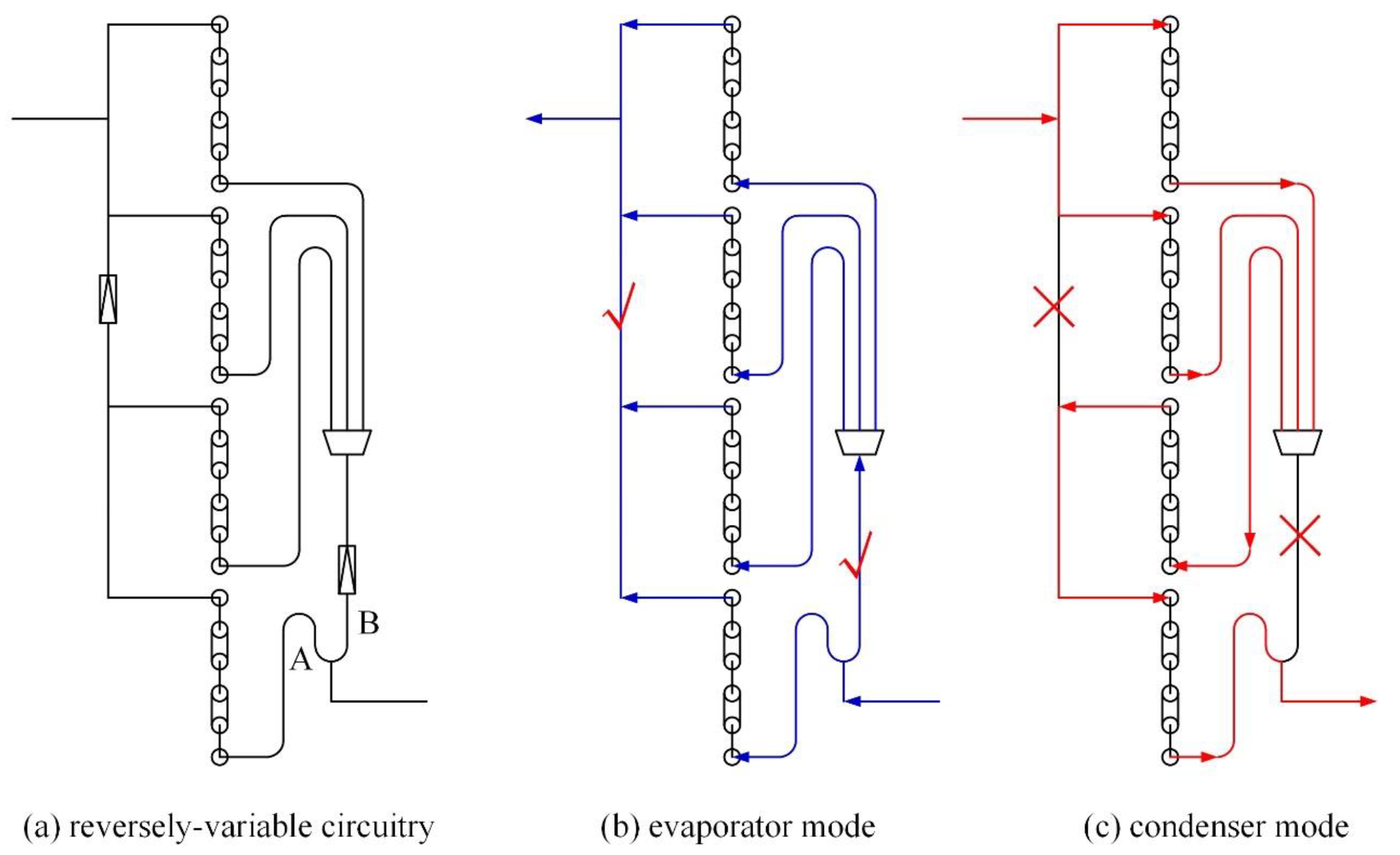
Therefore, the reversely variable circuitry was realized with two single-way valves and two distributors, as conceptually shown in Figure 6. The entire FTHX was divided into four elementary circuits with two distinct features. First, the FTHX was fed with a two-branch distributor and a three-branch distributor successively, rather than a four-branch one directly. Second, two single-way valves were added, one inside the vapor header, and the other between the two distributors. In this way, the FTHX exhibited four parallel circuits in the evaporator mode but 1.5 circuits (two circuits merging into one) in the condenser mode, as illustrated in Figure 7.
The optimal flowpath for the FTHX in the condenser mode is the single-circuit one. However, the reverselyvariable circuitry with two single-way valves could achieve the 1.5-circuit flowpath at the least, similar to the single-circuit one in terms of heat transfer performance, as also illustrated in Figure 3. With three or more single-way valves, the single-circuit flowpath should be obtained in the reversely variable circuitry. However, that will also result in additional problems such as higher pressure drops and costs and is not suitable for other applications.
It should be noted that the two-distributor scheme might lead to non-uniform feeding among the four circuits. In the evaporator mode, Branch B of the two-branch distributor should supply the refrigerant to the upper three circuits, while Branch A should distribute it only to the bottom one, as indicated in Figure 6. Hence, the parameters of the branch tubes and the manifold should be adjusted in the rated heating conditions. The diameters of Branch A, Branch B and the manifold were 3.36 mm, 5.6 mm and 8.12 mm, respectively. The length of the two branch tubes was also carefully modified. In this way, approximate uniform feeding was achieved for the four parallel circuits in the rated heating conditions.

4.3. Comparison between Reversely Variable and Reversely Fixed FTHXs

Then, the reversely variable FTHX was tested in the ASHP and compared with a reversely fixed FTHX. Figure 6 shows that the reversely variable FTHX exhibited four circuits in the evaporator mode but 1.5 in the condenser mode. Hence, two types of reversely fixed FTHXs were taken into consideration, i.e., the four-circuit one and the 1.5-circuit one.
For an easy execution of the comparative tests, the single-way valves in Figure 6 were actually replaced with check valves, and the three circuitries could be obtained with different on/off schemes of the two check valves, as reported in Table 5. The four-circuit configuration of the FTHX was realized with both check valve always open, while the 1.5-circuit was built with the two check valves always closed. The variable circuitry, however, was obtained with the two check valves open in the evaporator mode but closed in the condenser mode. Moreover, for easy installation and uniform feeding, the four parallel circuits of the FTHX in the reversely variable circuitry were modified slightly, as shown in Figure 6. The top two inlets in the evaporator mode were close to each other, and the bottom two outlets were connected together with a T-junction. Then, the FTHXs in the three schemes were tested in both heating and cooling conditions.
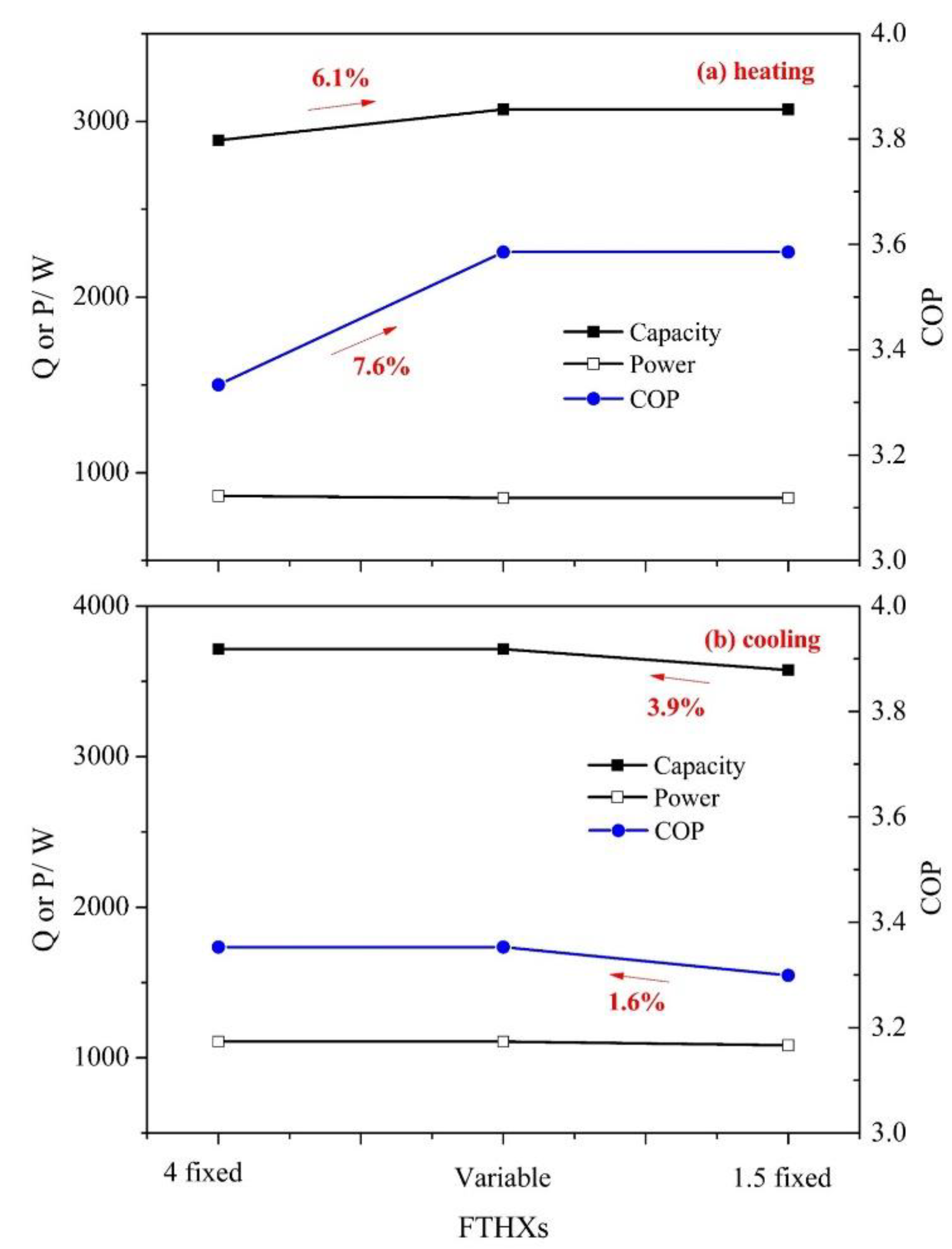
Figure 8 illustrates the energy outputs of the ASHP with the above three FTHXs. Note that the four-circuit reversely fixed configuration was obtained with both check valves always open in the prototype; the heating outputs of the four -circuit reversely fixed FTHX were actually the same as that of the reversely variable one in Figure 7. Similarly, the cooling outputs of the 1.5-circuit reversely fixed FTHX were also the same as those of the reversely variable one.
Figure 8 indicates that the reversely variable circuitry had better overall performance compared to the other two. In the rated cooling conditions, the reversely variable FTHX resulted in 6.1% higher capacity and 7.6% higher COP of the ASHP than the four-circuit reversely fixed one. In the rated heating conditions, by contrast, the reversely variable FTHX resulted in about a 3.9% larger capacity and a 1.6% larger COP of the ASHP than the 1.5-circuit reversely fixed FTHX. That is to say, the reversely variable FTHX enhanced both the heating and the cooling performance of the ASHP.
In short, the reversely variable circuitry allowed different flowpaths for the refrigerant in evaporator and condenser modes, thus better matching their respective requirements by varying the circuit number. The condenser with fewer circuits enhanced the overall heat transfer coefficient and promoted the capacity increase of the outdoor FTHX. The evaporator with more circuits reached a balance between the overall heat transfer coefficient and the temperature difference, finally increasing the capacity of the outdoor FTHX on the basis of this trade-off. Consequently, the overall energy performance of the ASHP was enhanced in both heating and cooling conditions.

5. Conclusions

In this article, a reversely variable circuitry was proposed for an outdoor FTHX in an ASHP to enhance its overall energy performance. The effect of the circuit number on the FTHX performance in both evaporator and condenser modes was studied numerically, so as to find the optimal circuit number for either mode. The reversely variable circuitry was then proposed conceptually for the FTHX to change the refrigerant flowpath in different direction and satisfied the contrasting requirements as regards the circuit number of the evaporator and the condenser. Finally, the reversely variable FTHXs were compared with the reversely fixed ones experimentally, showing the energy-saving potential of the formers. Our detailed conclusions are as follows.
(1)
The evaporator capacity first increased and then decreased as the circuit number increased, exhibiting the highest 2.61 kW with the optimal four-circuit scheme due to the trade-off between reduced overall heat transfer coefficient and increased temperature difference.
(2)
The condenser capacity decreased monotonously from 4.76 kW to 3.21 kW as the circuit number increased from one to six, because of the greatly reduced overall heat transfer coefficient.
(3)
The reversely variable circuitry was achieved with the combination of single-way valves and distributors, and exhibited four circuits in the evaporator mode and 1.5 circuits in the condenser mode, so as to better satisfy the respective needs in circuit number for both modes.
(4)
The reversely variable FTHX led to a better overall energy performance of the ASHP, with a 6.1% higher heating capacity than the four-circuit reversely fixed FTHX and a 3.9% larger cooling capacity than the 1.5-circuit FTHX.

Author Contributions

Conceptualization, D.H. and F.W.; Methodology, R.Z.; Software, R.Z.; Validation, Y.S. and Z.W.; Formal analysis, R.Z.; Investigation, R.Z., F.W. and Y.S.; Resources, D.H. and F.W.; Data curation, Z.W. and Y.S.; Writing—original draft preparation, R.Z.; Writing—review and editing, Z.W. and Y.S.; Supervision, D.H.; Project administration, F.W.; Funding acquisition, R.Z. and D.H. All authors have read and agreed to the published version of the manuscript.

Funding

The present work was supported by the National Natural Science Foundation of China (No. 51806161) and Major Science and technology innovation engineering projects of Shandong Province (No. 2019JZZY020813).

Institutional Review Board Statement

Not applicable.

Informed Consent Statement

Not applicable.

Data Availability Statement

Not applicable.

Conflicts of Interest

The authors declare no conflict of interest.

References

  1. Sadeghianjahromi, A.; Wang, C. Heat transfer enhancement in fin-and-tube heat exchangers—A review on different mechanisms, Renew. Sust. Energ. Rev. 2021, 137, 110470. [Google Scholar] [CrossRef]
  2. Zhang, G.; Wang, B.; Li, X.; Shi, W.; Cao, Y. Review of experimentation and modeling of heat and mass transfer performance of fin-and-tube heat exchangers with dehumidification. Appl. Therm. Eng. 2019, 146, 701–717. [Google Scholar] [CrossRef]
  3. Bilen, K.; Cetin, M.; Gul, H.; Balta, T. The investigation of groove geometry effect on heat transfer for internally grooved tubes. Appl. Therm. Eng. 2009, 29, 753–761. [Google Scholar] [CrossRef]
  4. Andrade, F.; Moita, A.S.; Nikulin, A.; Moreira, A.L.N.; Santos, H. Experimental investigation on heat transfer and pressure drop of internal flow in corrugated tubes. Int. J. Heat Mass Transf. 2019, 140, 940–955. [Google Scholar] [CrossRef]
  5. Wang, Y.; Zhang, J.; Ma, Z. Experimental determination of single-phase pressure drop and heat transfer in a horizontal internal helically-finned tube. Int. J. Heat Mass Transf. 2017, 104, 240–246. [Google Scholar] [CrossRef]
  6. Siddique, M.; Alhazmy, M. Experimental study of turbulent single-phase flow and heat transfer inside a micro-finned tube. Int. J. Refrig. 2008, 31, 234–241. [Google Scholar] [CrossRef]
  7. Li, G.; Huang, L.; Tao, L. Experimental investigation of refrigerant condensation heat transfer characteristics in the horizontal microfin tubes. Appl. Therm. Eng. 2017, 123, 1484–1493. [Google Scholar] [CrossRef]
  8. Huang, D.; Zhao, R.; Liu, Y.; Yi, D. Effect of fin types of fan-supplied finned-tube heat exchanger on periodic frosting and defrosting performance of a residential air-source heat pump. Appl. Therm. Eng. 2014, 69, 251–260. [Google Scholar] [CrossRef]
  9. Liu, X.; Wang, M.; Liu, H.; Qian, S. Numerical analysis on heat transfer enhancement of wavy fin-tube heat exchangers for air-conditioning applications. Appl. Therm. Eng. 2021, 199, 117597. [Google Scholar] [CrossRef]
  10. Sarfraz, O.; Bach, C.K.; Bradshaw, C.R. Reduced order modeling for multi-circuit fin-and-tube heat exchangers with multiple identical circuit types. Int. J. Refrig. 2019, 106, 236–247. [Google Scholar] [CrossRef]
  11. Abu-Hamdeh, N.H.; Bantan, R.A.R.; Alimoradi, A. Heat transfer optimization through new form of pin type of finned tube heat exchangers using the exergy and energy analysis. Int. J. Refrig. 2020, 117, 12–22. [Google Scholar] [CrossRef]
  12. Guo, K.; Zhang, N.; Smith, R. Design optimisation of multi-stream plate fin heat exchangers with multiple fin types. Appl. Therm. Eng. 2018, 131, 30–40. [Google Scholar] [CrossRef]
  13. Sinha, A.; Chattopadhyay, H.; Lyengar, A.K.; Biswas, G. Enhancement of heat transfer in a fin-tube heat exchanger using rectangular winglet type vortex generators. Int. J. Heat Mass Transf. 2016, 101, 667–681. [Google Scholar] [CrossRef]
  14. Liang, S.; Wong, T.N.; Nathan, G.K. Numerical and experimental studies of refrigerant circuitry of evaporator coils. Int. J. Refrig. 2001, 24, 823–833. [Google Scholar] [CrossRef]
  15. Huang, D.; Chen, Q.; Yuan, X. Effect of circuit number on the indoor coil serving as both condenser and evaporator in heat pump. J. Xi’an Jiaotong Univ. 2007, 41, 543–548. (In Chinese) [Google Scholar]
  16. Bahman, A.M.; Groll, E.A. Application of interleaved circuitry to improve evaporator effectiveness and COP of a packaged AC system. Int. J. Refrig. 2017, 79, 114–129. [Google Scholar] [CrossRef]
  17. Saleem, S.; Bradshaw, C.R.; Bach, C.K. Validation of a multi-circuit heat exchanger model for evaluating the effect of refrigerant circuitry on cross-fin conduction in evaporator mode. Int. J. Refrig. 2021, 131, 623–633. [Google Scholar] [CrossRef]
  18. Yashar, D.A.; Lee, S.; Domanski, P.A. Rooftop air-conditioning unit performance improvement using refrigerant circuitry optimization. Appl. Therm. Eng. 2015, 83, 81–87. [Google Scholar] [CrossRef]
  19. Ishaque, S.; Kim, M.H. Numerical modeling of an outdoor unit heat exchanger for residential heat pump systems with nonuniform airflow and refrigerant distribution. Int. J. Heat Mass Transf. 2021, 175, 121323. [Google Scholar] [CrossRef]
  20. Sim, J.; Lee, H.; Jeong, J.H. Optimal design of variable-path heat exchanger for energy efficiency improvement of air-source heat pump system. Appl. Energ. 2021, 290, 116741. [Google Scholar] [CrossRef]
  21. Wang, F.; Zhao, R.; Ma, C.; Huang, D.; Qu, Z. Reversely-variable circuitry for finned-tube heat exchanger in air source heat pump to enhance its overall energy performance. Int. J. Refrig. 2022, 142, 48–57. [Google Scholar] [CrossRef]
  22. Moffat, R.J. Describing the uncertainties in experimental results. Exp. Therm. Fluid Sci. 1998, 1, 3–17. [Google Scholar] [CrossRef]
  23. Domanski, P.A. Simulation of an evaporator with nonuniform one-dimensional air distribution. ASHRAE Trans. 1991, 97, 793–802. [Google Scholar]
  24. Song, X.; Huang, D.; Liu, X.; Chen, Q. Effect of non-uniform air velocity distribution on evaporator performance and its improvement on a residential air conditioner. Appl. Therm. Eng. 2012, 40, 284–293. [Google Scholar] [CrossRef]
  25. Thome, J.R. Update on advances in flow pattern based two-phase heat transfer models. Exp. Therm. Fluid Sci. 2005, 29, 341–349. [Google Scholar] [CrossRef]
  26. Shah, M.M. General correlation for heat transfer during film condensation inside pipes. Int. J. Heat Mass Transf. 1979, 22, 547–556. [Google Scholar] [CrossRef]
  27. ASHRAE. ASHRAE Handbook: Fundamentals Volume; American Society of Heating, Refrigerating and Air Conditioning Engineers, Inc.: Atlanta, GA, USA, 2001; pp. 3–14. [Google Scholar]
  28. Müller-Steinhagen, H.; Heck, H.K. A simple friction pressure drop correlation for two-phase flow in pipes. Chem. Eng. Process 1986, 20, 297–308. [Google Scholar] [CrossRef]
  29. Chisholm, D. Two-Phase Flow in Pipelines and Heat Exchangers; George Godwin: London, UK, 1983; pp. 304–305. [Google Scholar]
  30. Idelchik, I.E. Handbook of Hydraulic Resistance, 2nd ed.; Hemisphere: New York, NY, USA, 1986; pp. 640–641. [Google Scholar]
  31. Wang, C.C.; Jang, J.Y.; Chiou, N.F. A heat transfer and friction correlation for wavy fin-and-tube heat exchangers. Int. J. Heat Mass Transf. 1999, 42, 1919–1924. [Google Scholar] [CrossRef]
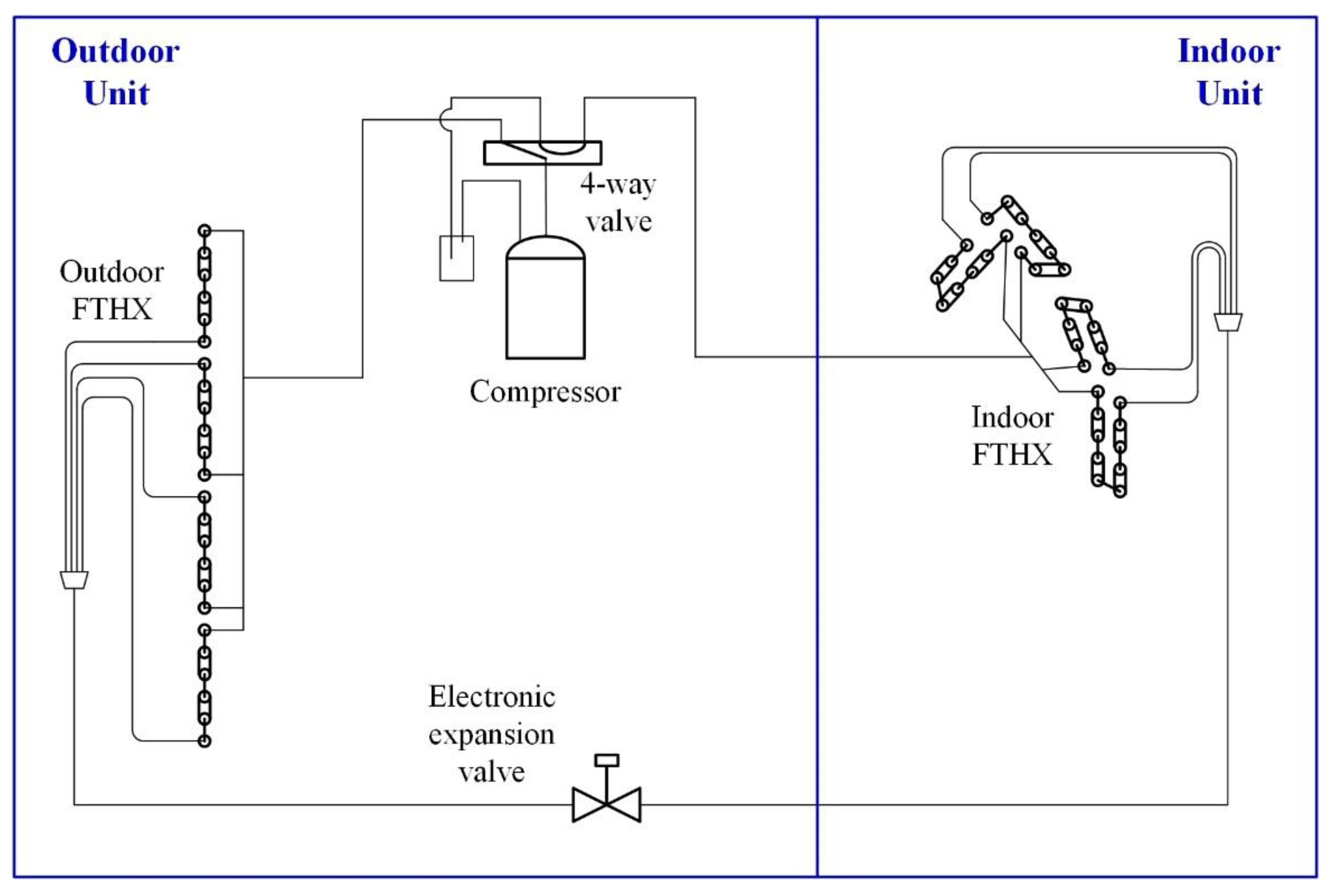
Figure 1. Schematic diagram of the tested ASHP [21].
Applsci 12 08960 g001
Figure 2. Schematic diagram of the FTHX and airflow arrangement in EVAP-COND.
Applsci 12 08960 g002
Figure 3. Elementary circuit options for the outdoor FTHX.
Applsci 12 08960 g003
Figure 4. Effect of the circuit number on FTHX performance.
Applsci 12 08960 g004
Figure 5. Tube-by-tube overall heat transfer coefficients and temperature differences in the FTHX.
Applsci 12 08960 g005
Figure 6. Overall heat transfer coefficient and temperature difference with a different number of circuits.
Applsci 12 08960 g006
Figure 7. Conceptual diagram of the reversely variable circuitry.
Applsci 12 08960 g007
Figure 8. Energy outputs for the AHSP with three types of FTHXs.
Applsci 12 08960 g008
Table 1. Parameters and specifications of the ASHP components.
ItemInformation
Indoor coilTube number34, 18 in the 1st row and 16 in the 2nd row
Outer diameter5 mm
Tube length630 mm
Fin pitch1.4 mm
Outdoor coilTube number24 in one row
Outer diameter7 mm
Tube length770 mm
Fin pitch1.25 mm
Electronic expansion valveDunAn DPF1.3C-B059
CompressorGSD098CKQA6JT6B
RefrigerantR32 with 570 g charge
Table 2. Conditions and control parameters of the tested ASHP.
ConditionsOutdoor Temp. (Dry/Wet Bulb)Indoor Temp. (Dry/Wet Bulb)Compressor SpeedEEV Target Discharge Temp.Out FTHX
Air Flowrate
Rated cooling35/24 °C27/19 °C55 Hz79 °C1800 m3/h
Rated heating7/6 °C20/15 °C90 Hz73 °C2400 m3/h
Table 3. Constraint parameters for the FTHX simulations.
ModesCondenserEvaporator
RefrigerantInlet temperature/°C48.5Outlet sat. temperature/°C0.8
Inlet superheat/°C34.8Outlet quality0.98
Subcooling/°C1.3Inlet quality0.15
AirAir inlet temperature/°C35Air inlet temperature/°C7
Air inlet pressure/MPa0.101Air inlet pressure/MPa0.101
Air inlet relative humidity0.40Air inlet relative humidity0.86
Table 4. Numerical and experimental results of the condenser performance for the two FTHXs.
TubeExperimentalNumericalDeviation
181.9 °C83.3 °C+1.4 °C
1284.0 °C83.3 °C−0.7 °C
1875.5 °C83.3 °C+7.8 °C
1978.5 °C83.3 °C+4.8 °C
347.7 °C48.5 °C+0.8 °C
1047.8 °C48.5 °C+0.7 °C
1641.7 °C48.5 °C+6.8 °C
2147.6 °C48.5 °C+0.9 °C
646.2 °C48.5 °C+2.3 °C
743.7 °C47.1 °C+3.4 °C
1337.0 °C46.5 °C+9.5 °C
2447.0 °C45.6 °C−1.4 °C
Capacity3.77 kW3.85 kW+2.1%
Table 5. On/off scheme of the check valves in different modes of the FTHX.
ModesEvaporatorCondenser
Prototype Applsci 12 08960 i001
VariableOnOff
4-circuit fixedOnOn
1.5-circuit fixedOffOff
Publisher’s Note: MDPI stays neutral with regard to jurisdictional claims in published maps and institutional affiliations.