Abstract
High-sensitivity ac current sensors based on a superconducting quantum interference device have been designed, fabricated and characterized. In particular, double-washer schemes in either parallel or series configurations have been considered. The advantages and the drawbacks of both configurations have been examined by measuring the main features and parameters, such as the flux-to-voltage characteristic, the magnetic field spectral noise and flux-to-current transfer factor. The devices are designed to have similar flux-to-current transfer factors and are fabricated on the same chip to avoid differences in parameters due to the fabrication process. Both devices exhibited a current sensitivity as low as 1–2 pA per bandwidth unit, allowing for their use in ultrahigh-sensitivity applications.
1. Introduction
Recently, great efforts have been devoted to the development of ultrasensitive magnetic sensors, as they allow for the realization of high-sensitivity applications and the carrying out of fundamental physics experiments of great interest [1].
Magnetic sensors that are particularly interesting and promising in terms of performances are the hybrid magnetometer, based on giant magnetoresistance spin valves [2]; the atomic magnetometer, based on detection of the Larmor spin precession of optically pumped atoms [3]; and the diamond magnetometer, based on nitrogen-vacancy centers in room-temperature diamond [4].
However, magnetic sensors based on superconducting quantum interference devices (SQUIDs) are still a powerful tool due to their extreme sensitivity together with great versatility, despite the principle of operation being discovered more than 50 years ago. For instance, nanoSQUID development currently attracts great interest since their ultrahigh magnetic moment sensitivity, reaching a few Bohr magnetons per unit of bandwidth, allows for the measurement of direct magnetization changes in small spin systems [5].
SQUID sensitivity is limited only by the fundamental principles of quantum mechanics, i.e., by Heisenberg’s uncertainty principle. In fact, they are able to reach a sensitivity in energy per bandwidth unit equal to a few Planck constants [6]. This extreme sensitivity is essentially due to the properties of the superconductors, which represent the most spectacular evidence of quantum mechanics at the macroscopic level. A SQUID consists of a superconducting ring interrupted by two Josephson junctions (two superconductors separated by a very thin insulating barrier). Therefore, their principle of operation is based on two typical effects of superconductivity, namely the Josephson effect and the quantization of the flux inside a superconducting ring [7]. The Josephson effect is the tunneling of Cooper pairs through a thin insulator barrier (1–2 nm) between two superconductors, while the flux quantization states that the magnetic flux through a superconducting ring cannot have arbitrary values, but is a multiple of an elementary magnetic flux equal to Φ0 = h/2e = 2.07 × 10⁻¹⁵ Wb, where h is the Plank constant and e is the electron charge [8,9]. Beyond the physical–mathematical formalism underlying the operation of a SQUID sensor, we can say that it is a magnetic flux–voltage transducer. In fact, if a SQUID is placed in a magnetic field and biased with a direct current just above twice the individual Josephson junction critical current, an oscillating voltage is observed across the sensor, whose period of oscillation is equal to Φ0. Therefore, by measuring the voltage across the sensor and knowing the voltage responsivity VΦ = ∂V/∂Φ, it is possible to obtain the value of the magnetic field. Obviously, a magnetic sensor, in addition to the flux and the magnetic field, can measure everything that can be converted into a magnetic field or flux, such as a current, a voltage, a displacement, etc.
The design of a SQUID sensor strongly depends on the type of measurement it will have to carry out [10]. Due to their great sensitivity, SQUID sensors typically operate in a shielded environment; however, it is possible to use particular configurations called gradiometric configurations that allow the use of these sensors even in moderately or poorly shielded environments [11].
In this article, we report experimental results concerning the development of SQUID current sensors in which the superconducting ring has a gradiometric configuration of both series and parallel type. These devices can be used to develop ultrasensitive ammeters or magnetometers and gradiometers by connecting them via superconducting soldering to external superconducting coils.
In the second paragraph, the adopted criteria for the device design together with the fabrication process and experimental setup will be described. In the third paragraph, we will show the experimental data concerning the characterization at low temperatures and the relative comparisons between the two different configurations.
2. Design, Fabrication and Experimental Setup
SQUID sensors based on gradiometric design allow for a high current sensitivity to be obtained thanks to high mutual inductance M between the SQUID and input coil, at the same time keeping a high rejection factor to the ambient noise. There are different gradiometric designs: parallel or series configurations of first and higher order and combinations of series and parallel configurations [7,10]. The parallel configuration can ensure relatively low inductance, while the series one has the advantage to completely cancel the screening current everywhere in common mode excitation [12].
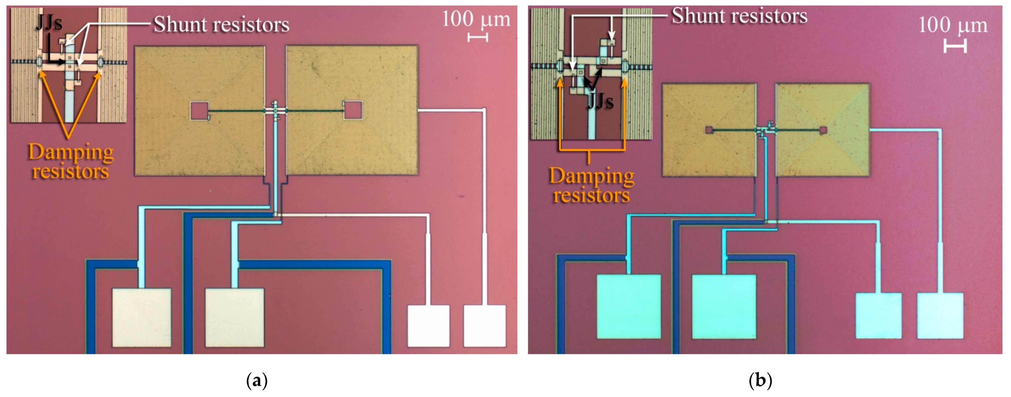
The design of both gradiometers in parallel and series configurations is based on a double-washer-shaped SQUID ring inductively coupled to the underlying multiturn input coils [13]. In Figure 1, the pictures of the realized device are reported; in the parallel configuration, the two washer sections are connected in a parallel way, leading to a total inductance Lp = Lw/2, while in the series connection, the total inductance is Ls = 2 Lw, where Lw is the inductance of a single washer. Both the input coils are wound so that the input current circulates in the same direction, generating two concordant magnetic fluxes.
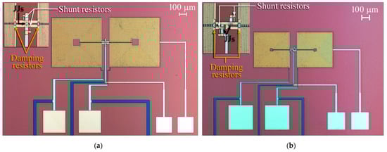
Figure 1.
Picture of SQUID-based current gradiometric sensors. (a) Parallel configuration, (b) series configuration. In the respective insets, a magnification of area including Josephson junctions, damping and shunt resistors of both devices are shown and indicated by an arrow.
A key factor for a SQUID current sensor consists of transfer factor between the input current and the magnetic flux (IΦ), often known as current sensitivity and given by the reciprocal of the mutual inductance M as defined above; it represents the current flowing in the signal coil that induces one flux quantum Φ0 into the SQUID loop.
We chose to design the SQUID sensor with a similar flux-to-current transfer factor, taking into account that too high an inductance value could led to performance degradation in the series configuration [14].
In a single-washer-shaped SQUID, its geometrical inductance, neglecting the parasitic inductance of the interconnection of the washer to the junctions (typically a few pH) [15], can be obtained by summing the inductances of the washer and the slit [12]:
where d is the washer hole inner dimension and bT is the slit length. Referring to a single washer, in the case of parallel configuration, the hole dimension measures 100 µm while the slit length is 404 µm; and in the series case, the hole and slit length are 35 µm and 290 µm, respectively. Both input coils consist of a series of 2 multiturn windings having NP = 40 and NS = 29 turns and being magnetically coupled to the SQUID in double-washer configuration. Their inductances can be calculated as [12]:
where N is the turn number of input coil; while Lh and Lsl are the inductance of the washer hole and slit, respectively. represents the stripline inductance for unit length and ℓ is the total length of the input coil winding. depends on the stripline geometry and the London penetration depth. In this case, this inductance contribution affects the total inductance for a few nH.
The mutual inductance between the input coil and the double-washer SQUID can be computed by using the following equations:
In the Table 1, the main geometric features of the devices are summarized and electrical parameters are computed.

Table 1.
Main geometrical and electrical parameters of current sensor devices.
A high intrinsic responsivity of SQUID (VΦ = ∂V/∂Φ ∝ I0Rs) was obtained by increasing the critical current density of the Josephson junctions rather than the shunt resistor value to limit the increase in McCumber parameter:
which has a quadratic dependence on the resistance, which can give rise to hysteresis phenomena in the current–voltage characteristics [16]. Here, Cj is the junction capacitance, 2 I0 is the SQUID critical current, Rs is the shunt resistor and Φ0 the magnetic flux quantum. To avoid performance degradation due to a nonoptimal inductance parameter βL = 2 LI0/Φ0, a damping resistor equal to the junction shunt resistor across each SQUID washer was inserted (Figure 1) [17].
The fabrication process was extensively described elsewhere [18] and is only briefly summarized below. The process is based on so-called trilayer technique, in which in an ultrahigh-vacuum system, a multilayer structure consisting of Nb/Al-AlOx/Nb is deposited by dc sputtering without vacuum break on a silicon substrate patterned by optical photolithography to define the sample geometry. At this step, the tunnel barrier is obtained by filling the chamber by dry oxygen after the aluminum deposition. A lift-off process completes this first stage. The Josephson junctions, having a square shape with an area of 4 × 4 µm2 each one, are patterned again by optical photolithography and achieved via selective niobium anodization process (SNAP) of top niobium. A further insulation layer of silicon dioxide deposited by rf sputtering enhances the insulation, especially on the junction edges. The shunt and damping resistors of the SQUID are made by depositing a layer of Au-Pd alloy by dc sputtering in a second UHV system. In the same system equipped with an ion gun, after a last photolithography step to define the geometry of the device wiring, a thicker layer (500 nm) of Nb film is deposited once again by dc sputtering aftera preliminary cleaning of the surface oxide using the ion gun.
The complete characterization of the sensors, including measurements of the voltage (V)–magnetic flux (F), the input current–magnetic flux transfer factor and the spectral density of magnetic flux noise, were performed in a liquid helium bath at T = 4.2 K by using a cryogenic insert equipped with a coaxial lead–cryoperm double cylinder for high shielding to magnetic disturbances. A copper box for radiofrequency shielding, held at room temperature, contains the readout electronics, which due to intrinsic high-voltage swing of the sensors, can be directly coupled to an ultralow-noise amplifier. The voltage noise spectral density of the amplifier used for the following SQUID characterization is 0.7 nV/Hz1/2.
3. Results and Discussion
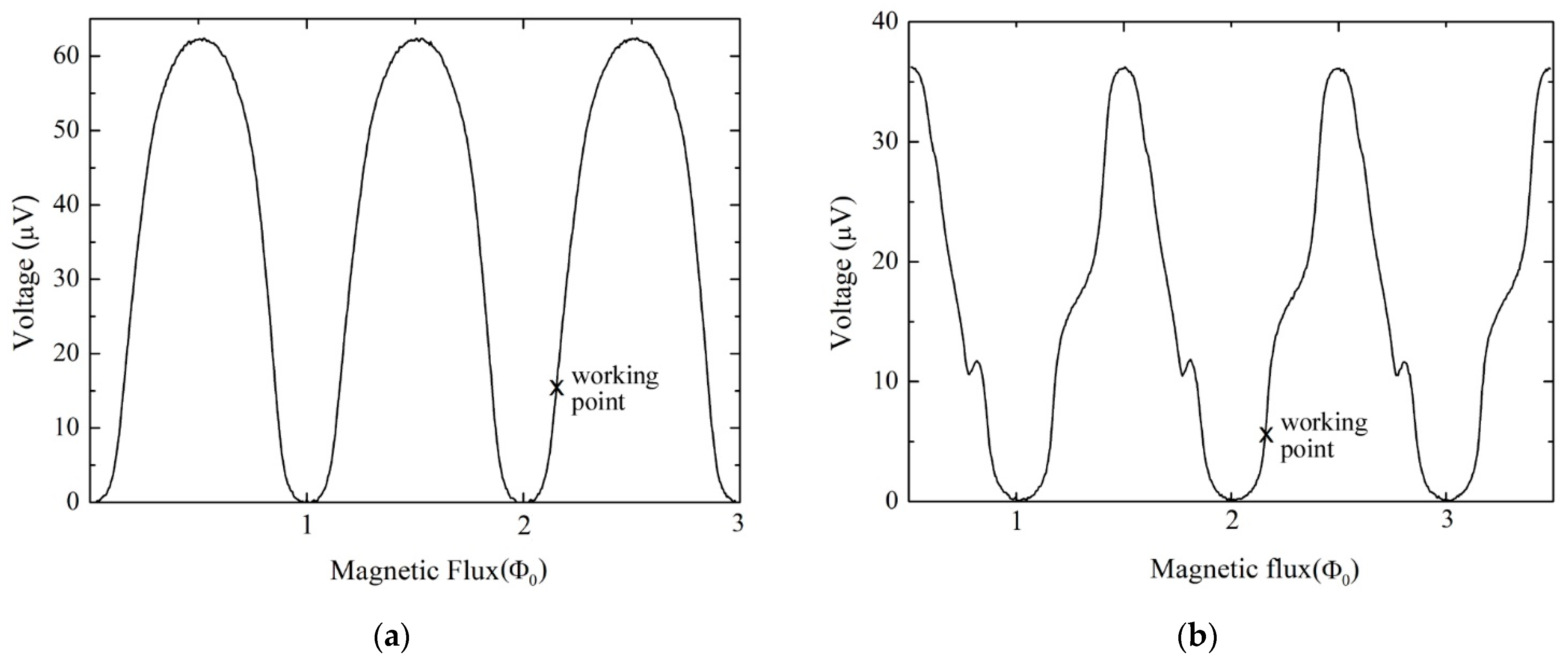
Both devices are based on SQUID, including two Josephson junctions having an area of 16 µm2 each and whose capacitance is Cj = 1.3 pF. The SQUID shunt resistors are Rs = 3 Ω, and the same value was used for damping one. As expected, the SQUID critical currents are very similar, resulting in Ic,P = 24.6 µA in parallel configuration, while Ic,S = 26.4 µA in the series case. In Figure 2, the magnetic flux vs. voltage characteristics of both devices are reported. The bias currents that maximize the curves are 26 μA and 28 μA for the parallel and series configuration, respectively. The maximum intrinsic responsivities, as results from the slope of V-Φ curves, are VΦ = 350 µV/Φ0 and VΦ = 290 µV/Φ0, respectively. The smaller value of voltage swings in the series case is due to a larger SQUID inductance parameter βL, since its inductance is significantly higher than the parallel configuration, with βL,S = 6.75 while βL,P = 3.3. Note that for the series gradiometer, the washer size has to be reduced to avoid too high an inductance. Therefore, for a minimum patterning pitch of the input coil, this reduced washer size leads to a smaller number of input turns per washer compared to the larger washer of the parallel design. Some evident distortions appear on the V-Φ characteristic of the series configuration type (Figure 2b). This is probably caused by the feedback effect due to a parasitic capacitance between the input coil and the ground of the SQUID [19,20] or even due to the stripline resonance of the input coil whose resonance frequency, inversely proportional to the length of the input coil, could fall in the operative range. However, this condition, despite a slight device instability, produces an increase in intrinsic responsivity that can be exploited, choosing a suitable working point [21]. As mentioned above, the working properties of the SQUID are related to the value of the McCumber parameter, whose value must be maintained below 1. In this case, in parallel configuration, βC,P = 0.87, and in the series case, βC,S = 0.94, guaranteeing the absence of any hysteresis occurrence in both devices.
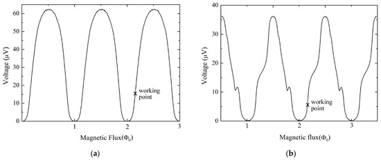
Figure 2.
Voltage vs. magnetic flux characteristics of the SQUID current sensors in parallel (a) and series configuration (b), measured at T = 4.2 K. The bias currents are 26 and 28 μA for the parallel and series configuration, respectively. The crosses indicate the working point for the noise measurements corresponding for both configurations to about 0.15 Φ0 with respect a minimum (nΦ0).
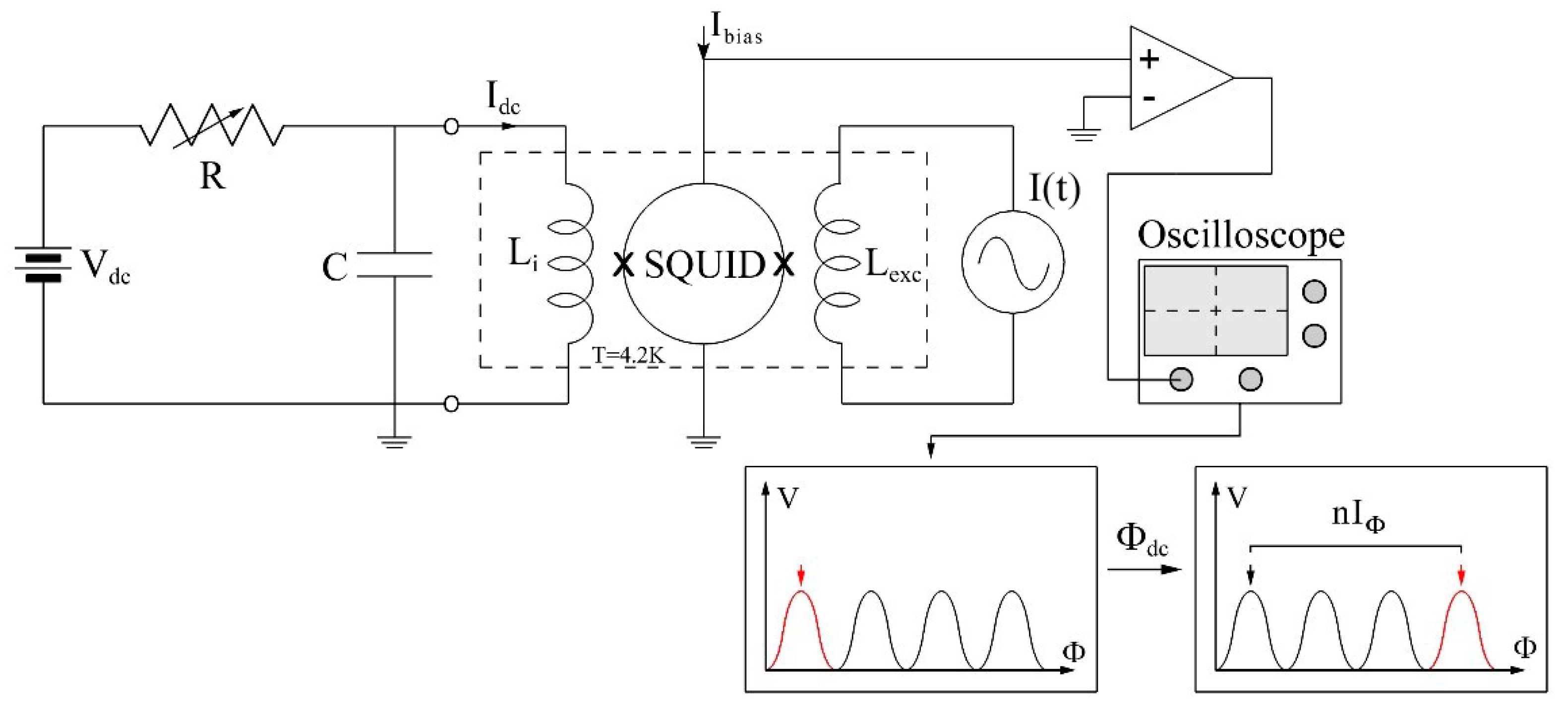
As mentioned above, a key factor of a current sensor is the current responsivity. It can be easily obtained by measuring the dc current to feed in the signal coil to couple one flux quantum (Φ0) into the SQUID. The measurement scheme is reported in Figure 3. An ac current source is connected to an excitation coil Lexc to display the V-Φ characteristics and a dc current is generated by a battery via a variable resistor and is fed in the input coil of the SQUID. In such a way, a magnetic flux offset is obtained as observed on an x-axis shift of the magnetic flux-to-voltage characteristic. The current sensitivity is obtained by measuring the current needed to produce one flux quantum shift. For a more accurate evaluation, a large number of Φ0 shifts is induced.
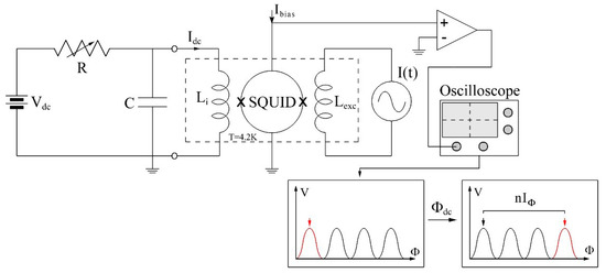
Figure 3.
Measurement scheme for evaluation of the current−to−magnetic−flux transfer factor (IΦ) of both SQUID sensors.
A quite-high-value capacitor (10 µF) connected to the ground (Figure 3) acts as a filtering stage to reduce the effect of the radiofrequency disturbance on the SQUID voltage swing. The measured current sensitivities for the parallel and series configurations are IΦ,p = 0.25 µA/Φ0 and IΦ,s = 0.36 µA/Φ0, respectively. These values are quite close, as in the starting aim, and the small mismatch is due to the requirement to keep a limited inductance in the series case to avoid an excessive increase in βL value.
Figure 4 reports the magnetic flux noise spectral density, as usual, for both devices. The measurements were performed at T = 4.2 K in small signal mode, biasing the sensor with a dc magnetic flux at its maximum responsivity point and using a spectrum analyzer (Hewlett Packard 3566A). The magnetic flux biases corresponding to the maximum responsivity are ΦB ≅ 0.15 Φ0 (Figure 2) for both configurations. The sensors show a comparable level of magnetic flux noise, which in the white region results in √SΦ,P = 3.8 µΦ0/√Hz and √SΦ,S = 5.3 µΦ0/√Hz. Note that both sensors are not affected by an excess of flicker noise since the 1/f corner starts at quite a low frequency, as is evident from the linear spectra with higher resolution in that range.
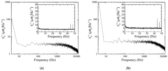
Figure 4.
Spectral densities of magnetic flux noise of the current sensors in the parallel (a) and series configuration (b). In the insets, the same measurements in the linear scale and in the low-frequency range are reported.
It is worth noting that the amplifier voltage noise does not significantly contribute to the overall noise. In fact, with the amplifier voltage noise being equal to SV,E1/2 = 0.7 nV/Hz1/2, the contribution to the magnetic flux noise is SΦ,E1/2 = SV,E 1/2/VΦ = 2.0 μΦ0/Hz1/2 for the parallel configuration and 2.4 μΦ0/Hz1/2 for the series one. Since the overall magnetic flux noises reported are SΦ,T1/2 = 3.8 μΦ0/Hz1/2 and 5.3 μΦ0/Hz1/2 for the parallel and series configuration, respectively, the intrinsic magnetic noise is SΦ,i1/2 = (SΦ,T − SΦ,E)1/2 = 3.2 μΦ0/Hz1/2 for the parallel configuration and 4.7 μΦ0/Hz1/2 for the series one.
The current noise spectral density is proportional to the SQUID magnetic flux noise by the current sensitivity, following a simple expression:
Despite the βL value in the series case being larger than the parallel one, the performance of these devices is quite similar, thanks to the local enhancement of responsivity due to presence of a resonance and the insertion of a damping resistance in the SQUID washer that softens the effect of the large βL value [17]. Note that such sensitivities represent the state of the art of gradiometric current sensors, having in addition a common rejection factor tied to photolithography accuracy, which is of the order 10−6. For higher performance, a more complicated design is required, such as those based on two-stage configurations [22,23,24,25,26].
4. Conclusions
In conclusion, the aim of this work was the realization of a current sensor that is as simple as possible and can cover most of the applications, while at the same time having a high rejection factor to work even in poorly shielded environments.
In particular, we designed, fabricated and characterized at liquid helium temperature (T = 4.2 K) SQUID current sensors in two different configurations: double-parallel washer and double-series washer. The performances in terms of both current sensitivity and spectral density of current noise are comparable, allowing in both cases for the measurement of ac current as low as 1–2 pA per bandwidth unit. The double-parallel washer exhibits smooth and resonance−free voltage–magnetic flux characteristics, ensuring greater stability during work operations, but at the same time, a circulating current in the external SQUID loop in the presence of an external constant magnetic field. On the other hand, the double-series washer exhibits input coil resonance, but a better common rejection factor in the presence of a constant magnetic field, as the screening current is completely canceled. However, considering the experimental performance of both configurations, there is no doubt that the SQUID sensor in parallel configuration is better in terms of performance, stability and reliability.
It is worth stressing that these quantum current sensors can be also successfully employed in axial gradiometers where the external superconducting antennas are connected to a high-inductance input coil of a SQUID in a double-washer configuration [27].
The results reported here are certainly of interest for superconducting devices, and more generally, for quantum sensing.
Author Contributions
Conceptualization, A.V. and C.G.; Formal analysis, A.V. and C.G.; Investigation, A.V. and C.G.; Methodology, A.V. and C.G.; Supervision, C.G.; Writing—original draft, A.V. All authors have read and agreed to the published version of the manuscript.
Funding
This research received no external funding.
Institutional Review Board Statement
Not applicable.
Informed Consent Statement
Not applicable.
Data Availability Statement
Not applicable.
Conflicts of Interest
The authors declare no conflict of interest.
References
- Seidel, P. (Ed.) Applied Superconductivity: Handbook on Devices and Applications, 1st ed.; Wiley-VCH Verlag GmbH & Co. KgaA: Weinheim, Germany, 2015. [Google Scholar]
- Kominis, I.; Kornack, T.; Allred, J.; Romalis, M. A subfemtotesla multichannel atomic magnetometer. Nature 2003, 422, 596. [Google Scholar] [CrossRef] [PubMed]
- Pannetier, M.; Fermon, C.; Le Goff, G.; Simola, J.; Kerr, E. Femtotesla magnetic field measurement with magnetoresistive sensors. Science 2004, 304, 1648. [Google Scholar] [CrossRef] [PubMed]
- Taylor, J.; Cappellaro, P.; Childress, L.; Jiang, L.; Budker, D.; Hemmer, P.; Yacoby, A.; Walsworth, R.; Lukin, M. High-sensitivity diamond magnetometer with nanoscale resolution. Nat. Phys. 2008, 4, 810. [Google Scholar] [CrossRef]
- Granata, C.; Vettoliere, A. Nano Superconducting Quantum Interference device: A powerful tool for nanoscale investigations. Phys. Rep. 2016, 614, 1. [Google Scholar] [CrossRef]
- Fagaly, R. Superconducting quantum interference device instruments and applications. Rev. Sci. Instrum. 2006, 77, 101101. [Google Scholar] [CrossRef]
- Clarke, J.; Braginski, A.I. (Eds.) The SQUID Handbook Vol I: Fundamentals and Technology of SQUIDs and SQUID Systems, 1st ed.; Wiley-VCH Verlag GmbH & Co. KgaA: Weinheim, Germany, 2004. [Google Scholar]
- Barone, A.; Paterno, G. Physics and Applications of the Josephson Effect; John Wiley & Sons: New York, NY, USA, 1982. [Google Scholar]
- Askerzade, I.; Bozbey, A.; Canturk, M. Modern Aspects of Josephson Dynamics and Superconductivity Electronics; Springer: Berlin/Heidelberg, Germany, 2017. [Google Scholar]
- Clarke, J.; Braginski, A.I. (Eds.) The SQUID Handbook Vol II: Application of SQUIDs and SQUID Systems; Wiley-VCH Verlag GmbH & Co. KgaA: Weinheim, Germany, 2006. [Google Scholar]
- Granata, C.; Vettoliere, A.; Nappi, C.; Lisitskiy, M.P.; Russo, M. Long baseline planar superconducting gradiometer for biomagnetic imaging. Appl. Phys. Lett. 2009, 95, 042502. [Google Scholar] [CrossRef]
- Cantor, R. Dc-SQUIDs: Design, optimization and practical applications. In SQUID Sensors: Fundamentals, Fabrication and Applications; NATO ASI, Series E: Applied Science; Weinstock, H., Ed.; Kluwer Academic Publisher: Dordrecht, The Netherlands, 1996; Volume 329, p. 179. [Google Scholar]
- Ketchen, M.B.; Jaycox, J.M. Ultra-low-noise tunnel junction dc SQUID with a tightly coupled planar input coil. Appl. Phys. Lett. 1982, 40, 736. [Google Scholar] [CrossRef]
- Tesche, C.; Clarke, J. dc SQUID: Noise and optimization. J. Low Temp. Phys. 1977, 29, 301. [Google Scholar] [CrossRef]
- Ketchen, M.B.; Stawiasz, K.G.; Pearson, D.J.; Brunner, T.A.; Hu, C.K.; Jaso, M.A.; Manny, M.P.; Parsons, A.A.; Stein, K.J. Sub-pm linewidth input coils for low TC integrated thin-film dc superconducting quantum interference devices. Appl. Phys. Lett. 1992, 61, 336. [Google Scholar] [CrossRef]
- McCumber, D.E. Effect of ac impedance on dc voltage-current characteristics of Josephson junctions. J. Appl. Phys. 1968, 39, 3113. [Google Scholar] [CrossRef]
- Enpuku, K.; Yoshida, K. Resistively shunted dc SQUID coupled to an input coil. J. Appl. Phys. 1986, 59, 1714. [Google Scholar] [CrossRef]
- Vettoliere, A.; Talamo, O.; Ruggiero, B.; Silvestrini, P.; Granata, C. Effect of critical current spread on the noise performance of SQUID magnetometers: An experimental study. Phys. C 2018, 555, 38. [Google Scholar] [CrossRef]
- Enpuku, K.; Minotani, T. Distortion of voltage vs. flux relation of dc SQUID coupled to multiturn input coil due to input coil resonance combined with capacitive-feedback effect. Appl. Supercond. 1998, 5, 419. [Google Scholar] [CrossRef]
- Minotani, T.; Enpuku, K.; Kuroki, Y. Effect of capacitive feedback on the characteristics of direct current superconducting quantum interference device coupled to a multiturn input coil. J. Appl. Phys. 1997, 82, 457. [Google Scholar] [CrossRef]
- Vettoliere, A.; Granata, C. Superconductive quantum interference magnetometer with high sensitivity achieved by an induced resonance. Rev. Sci. Instrum. 2014, 85, 085006. [Google Scholar] [CrossRef] [PubMed]
- Drung, D.; Aßmann, C.; Beyer, J.; Kirste, A.; Peters, M.; Ruede, F.; Schurig, T. Highly Sensitive and Easy-to-Use SQUID Sensors. IEEE Trans. Appl. Supercond. 2007, 17, 699. [Google Scholar] [CrossRef]
- Schmelz, M.; Zakosarenko, V.; Schonau, T.; Anders, S.; Kunert, J.; Meyer, M.; Meyer, H.G.; Stolz, R. A new family of field-stable and highly sensitive SQUID current sensors based on sub-micrometer cross-type Josephson junctions. Supercond. Sci. Technol. 2017, 25, 074010. [Google Scholar] [CrossRef]
- Granata, C.; Vettoliere, A.; Russo, M. An ultralow noise current amplifier based on superconducting quantum interference device for high sensitivity applications. Rev. Sci. Instrum. 2011, 82, 013901. [Google Scholar] [CrossRef] [PubMed]
- Polushkin, V.; Gu, E.; Glowacka, D.; Goldie, D.; Lumley, J. A tightly coupled dc SQUID with an intermediary transformer. Phys. C 2002, 367, 280. [Google Scholar] [CrossRef]
- Zakosarenko, V.; Schmelz, M.; Stolz, R.; Schonau, T.; Fritzsch, L.; Anders, S.; Meyer, H.G. Femtoammeter on the base of SQUID with thin-film flux transformer. Supercond. Sci. Technol. 2012, 25, 095014. [Google Scholar] [CrossRef]
- Vrba, J. SQUID gradiometer in real environment. In SQUID Sensors: Fundamentals, Fabrication and Applications; NATO ASI, Series E: Applied Science; Weinstock, H., Ed.; Kluwer Academic Publisher: Dordrecht, The Netherlands, 1996; Volume 329, p. 117. [Google Scholar]

Publisher’s Note: MDPI stays neutral with regard to jurisdictional claims in published maps and institutional affiliations. |
© 2022 by the authors. Licensee MDPI, Basel, Switzerland. This article is an open access article distributed under the terms and conditions of the Creative Commons Attribution (CC BY) license (https://creativecommons.org/licenses/by/4.0/).