Article

Fine Characterization Method of Concrete Internal Cracks Based on Borehole Optical Imaging

1
State Key Laboratory of Geomechanics and Geotechnical Engineering, Institute of Rock and Soil Mechanics, Chinese Academy of Sciences, Wuhan 430071, China
2
University of Chinese Academy of Sciences, Beijing 100049, China
*
Author to whom correspondence should be addressed.
Appl. Sci. 2022, 12(18), 9080; https://doi.org/10.3390/app12189080
Submission received: 28 August 2022 / Revised: 6 September 2022 / Accepted: 6 September 2022 / Published: 9 September 2022

Abstract

:
The internal cracks of concrete are very important in the safety evaluation of structures, but there is a lack of fine characterization methods at present. Borehole cameras are a piece of in situ borehole detection technology which can measure the structural elements of a borehole wall with high precision. In this paper, borehole camera technology is used to measure the concrete cracks of a tunnel floor, and the morphological characteristics (depth, width, and orientation) of the cracks are analyzed. The results show that the average extension depth of the crack extending from the orifice exceeds 1.195 m, and the width decreases with the increase in depth. The crack orientation is basically stable, with the maximum deviation of 19° at the orifice of different boreholes and 30° at different depths of the same borehole. The crack inside the concrete (not extending to the orifice) usually has a small extension depth and a relatively stable width, but the crack orientation changes greatly. The coarse aggregate and concrete interface have different effects on the extension direction of cracks. This paper also conducted a second measurement on two of the boreholes after an interval of 15 days, and found the difference in crack development in the two measurements. The work of this paper provides a new attempt for the detection and monitoring of concrete crack morphology.

1. Introduction

Concrete is one of the most common building materials which is widely used in infrastructure construction such as roads, bridges, tunnels, dams, and housing construction [1,2,3,4]. Concrete is a brittle material with low tensile strength. In the long-term operation process, cracks will inevitably occur due to uneven load, high-temperature thermal deformation, and erosion [5,6,7]. Cracks in concrete structures will become channels for external aggressive agents, thus accelerating the damage of buildings [8,9]. When the depth and width of cracks exceed the critical value borne by the concrete structure, it will seriously affect the mechanical properties of the concrete structure [10], and may even lead to major safety accidents and unnecessary losses.
The detection of concrete cracks is extremely important. The traditional way of visual and manual measurement can only be limited to the geometric shape measurement of concrete surface cracks, but cannot be applied to the description of the expansion shape of internal cracks. With the continuous breakthrough of computer technology and sensor technology, researchers have developed ground-penetrating radar [11,12,13], ultrasonic technology [14,15,16], and a variety of pavement sensors to detect the morphological characteristics of internal cracks in concrete. The ground-penetrating radar can only detect cracks with high accuracy within a limited depth range. When measuring deep cracks, the measurement accuracy will be seriously damaged, and the actual operation requires a high level of experience of inspectors [17,18]. Ultrasonic testing technology uses couplants to couple transducers to the surface of the concrete pavement, which leads to inconvenient operation in practice and requires longer testing time [19]. Due to the nonuniformity of concrete, this test method usually leads to high scattering and attenuation of transmitted pulses, and the final spatial resolution may be unsatisfactory [20,21]. In addition, common detection methods include optical-fiber sensor detection technology, infrared-imaging detection technology, etc. [22,23,24,25], but the complexity of field work and the inaccuracy and cost of test results make it difficult to meet the requirements of the fine description of concrete cracks.
Digital image detection is an intuitive and economical crack characterization method [26,27,28]. Thanks to the continuous breakthroughs of optical photography technology [29,30,31] and digital-image-processing technology [32,33,34], the detection method based on digital image technology has attracted the attention of researchers. At present, the optical images of concrete cracks are mainly captured by handheld industrial cameras, vehicle-mounted cameras, and unmanned aerial vehicles. Obviously, these methods can only obtain the surface cracks of concrete buildings, so they can only characterize the geometric shape of concrete surface cracks. However, it is impossible to describe the hidden cracks and the extension and morphological characteristics of cracks in the concrete. In recent years, the research on image detection has focused on algorithm implementation to identify the width and orientation of cracks in the concrete surface image [35,36,37,38]. However, there is a lack of research on the measurement and characterization of the internal crack morphology of concrete. Digital borehole camera technology [39,40] is an in situ detection method that can go deep into the interior of the borehole and obtain 360° high-resolution optical images of the borehole wall. The equipment has excellent waterproof performance, so that it can work normally in a deep borehole with high-pressure water, but it needs to replace sewage with clean water [41]. This technology has already been successfully applied in the field of geotechnical engineering investigation, and has achieved very effective detection results [42,43,44]. In this study, digital borehole camera detection was carried out by using core drilling which is necessary in the detection of concrete cracks [45]. The high-resolution optical image of the borehole wall was obtained, and the depth, width, and orientation of the crack in the image are quantitatively analyzed. This is a new attempt of crack detection, which provides a new method for describing the morphological characteristics of internal cracks in concrete, and the measurement results are satisfactory.

2. Crack Image Acquisition

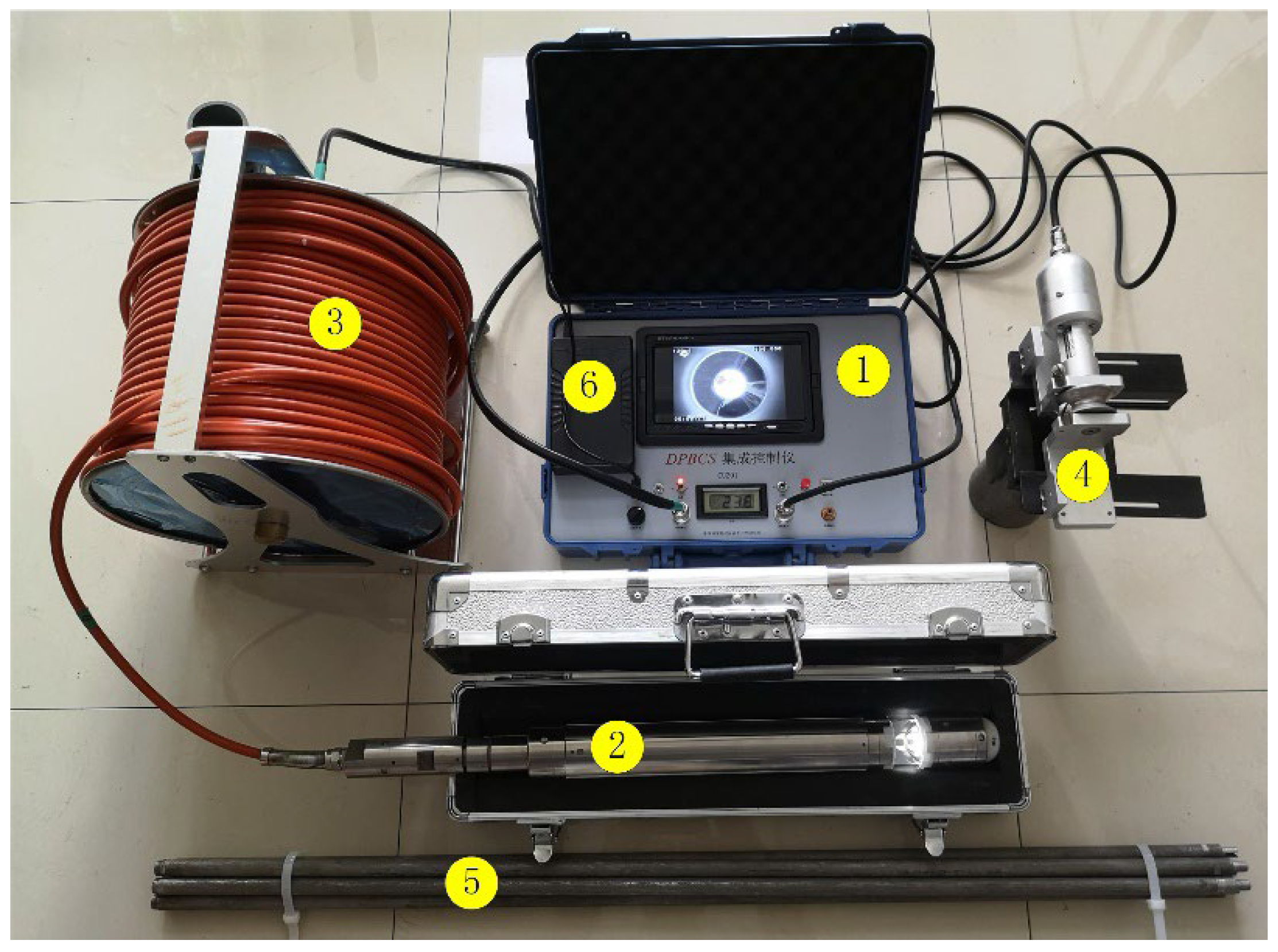
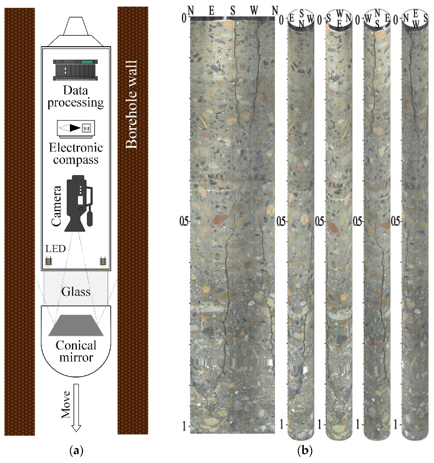
2.1. Borehole Camera Technology

A borehole camera system is a kind of in situ optical measurement technology. This technology records the structural information of the borehole wall by continuous photography or video recording, and the measurement results are intuitive and low-cost. The equipment used in this paper is the digital panoramic borehole camera system (DPBCS) developed by the Institute of Rock and Soil Mechanics, Chinese Academy of Sciences. The system mainly includes a control box, optical probe, flexible cable, depth recorder, rigid push rod (used in nonvertical downward boreholes), and power supply components. The structural diagram of the DPBCS is shown in Figure 1.
The optical probe is the most critical component of the system, mainly including a data-processing module, electronic compass, LED light source, glass window, camera, and conical mirror, as shown in Figure 2a. The optical probe has three sizes, with diameters of 31 mm, 51 mm, and 73 mm, respectively, and corresponding lengths of 471 mm, 462 mm, and 587 mm, respectively. The functions of the three types of probes are the same, and the probe closest to the borehole diameter is usually selected for use. The use of conical mirror technology is creative, so that the 360° borehole wall reflects into a planar panoramic image. The advantage of this technology is that the camera can capture a video image of the 360° borehole wall at the same time without rotating the probe. The LED light source illuminates the borehole wall through the glass window, and the light is reflected into the camera by the conical mirror. The conical mirror is located in the focal length range of the fixed focus lens. The electronic compass is fixed coaxially with the camera, with an accuracy of 0.1°. Even if the probe shakes or rotates in the borehole, the electronic compass can determine its orientation.
The depth encoder is fixed at the orifice to record the depth of the optical probe in the borehole with an accuracy of 0.1 mm. The flexible cable descends the optical probe to the bottom of the borehole at a constant speed through the depth encoder, and the lowering speed shall not exceed 1.5 m/s. In addition, the flexible cable is also a channel for power supply and data transmission between the control box and the optical probe. The control box superimposes the video data, orientation data and depth data in real time to ensure that the depth and orientation of each frame of the image are determined.
Figure 2a shows the measurement process. As the optical probe moves in the borehole, the video image, orientation information, and depth information of the borehole wall structure are collected and saved. Because the conical mirror technology reflects the panoramic strip image, the image must be restored to a form convenient for viewing through a certain algorithm. As shown in Figure 2b, the borehole wall image collected by the borehole camera system is shown. The first picture is the plan expansion of the borehole wall along the due north direction, and the other four are borehole histograms from different perspectives. In the image, the aggregate and cracks on the borehole wall can be clearly seen. The top of the image is the orientation data, and the left is the depth data; that is, the coordinates of each pixel on the borehole wall are determined.

2.2. Measurement Accuracy Analysis

The measurement accuracy of the concrete crack is also the resolution of the borehole wall image. The hole wall image is a dot matrix composed of pixels, so it is necessary to analyze the corresponding relationship between the image pixels and the real size of the observed points. The axial resolution of the borehole wall image obtained by the digital borehole camera system can reach 0.1 mm/pix. The circumferential resolution of the image is related to the borehole diameter. The borehole wall images obtained from exploration boreholes with different diameters correspond to different circumferential resolutions. The maximum number of pixels in the circumferential direction of the borehole wall image obtained by the digital borehole camera system is 2560, and the circumferential resolution of the image in the conventional exploration boreholes with different diameters is shown in Figure 3.
It can be seen from Figure 3 that the circumferential resolution of the hole wall image decreases with the increase in the hole diameter. The resolution is 0.037 mm/pix in 30 mm diameter holes and 0.16 mm/pix in 130 mm diameter holes. The measurement accuracy is fully sufficient in concrete crack detection.

2.3. Measuring Project

The measurement project is a highway tunnel with open excavation and concealed burial construction. After backfilling with soil and stone, a long and deep crack appeared on the bottom plate along the axis of the tunnel, as shown in Figure 4. In order to quantitatively evaluate the cracks, several drilling and coring operations were carried out at the crack location. However, the drilled concrete core cannot accurately describe the characteristics of cracks. Because some concrete cores are broken and damaged, it is impossible to determine whether the damage is caused by drilling factors or crack expansion. More importantly, it is difficult to determine the width of cracks and the extension direction inside the concrete, and it is impossible to evaluate the development of cracks with time through the concrete core.
Therefore, in order to quantitatively characterize the morphological characteristics of internal cracks in concrete, the cracks on the borehole wall were quantitatively measured using borehole camera technology in the borehole after coring. Due to the large number of on-site boreholes, we selected nine representative boreholes for measurement. The borehole number and measurement depth are shown in Table 1. The diameter of all boreholes was 57 mm, and the diameter of the optical probe used in this paper was 51 mm. Figure 5 shows the measurement site and measurement equipment.
After measurement, high-resolution borehole wall images of nine measurement holes were obtained, as shown in Figure 6. In the borehole wall image, structural information, such as aggregate, damage, and cracks, can be clearly observed. For the convenience of viewing, the shape of the crack is depicted with red lines in Figure 6. It should be reminded that the wide black vertical defects in the figure are not cracks, but borehole wall defects caused by the overlapping of adjacent boreholes. There are two types of cracks in the nine boreholes, the cracks that expand from the orifice (zk15 + 025, zk14 + 896, zk15 + 018, zk14 + 994, zk14 + 858, and zk14 + 870) and the cracks inside the concrete (not extending to the orifice; zk15 + 025, zk14 + 931, zk14 + 819, and zk14 + 903.5).

3. Morphological Characteristics Analysis of Cracks

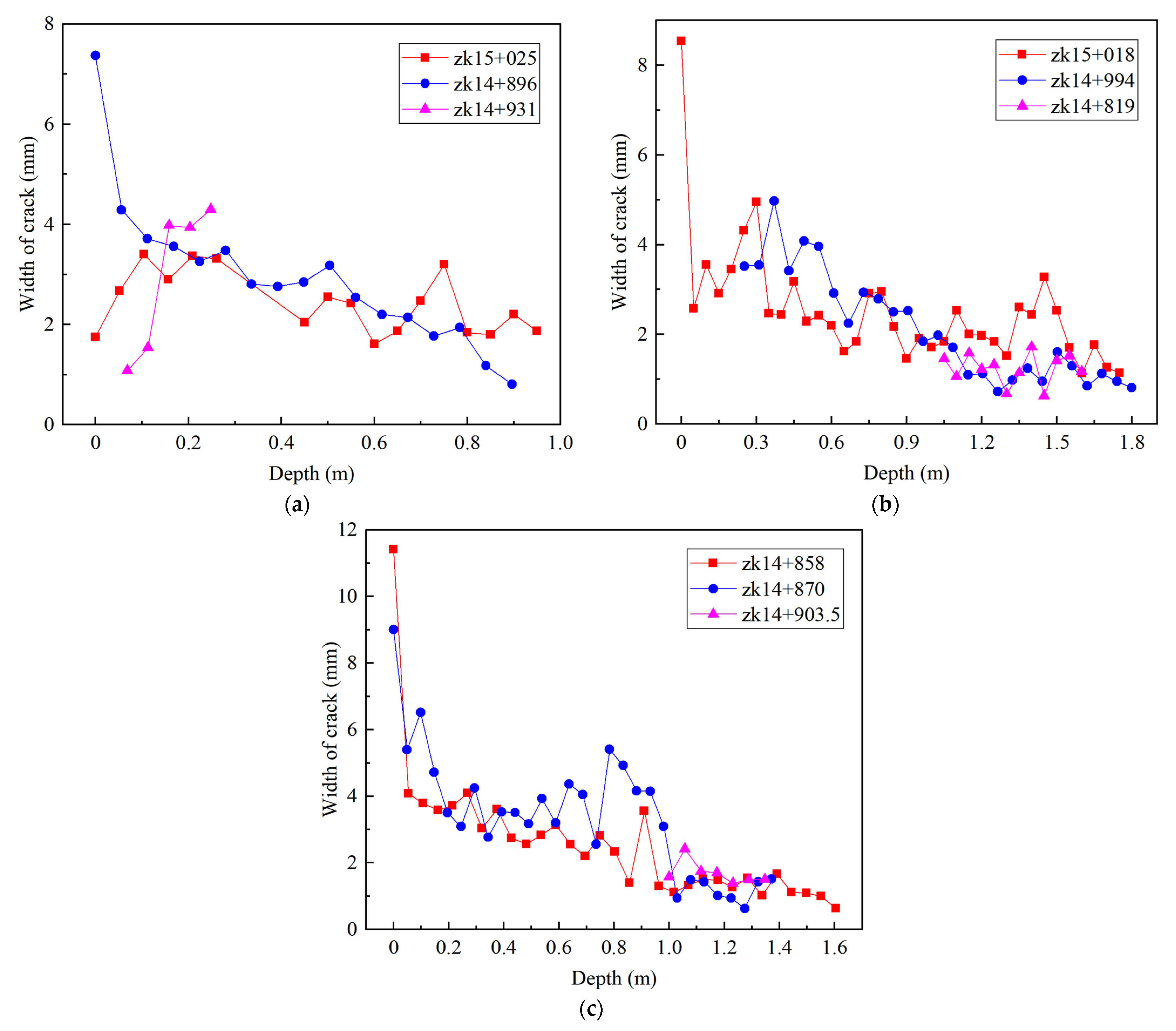
3.1. Analysis of Width and Depth

Depth and width are important parameters to describe the morphological characteristics of cracks, and are also the main parameters for the safety evaluation of concrete buildings. In this paper, the crack depth and width in nine boreholes were measured and statistically analyzed, as shown in Figure 7.
(1) In borehole zk15 + 025, there were two discontinuous cracks; the first crack started from the orifice and extended to 0.28 m. The second crack started from 0.42 m and extended to 0.97 m. The crack width of the first crack was relatively large, and the extension of the two cracks was relatively small. There was no obvious characteristic of the change in crack width. (2) In zk14 + 896, the crack started from the orifice and extended to 0.81 m. The crack width reached 7.37 mm at the orifice, and the crack width gradually decreased with the increase in depth. (3) In borehole zk14 + 931, the crack started from 0.07 m and extended to 0.33 m. The crack seemed to form a closed oval, which may have been caused by the intersection of adjacent boreholes. The crack extension depth was small, and the crack width increased with the depth. (4) In borehole zk15 + 018, the crack started from the orifice and extended to 1.78 m. The crack width was large at the orifice, reaching 8.54 mm, and then rapidly decreased. The fluctuation of the crack width at local positions was obvious, but decreased with the increase in depth in macro. (5) In borehole zk14 + 994, due to the influence of the intersection of adjacent boreholes, the morphology of cracks at the orifice was not observed. In the borehole wall image, the crack started from 0.23 m and extended to 1.65 m. The crack width was relatively small at the initial position, and also showed a law of decreasing with the increase in depth. (6) In borehole zk14 + 819, there was no obvious crack before 1 m depth. In the borehole wall image, the crack started from 1.09 m and extended to the concrete interface (1.64 m). The crack extension depth was not large, and the change law of crack width was not obvious. (7) In borehole zk14 + 858, the crack started from the orifice, penetrated the concrete interface, and extended to 1.38 m. The crack was wide at the orifice, reaching 11.42 mm, and then rapidly decreased. The crack width also decreased with the increase in depth. (8) In borehole zk14 + 870, the crack started from the orifice, penetrated the concrete interface, and extended to 1.36 m. The crack was also relatively large at the orifice, reaching 9.01 mm. The crack width fluctuated greatly at local positions, but it still showed a trend of decreasing with the increase in depth. (9) In borehole zk14 + 903.5, the upper half of the borehole wall was complete, and the crack started from 0.96 m and extended to 1.36 m. The crack width was basically stable and changed little.
Except for borehole zk15 + 025, the extension depth of cracks extending from the orifice was relatively large. There were five boreholes with a crack depth of more than 1 m and three boreholes with a crack depth of more than 1.5 m, accounting for 55.6% and 33.3%, respectively. The extension depth of cracks inside the concrete was relatively small. The width of the crack at the orifice was large, but it often decreased rapidly after a short distance from the orifice. The larger crack width at the orifice may have been caused by the falling block caused by the interference of external factors such as vehicles and pedestrians. The cracks extending from the orifice showed a trend where the width gradually decreased with the increase in depth. However, the fluctuation of the width of cracks inside the concrete was relatively small (except for borehole zk14 + 931), which was not significantly affected by the depth.

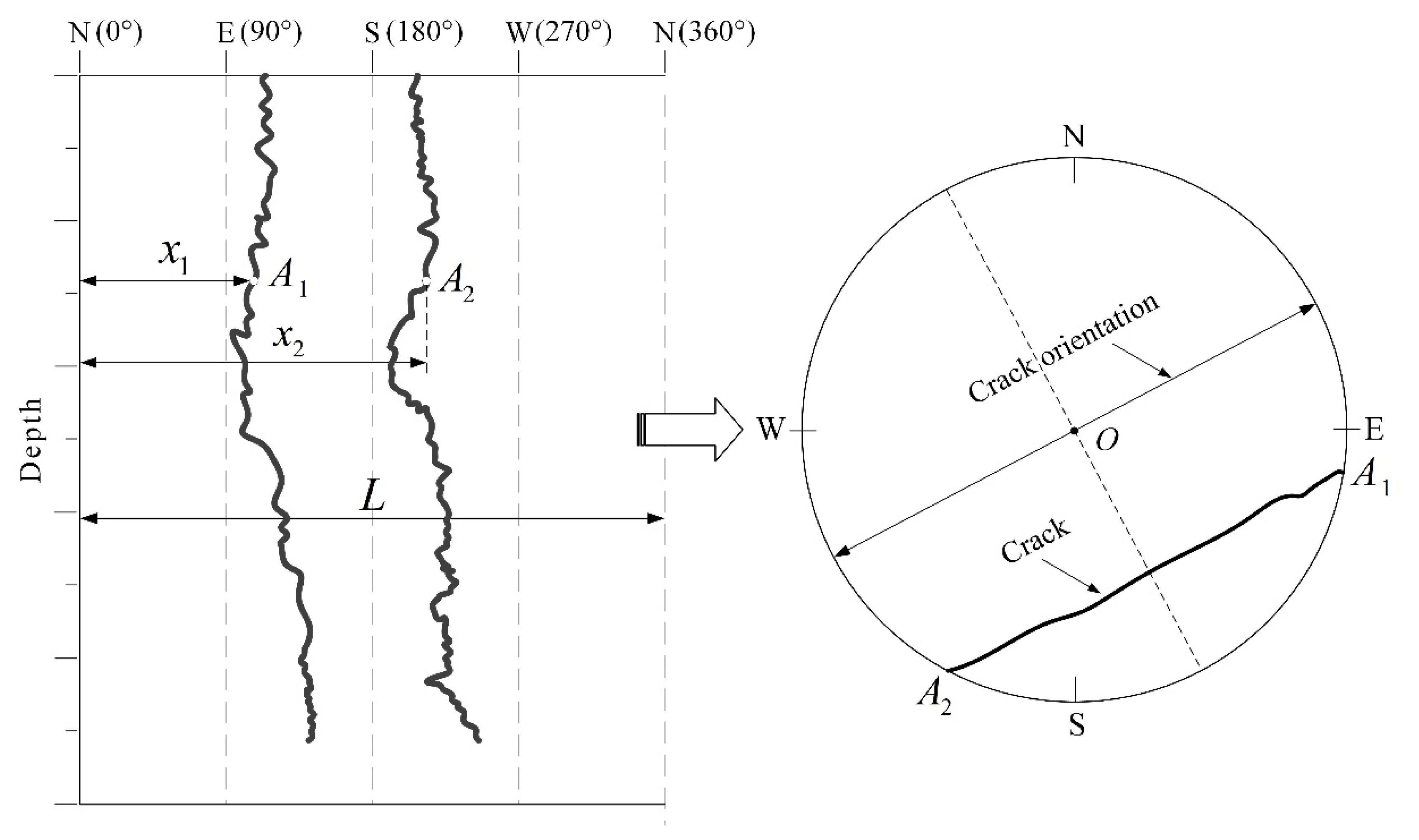
3.2. Analysis of Crack Orientation

The extension orientation of the crack is very important for describing the morphological characteristics. An accurate understanding of the crack orientation is very important for analyzing the cause of crack initiation and subsequent repair. When the crack intersects with the borehole, two cracks will appear on the expanded image of the borehole wall, as shown in Figure 8. The crack may intersect with the borehole at any angle, and when the crack does not pass through the borehole center, the orientation of the crack cannot be directly seen on the borehole wall image. Figure 8 shows the calculation principle of the crack orientation at any position on the borehole wall. Suppose that at a certain depth in the borehole wall image, the two points on the crack are A 1 and A 2 , respectively, then the orientation of the crack at this depth can be expressed as Equation (1):
γ = 1 2 L x 1 + x 2 × 360 ° ±   90 °
where γ is the orientation of the crack. x 1 and x 2 are the distances from A 1 and A 2 to the leftmost side (0°) of the borehole wall image, respectively. L is the perimeter of the borehole.
In this paper, the crack orientation at different depths in nine boreholes was calculated, and the statistical results are shown in Figure 9. It should be pointed out that the orientation can be calculated only when two cracks appear in the borehole wall image. (1) In borehole zk15 + 025, although the upper and lower cracks were not continuous, the orientation of the two cracks was very close, both distributed in the range of [142°,158°], and the crack orientation at the orifice was 151°. (2) In borehole zk14 + 896, the change in crack orientation was relatively gentle, distributed in the range of [114°,143°], and the fracture trend at the orifice was 143°. (3) In borehole zk14 + 931, the crack orientation was distributed in the range of [133°,144°]. (4) In borehole zk15 + 018, affected by the intersection of adjacent boreholes, only one crack appeared in the borehole wall image of the first 0.5 m, so the orientation of the crack cannot be calculated before 0.5 m. After 0.5 m, the crack orientation continued to change, gradually deflecting from the initial position of 145° to the due east direction until 80°. (5) In borehole zk14 + 994, there was only one crack in the borehole wall image of 0.5–0.8 m due to the intersection of adjacent boreholes, so the crack orientation could not be calculated in this section. The crack orientation of this borehole was distributed in the range of [94°,129°], and the crack orientation at the initial position was 112°. Before 0.9 m, the change in crack orientation was very small, and the crack orientation suddenly changed significantly within the range of 0.9–1 m, increasing from 94° to 129°. (6) In borehole zk14 + 819, the crack orientation continued to decrease from the initial position of 184° to 125°. (7) In borehole zk14 + 858, the orientation of the crack changed little before 0.9 m, and the orientation of the crack at the orifice was 132°. After passing through the concrete interface, the crack orientation changed significantly, continuously decreasing from 114° to 19°. (8) In borehole zk14 + 870, the crack orientation changed little, distributed in the range of [103°,132°], and the crack orientation at the orifice was 132°. (9) In borehole zk14 + 903.5, the crack orientation was distributed within the range of [122°,165°], and the crack orientation at the initial position was 165°.
There was little difference in the orientation of cracks at the orifice. The orientation of cracks at the orifice was measured in boreholes zk15 + 025, zk14 + 896, zk14 + 858, and z14 + 903.5, which were 151°, 143°, 132°, and 132°, respectively, and the maximum difference was only 19°. The orientation change of cracks at different depths in the same borehole was relatively small, and, basically, the deviation did not exceed 30°. However, after passing through the concrete interface and entering another different type of concrete, the orientation of cracks changed significantly. The change in crack orientation inside the concrete was relatively large. For example, in boreholes zk14 + 819 and zk14 + 903.5, the change in crack direction reached 59° and 43°, respectively, in a short extension depth. The crack extension in the concrete is affected by the coarse aggregate structure. The crack extends along the interface between coarse aggregate and mortar, and rarely directly penetrates the coarse aggregate, which affects the orientation of the crack to a certain extent, as shown in Figure 10. However, in this paper, the influence of coarse aggregate on the orientation of cracks that extended from the orifice was limited. After bypassing the coarse aggregate, the crack soon continues to extend along the previous orientation.
Although the electronic compass inside the optical probe has a measurement error of 0.1°, the error can be ignored relative to the influence of coarse aggregate on the orientation. In addition, the orientation of the borehole also causes measurement errors, so the verticality of the borehole should be guaranteed as much as possible. If the borehole is not vertical, the orientation of the borehole axis and the included angle with the horizontal direction are necessary to correct the error.

4. Discussion

The development of a crack is a dynamic process, and the change in its morphological characteristics with time is an important factor to be considered. The stable or slow development of crack morphology is the desired result of engineers. If the cracks continue to extend and widen over time, this will bring great difficulties to the evaluation and repair of concrete structures. Therefore, it is necessary to regularly observe the crack morphology. Due to the construction requirements, most of the boreholes were quickly blocked after the first measurement. Only boreholes zk15 + 018 and zk14 + 994 were allowed to remain as observation boreholes. Fifteen days after the first measurement, boreholes zk15 + 018 and zk14 + 994 were measured again with the same borehole camera equipment. Figure 11 shows the comparison of borehole wall images obtained from the two measurements. There was only a slight difference between the two measurement results. In borehole zk15 + 018, the second measurement found that the crack continued to extend 6 mm downward, while in borehole zk14 + 994, no significant crack extension was found. The crack width of the two boreholes at the orifice basically increased by 2 mm. This may be due to the vibration caused by vehicles and pedestrians on the tunnel surface, resulting in the falling off of mortar and aggregate. However, below the orifice, the crack width had no obvious expansion trend.
The development of cracks can be monitored by using the borehole camera technology to conduct periodic measurements in the same borehole. In this paper, subtle differences in the development of cracks were found in the two measurements, and the cracks observed in the two boreholes were basically in a stable state. However, since the number of boreholes measured in the second time was too small, it is arbitrary to give the development law of cracks in a large area. If the construction conditions permit, the number of observation boreholes and the measurement period shall be increased in similar monitoring schemes.
The borehole camera technology can accurately measure the morphological characteristics of the cracks on the borehole surface, but it cannot measure the cracks in the concrete around the borehole. By increasing the borehole density, a comprehensive analysis of multi-borehole data can help reduce the impact of this limitation. In addition, it is difficult for a single detection technology to fully meet the requirements, and the combined use of multiple measurement methods can make the results more detailed and comprehensive.

5. Conclusions

This paper introduces the borehole camera technology, which is an advanced technique for measuring in a borehole. It represents a new attempt to apply this technique to the measurement of the morphological characteristics of concrete cracks. The acquisition of a high-resolution borehole wall image provides a feasible scheme to accurately characterize the width, depth, orientation, and other valuable indicators of concrete internal cracks. Although this paper focused on the morphological characteristics of cracks in concrete, borehole camera technology can also be used to study the morphology and distribution characteristics of coarse aggregate. In addition, this technology can also be used for the fine measurement and characterization of internal structures or damages in other fields. For example, borehole cameras have been widely used for the measurement and statistical analysis of underground structures in geology and geotechnical engineering.
In the application case of this paper, nine boreholes were measured and the crack morphology characteristics were quantitatively characterized. The measurement results show that the average depth of the crack extending from the orifice was 1.195 m, and the width decreased with depth. The orientation of the crack in different boreholes was basically the same at the orifice, with a maximum deviation of 19°, and the orientation of the crack was basically stable from the orifice to the termination depth, with the deviation not exceeding 30°. However, the crack orientation will change obviously after passing through the concrete interface. The average extension depth of cracks inside the concrete was 0.443 m, and the change in width was relatively small, but the orientation changed greatly. Coarse aggregate in concrete will force cracks to change orientation at the local position. The induction effect of coarse aggregate characteristics (uniformity and morphological characteristics) on concrete orientation is a very meaningful topic. Obviously, borehole camera technology is an effective means for this research, and more attention will be paid to subsequent research.
Borehole camera technology is also an effective method for the long-term monitoring of fracture development. Although limited by construction requirements in this paper, the long-term measurement of multiple boreholes was not carried out. However, the difference in crack propagation was still found in two measurements, which is very meaningful and helpful for the evaluation and maintenance of concrete buildings.

Author Contributions

Conceptualization, C.W. (Chao Wang); methodology, Z.H. and Y.W.; software, C.W. (Chao Wang); validation, Z.H. and Y.W.; formal analysis, C.W. (Chuanying Wang); investigation, C.W. (Chao Wang), S.C. and Z.H.; resources, Z.H. and J.W.; data curation, Y.W. and S.C.; writing—original draft preparation, C.W. (Chao Wang) and Y.W.; writing—review and editing, C.W. (Chao Wang), C.W. (Chuanying Wang) and Z.H.; visualization, J.W.; supervision, C.W. (Chuanying Wang); project administration, S.H.; funding acquisition, Z.H. and J.W. All authors have read and agreed to the published version of the manuscript.

Funding

This research was funded by the Key Research and Development Program of Hubei Province, grant number 2021BAA201, the Systematic Project of Guangxi Key Laboratory of Disaster Prevention and Engineering Safety, grant number 2020ZDK015 and the National Natural Science Foundation of China, Grant numbers: 41731284, 41902294.

Institutional Review Board Statement

Not applicable.

Informed Consent Statement

Not applicable.

Data Availability Statement

The data presented in this study are available on request from the corresponding author.

Conflicts of Interest

The authors declare no conflict of interest.

References

  1. Damasceno, I.I.R.; Ferreira, M.D.P.; De Oliveira, D.R.C. RC beams with steel fibers under impact loads. Acta Sci. Technol. 2013, 36, 23. [Google Scholar] [CrossRef]
  2. Tarefder, R.A.; Ahmad, M. Evaluating the Relationship between Permeability and Moisture Damage of Asphalt Concrete Pavements. J. Mater. Civ. Eng. 2015, 27, 04014172. [Google Scholar] [CrossRef]
  3. Soumya; Pandey, A.D.; Das, R.; Mahesh, M.J.; Anvesh, S.; Saini, P. Structural analysis of a historical dam. Procedia Eng. 2016, 144, 140–147. [Google Scholar] [CrossRef]
  4. Cui, X.; Wang, Q.; Dai, J.; Zhang, R.; Li, S. Intelligent recognition of erosion damage to concrete based on improved YOLO-v3. Mater. Lett. 2021, 302, 130363. [Google Scholar] [CrossRef]
  5. Galouei, M.; Fakhimi, A. Size effect, material ductility and shape of fracture process zone in quasi-brittle materials. Comput. Geotech. 2015, 65, 126–135. [Google Scholar] [CrossRef]
  6. Wang, H.L.; Dai, J.G.; Sun, X.Y.; Xiao, Y.; Zhang, X.L. Characteristics of concrete cracks and their influence on chloride penetration. Constr. Build. Mater. 2016, 107, 216–225. [Google Scholar] [CrossRef]
  7. Jiang, W.; Zhou, G.; Wang, C.; Xue, Y.; Niu, C. Synthesis and self-healing properties of composite microcapsule based on sodium alginate/melamine-phenol–formaldehyde resin. Constr. Build. Mater. 2020, 271, 121541. [Google Scholar] [CrossRef]
  8. Zhou, C.; Li, K.; Pang, X. Geometry of crack network and its impact on transport properties of concrete. Cem. Concr. Res. 2012, 42, 1261–1272. [Google Scholar] [CrossRef]
  9. Li, M.; Chen, H.; Liu, L.; Lin, J.; Ullah, K. Permeability of concrete considering the synergetic effect of crack’s shape- and size-polydispersities on the percolation. Constr. Build. Mater. 2021, 315, 125684. [Google Scholar] [CrossRef]
  10. Li, K.; Li, L. Crack-altered durability properties and performance of structural concretes. Cem. Concr. Res. 2019, 124, 105811. [Google Scholar] [CrossRef]
  11. Fernandes, F.M.; Pais, J.C. Laboratory observation of cracks in road pavements with GPR. Constr. Build. Mater. 2017, 154, 1130–1138. [Google Scholar] [CrossRef]
  12. Tong, Z.; Yuan, D.; Gao, J.; Wei, Y.; Dou, H. Pavement-distress detection using ground-penetrating radar and network in networks. Constr. Build. Mater. 2019, 233, 117352. [Google Scholar] [CrossRef]
  13. Hong, S.; Chen, D.; Dong, B. Numerical simulation and mechanism analysis of GPR-based reinforcement corrosion detection. Constr. Build. Mater. 2021, 317, 125913. [Google Scholar] [CrossRef]
  14. Choi, P.; Kim, D.-H.; Lee, B.-H.; Won, M.C. Application of ultrasonic shear-wave tomography to identify horizontal crack or delamination in concrete pavement and bridge. Constr. Build. Mater. 2016, 121, 81–91. [Google Scholar] [CrossRef]
  15. Cook, K.; Garg, N.; Singh, A.; Flynn, M. Detection of Delamination in the HMA Layer of Runway Pavement Structure Using Asphalt Strain Gauges. J. Transp. Eng. 2016, 142, 04016047. [Google Scholar] [CrossRef]
  16. Grabke, S.; Clauß, F.; Bletzinger, K.-U.; Ahrens, M.A.; Mark, P.; Wüchner, R. Damage Detection at a Reinforced Concrete Specimen with Coda Wave Interferometry. Materials 2021, 14, 5013. [Google Scholar] [CrossRef]
  17. Xu, X.; Zeng, Q.; Li, D.; Wu, J.; Wu, X.; Shen, J. GPR detection of several common subsurface voids inside dikes and dams. Eng. Geol. 2010, 111, 31–42. [Google Scholar] [CrossRef]
  18. Song, X.; Xiang, D.; Zhou, K.; Su, Y. Fast Prescreening for GPR Antipersonnel Mine Detection via Go Decomposition. IEEE Geosci. Remote Sens. Lett. 2018, 16, 15–19. [Google Scholar] [CrossRef]
  19. Tsai, Y.-C.; Kaul, V.; Mersereau, R.M. Critical Assessment of Pavement Distress Segmentation Methods. J. Transp. Eng. 2010, 136, 11–19. [Google Scholar] [CrossRef]
  20. Asadollahi, A.; Khazanovich, L. Numerical investigation of the effect of heterogeneity on the attenuation of shear waves in concrete. Ultrasonics 2018, 91, 34–44. [Google Scholar] [CrossRef]
  21. Chekroun, M.; Le Marrec, L.; Abraham, O.; Durand, O.; Villain, G. Analysis of coherent surface wave dispersion and attenu-ation for non-destructive testing of concrete. Ultrasonics 2009, 49, 743–751. [Google Scholar] [CrossRef] [PubMed]
  22. Chapeleau, X.; Blanc, J.; Hornych, P.; Gautier, J.L.; Carroget, J. Assessment of cracks detection in pavement by a distributed fber optic sensing technology. J. Civil. Struct. Health Monit. 2017, 7, 459–470. [Google Scholar] [CrossRef]
  23. De Maeijer, P.K.; Luyckx, G.; Vuye, C.; Voet, E.; Bergh, W.V.D.; Vanlanduit, S.; Braspenninckx, J.; Stevens, N.; De Wolf, J. Fiber Optics Sensors in Asphalt Pavement: State-of-the-Art Review. Infrastructures 2019, 4, 36. [Google Scholar] [CrossRef]
  24. Zheng, D.; Tan, S.; Li, X.; Cai, H. Research on the Infrared Thermographic Detection of Concrete under Solar Heating. Adv. Civ. Eng. 2021, 2021, 6692729. [Google Scholar] [CrossRef]
  25. Sirca, G.F.; Adeli, H. Infrared Thermography for Detecting Defects in Concrete Structures. J. Civ. Eng. Manag. 2018, 24, 508–515. [Google Scholar] [CrossRef]
  26. Payab, M.; Abbasina, R.; Khanzadi, M. A Brief Review and a New Graph-Based Image Analysis for Concrete Crack Quanti-fication. Arch. Comput. Methods Eng. 2019, 26, 347–365. [Google Scholar] [CrossRef]
  27. Shan, B.; Zheng, S.; Ou, J. A stereovision-based crack width detection approach for concrete surface assessment. KSCE J. Civ. Eng. 2015, 20, 803–812. [Google Scholar] [CrossRef]
  28. Zhao, P.; Zsaki, A.M.; Nokken, M.R. Using digital image correlation to evaluate plastic shrinkage cracking in cement-based materials. Constr. Build. Mater. 2018, 182, 108–117. [Google Scholar] [CrossRef]
  29. Ahmed, M.; Haas, C.T.; Haas, R. Toward low-cost 3D automatic pavement distress surveying: The close range photogrammetry approach. Can. J. Civ. Eng. 2011, 38, 1301–1313. [Google Scholar]
  30. Ouyang, W.; Xu, B. Pavement cracking measurements using 3D laser-scan images. Meas. Sci. Technol. 2013, 24, 105204. [Google Scholar] [CrossRef]
  31. Zhang, C.; Elaksher, A. An Unmanned Aerial Vehicle-Based Imaging System for 3D Measurement of Unpaved Road Surface Distresses1. Comput. Civ. Infrastruct. Eng. 2011, 27, 118–129. [Google Scholar] [CrossRef]
  32. Fu, R.; Xu, H.; Wang, Z.; Shen, L.; Cao, M.; Liu, T.; Novák, D. Enhanced Intelligent Identification of Concrete Cracks Using Multi-Layered Image Preprocessing-Aided Convolutional Neural Networks. Sensors 2020, 20, 2021. [Google Scholar] [CrossRef] [PubMed]
  33. Zakeri, H.; Nejad, F.M.; Fahimifar, A. Image Based Techniques for Crack Detection, Classification and Quantification in Asphalt Pavement: A Review. Arch. Comput. Methods Eng. 2016, 24, 935–977. [Google Scholar] [CrossRef]
  34. Kim, H.; Ahn, E.; Shin, M.; Sim, S.-H. Crack and Noncrack Classification from Concrete Surface Images Using Machine Learning. Struct. Health Monit. 2018, 18, 725–738. [Google Scholar] [CrossRef]
  35. Calderón, L.S.; Bairán, J. Semi-automatic detection and measurement of cracks in concrete elements in digital photos using image processing. Hormig. Acero. 2020, 71, 21–27. [Google Scholar]
  36. Li, S.; Zhao, X. Automatic crack detection and measurement of concrete structure using convolutional encoder-decoder network. IEEE Access 2020, 8, 134602–134618. [Google Scholar] [CrossRef]
  37. Bayar, G.; Bilir, T. A novel study for the estimation of crack propagation in concrete using machine learning algorithms. Constr. Build. Mater. 2019, 215, 670–685. [Google Scholar] [CrossRef]
  38. Zhang, Y.; Wang, Z. Concrete Surface Crack Recognition Based on Coordinate Attention Neural Networks. Comput. Intell. Neurosci. 2022, 2022, 7454746. [Google Scholar] [CrossRef]
  39. Li, S.J.; Feng, X.-T.; Wang, C.Y.; Hudson, J.A. ISRM Suggested Method for Rock Fractures Observations Using a Borehole Digital Optical Televiewer. Rock Mech. Rock Eng. 2012, 46, 635–644. [Google Scholar] [CrossRef]
  40. Zou, X.; Song, H.; Wang, C. A High-Precision Digital Panoramic Borehole Camera System for the Precise Analysis of In Situ Rock Structures. Rock Mech. Rock Eng. 2021, 54, 5945–5952. [Google Scholar] [CrossRef]
  41. Han, Z.; Wang, C.; Liu, S.; Zhu, H. Research on Connectivity of Deep Ore-Lodes of Borehole based on Digital Borehole Camera. Disaster Adv. 2013, 6, 41–46. [Google Scholar]
  42. Han, Z.; Wang, C.; Hu, S.; Wang, Y. Application of Borehole Camera Technology in Fractured Rock Mass Investigation of a Submarine Tunnel. J. Coast. Res. 2018, 83, 609–614. [Google Scholar] [CrossRef]
  43. Zou, X.; Wang, C.; Wang, Y.; Song, H. Morphological Feature Description Method of Structural Surface in Borehole Image during In-Situ Instrumentation. Rock Mech. Rock Eng. 2020, 53, 2947–2956. [Google Scholar] [CrossRef]
  44. Wang, J.-C.; Wang, C.-Y. Analysis and Evaluation of Coral Reef Integrity Based on Borehole Camera Technology. Mar. Georesources Geotechnol. 2015, 35, 26–33. [Google Scholar] [CrossRef]
  45. GB/T 50344-2019; Technical Standard for Inspection of Building Structure. National Standard of the People’s Republic of China: Taiwan, China, 2019. Available online: https://www.chinesestandard.net/PDF/English.aspx/GBT50344-2019 (accessed on 27 August 2022).
Figure 1. Digital panoramic borehole camera system (1—Control box; 2—Optical probe; 3—Flexible cable; 4—Depth encoder; 5—Rigid push rod; 6—Power supply).
Applsci 12 09080 g001
Figure 2. Principle of borehole camera system. (a) Measurement process. (b) Borehole wall image.
Applsci 12 09080 g002
Figure 3. Relationship between borehole diameter and image accuracy.
Applsci 12 09080 g003
Figure 4. Concrete crack and concrete cores.
Applsci 12 09080 g004
Figure 5. Measurement site and measurement equipment.
Applsci 12 09080 g005
Figure 6. Borehole wall images of 9 measuring boreholes.
Applsci 12 09080 g006
Figure 7. Statistical analysis of crack depth and width. (a) Boreholes zk15 + 025, zk14 + 896, and zk14 + 931. (b) Boreholes zk15 + 018, zk14 + 994, and zk14 + 819. (c) Boreholes zk14 + 858, zk14 + 870, and zk14 + 903.5.
Applsci 12 09080 g007
Figure 8. Calculation principle of crack orientation in borehole wall image. A 1 and A 2 are two points on the crack at the same depth in the borehole wall image, respectively. x 1 and x 2 are the distances from A 1 and A 2 to the leftmost side (0°) of the borehole wall image, respectively. L is the perimeter of the borehole.
Applsci 12 09080 g008
Figure 9. Statistical analysis of crack orientation. (a) Boreholes zk15 + 025, zk14 + 896, and zk14 + 931. (b) Boreholes zk15 + 018, zk14 + 994, and zk14 + 819. (c) Boreholes zk14 + 858, zk14 + 870, and zk14 + 903.5.
Applsci 12 09080 g009
Figure 10. Crack extension characteristics at the edge of coarse aggregate.
Applsci 12 09080 g010
Figure 11. Comparison and analysis of two measurement results.
Applsci 12 09080 g011
Table 1. Borehole number and measurement depth.
Boreholezk15 + 025zk14 + 896zk14 + 931zk15 + 018zk14 + 994zk14 + 819zk14 + 858zk14 + 870zk14 + 903.5
Depth/m1.021.701.061.851.801.781.841.501.69
Publisher’s Note: MDPI stays neutral with regard to jurisdictional claims in published maps and institutional affiliations.

