Abstract
The proposal of the NATM has changed people’s understanding of the support principle. Therefore, how to improve the self-supporting capacity of surrounding rock has become an important issue in support research. Bolts and lining are widely used together in various support projects because their bearing and reinforcement effects are in line with the concept of the NATM. This paper puts forward a model to analyze the mechanical behavior of a deeply buried circular tunnel jointly supported by lining and point-anchored rock bolts. Rock mass, lining, and bolts maintain an elastic state and are in full contact with each other. In addition, point-anchored rock bolts are replaced by pairs of concentrated forces of equal magnitude that act in opposite directions. By using the complex function method, the linear equations for calculating the axial force of the bolts and the relevant analytical function coefficients can be established, based on the stress condition of the inner boundary of the lining, the continuity conditions at the interface between the lining and the surrounding rock, and the compatibility condition of the displacement between the bolts and the surrounding rock. Then, using the analytical functions, the stress and displacement of any point in the lining and surrounding rock can be calculated. The results were compared with the numerical solutions. Moreover, the effects of the bolts and the Young’s modulus of the lining on the whole support system are discussed.
1. Introduction
In the 1950s, the New Austrian Tunneling Method (NATM) (Rabcewicz) was proposed. Since then, it has been widely used in geotechnical engineering around the world because it can effectively restrict deformation and improve the stress state of surrounding rock. The essence of this method is to mobilize the strength and self-bearing capacity of surrounding rock as much as possible [1,2,3,4,5,6,7]. Shotcrete (lining) and bolts play important roles in the NATM because of their bearing and reinforcement effect [8].
The lining (shotcrete) is a ring-shaped supporting structure close to the tunnel, which deforms harmoniously with the surrounding rock. It not only limits the deformation of the rock mass and provides support force for tunnel wall, but it also closes the surrounding rock and prevents its weathering. Through field tests, model tests, theoretical analyses, and numerical simulations, scholars have been exploring the support principle of the lining [2,3,4,5,9,10,11,12,13,14]. These studies confirmed the role of the lining, and considered various influencing factors, such as the roughness of the contact surface, the development degree of rock joints, the spatial effect of the excavation surface, and the supporting time. Among them, the complex function method proposed by Muskhelishvili is a useful analytical method to analyze the interaction between the rock mass and lining [11,12,13,14,15,16]. At present, the analytical solutions of stress and displacement for an arbitrarily shaped tunnel with lining in an infinite domain can be obtained. A similar method is used in this paper. As for bolting support, by placing rod-shaped reinforcement in the surrounding rock and grouting, the bolts and the rock mass are bonded together. The integrity and strength of the surrounding rock are enhanced by making full use of the characteristics of the large stiffness and tension of the bolts, so as to maintain the stability of the excavated tunnel. Two types of rock bolts can be distinguished [17]: (1) point-anchored rock bolts; and (2) fully grouted rock bolts. In addition, there have been a lot of studies on the anchoring principle of bolts [18,19,20,21,22,23,24,25,26,27,28]. Farmer [24] studied the shear stress distribution of the contact interface and axial force of bolts using the pull-out test. Freeman [25] proposed the neutral point theory through field observations. Bjurstrom [26] studied the effect of the bolt on increasing the strength of the jointed rock mass through a shear test. Benmokrane et al. [27] proposed the bond-slip model of rock bolts to establish the relationship between the generated shear stress and the relative displacement on the anchorage interface. Bernaud et al. [28] presented the numerical modeling of bolts with the homogenization approach in a finite element procedure. Wong et al. [29,30] conducted an extrusion analysis of a bolt-reinforced tunnel face with the homogenization approach for periodic media. In 2006, Bobet [31] put forward an analytical method to analyze the working behavior of point-anchored rock bolts in a circular tunnel. Similarly, in 2019, Lu [23] analytically derived the axial force of the point-anchored rock bolts installed in an elliptical tunnel through the complex function method. Their common idea is to simplify the load acting on the surrounding rock by the point-anchored rock bolt into a pair of concentrated forces of equal magnitude acting in opposite directions, and then reduce the axial force. This paper follows on from this idea in terms of solving the interaction problem between the rock mass and bolts.
The NATM combines the advantages of bolts and lining and has been widely used. Moreover, researchers have conducted many studies focused on its mechanical mechanism and come to many important conclusions through different approaches. Chen et al. [32] proposed an equivalent constitutive model of jointed rock masses reinforced by lining and bolts. Holmgren and Ansell [33] studied bolt-anchored reinforced shotcrete lining subjected to impact loading. They pointed out that the impact load caused lining bond failure. In addition, bolts can effectively absorb the impact load, but they need a certain anchorage length. Sun and Zhang [34] established a circle model for a composite support system preliminary consisting of reinforcement, initial supports, and secondary lining ring retainers, and gave the internal force and deformation expression of the arbitrary circle model by solving the problem of concentric composite rings. Ren et al. [35] conducted a three-dimensional geomechanical model test based on the similarity principle and a numerical simulation. They found that segmental lining played a major bearing role, while bolts played a role in strengthening the rock mass. In addition, they discussed the influence of the fault and plastic zone. Despite this, the bolt-lining support design is still mainly based on the engineering analogy method and engineering rock mass classification [35,36], because the interaction mechanism between the anchorage body and the surrounding rock under complex geological conditions is not clear. The model established in this paper is based on the complex function method. It is able to quantitatively describe the behaviors of a deeply buried circular tunnel jointly supported by lining and point-anchored rock bolts and analytically obtain the axial forces of bolts and the stress and the displacement fields of the surrounding rock and lining. This is a supplement to the principle research concerning bolt-lining combined support and can provide guidance in the early design of supports.
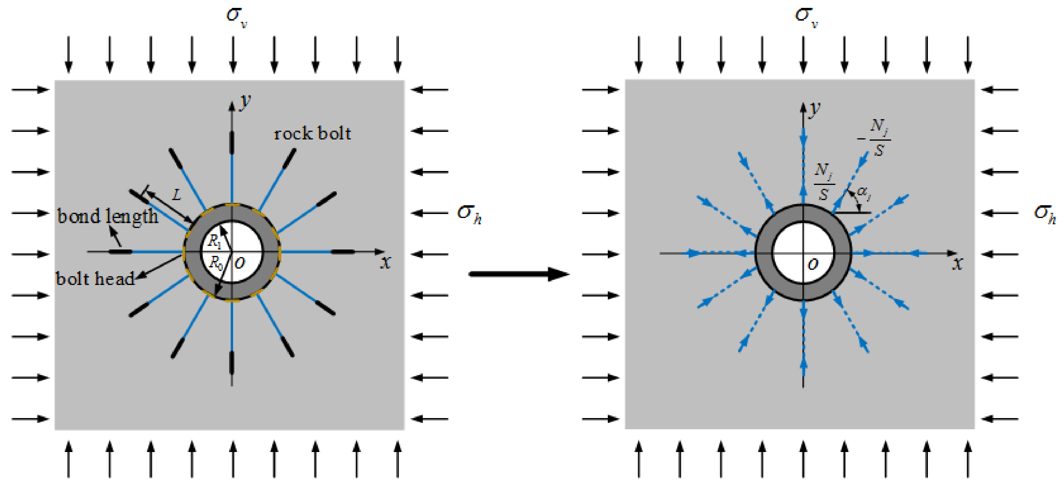
As shown in Figure 1, the model adopted in this paper firstly installs the point-anchored rock bolts perpendicular to the tunnel wall, and then lining support is applied. For the convenience of the analysis, it is assumed that the bolts and the lining are installed at the same time. After the bolts are installed, they will deform along with the surrounding rock. Compared with the scale of the surrounding rock, the influence of the rock bolt diameter can be ignored. Therefore, the interaction between the point-anchored rock bolts and the surrounding rock in a deeply buried circular tunnel is simplified to a plane strain problem, in which multiple pairs of concentrated forces act on the vicinity of a circular hole in an infinite domain.
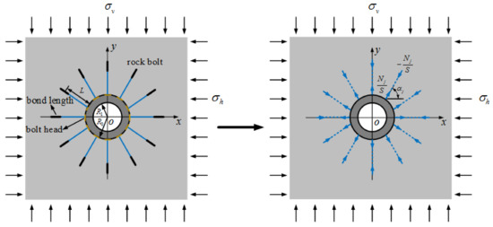
Figure 1.
The equivalent action of point-anchored rock bolts.
This paper assumes that the tunnel is deeply buried, that the rock mass, lining, and rock bolts are always in an elastic state under the in-situ stress, and the strain along the axis direction of the tunnel is zero. That is to say, it is a plane strain condition. The lining and surrounding rock are in complete contact, which means the contact stress and the displacement at their interface is continuous. In addition, the action positions of the concentrated forces are assumed to be at the two effective ends of the bolts, which are at the tunnel wall and the midpoint of the anchorage section.
2. Fundamental Principles and Equations
2.1. Two Analytic Functions Considering Lining Effect
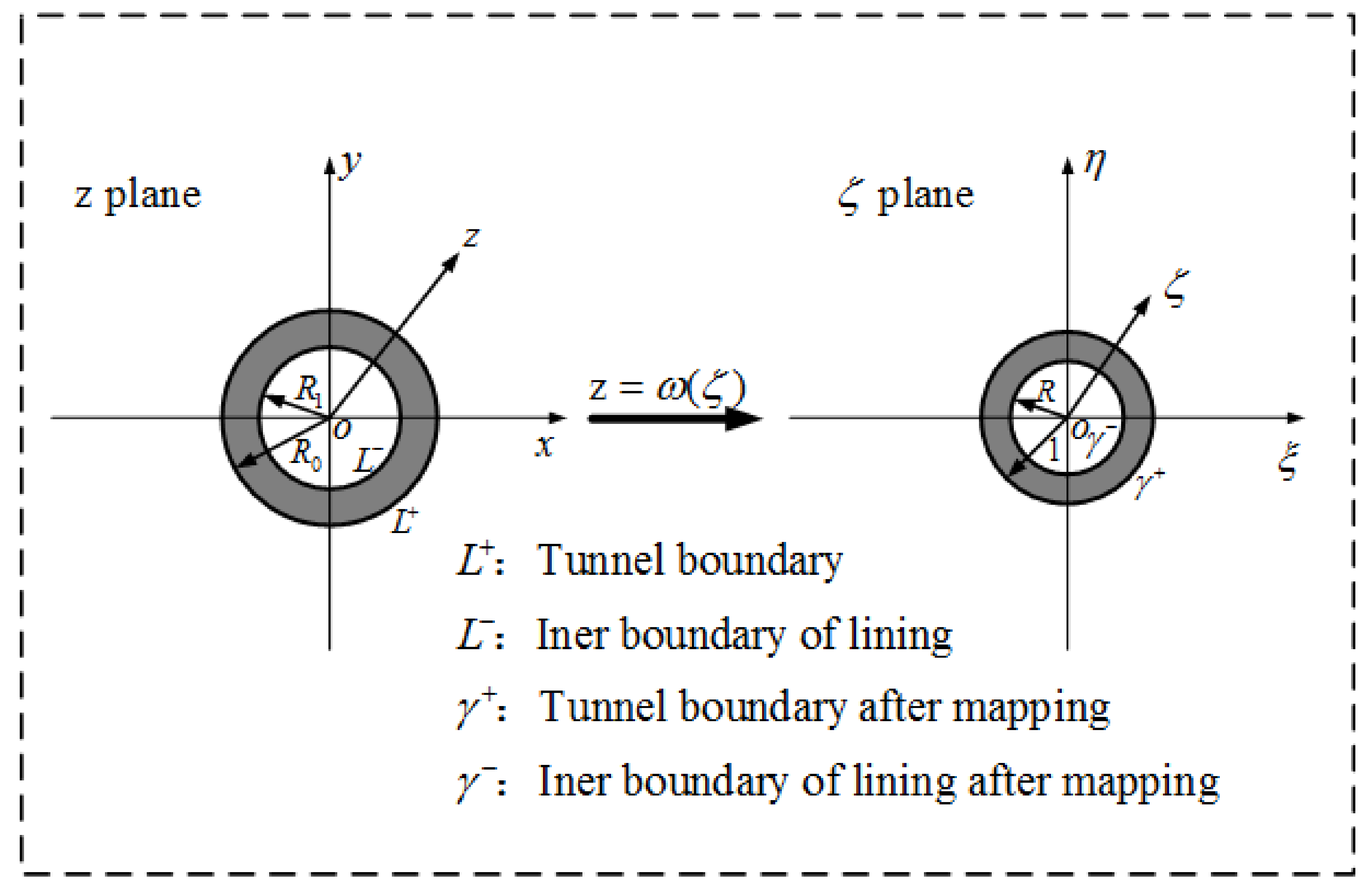
Firstly, the conformal transformation is adapted to map the lining and the outer area of the tunnel into a concentric circle and the outer area of a unit circle, respectively. See Figure 2. Moreover, the mapping function is as follows:
where R0 is the radius of the circular tunnel; ζ = ρeiθ and ζ = σ = eiθ (the tunnel boundary); i = ; ρ is the radius in the ζ plane, and ρ = r/R0, where r is the polar radius in the z plane; θ is the polar angle in the ζ plane, as is the polar angle in the z plane. The outer radius of the ring is set to 1 and the inner radius R is equal to R1/R0; R1 is the radius of the inner boundary of the lining. The inner and outer boundaries of the lining are indicated by L− and L+ in the plane, and γ-- and γ-+ in the ζ plane, respectively.
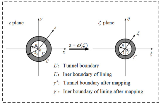
Figure 2.
Lined circular tunnel and mapped result.
After the application of the lining, the surrounding rock interacts with the lining. The two analytic functions representing the effect of the lining on the surrounding rock can be written as follows:
Correspondingly, the two analytic functions representing the effect of the surrounding rock on the lining can be written as follows:
The above a0, b0, d0, g0, ak, bk, ek, fk, pk, and qk are all real numbers to be determined. The series is taken as a finite term, i.e., Ne in this paper, and when Ne is large enough, the result is sufficiently accurate.
Using φ0(ζ), ψ0(ζ), φ1(ζ) and ψ1(ζ), the displacement of any point within the surrounding rock restricted by the lining and the displacements of any point within the lining due to the action of the surrounding rock can be solved as follows:
where and are the radial and tangential displacement components in the z plane, respectively, K1 = 3–4 μ1, K2 = 3–4 μ2; (μ1, G1, E1), (μ2, G2, E2) are Poisson’s ratio, shear modulus, and Young’s modulus of the rock mass and lining, respectively; and G1 = E1/[2(1 + m1)], G2 = E2/[2(1 + m2)].
2.2. Two Analytic Functions Considering Bolts Effect
After the rock bolts are installed into the rock mass, they will restrict deformation. Meanwhile, the bolts are stretched. As mentioned above, the effect of point-anchored rock bolts on the surrounding rock can be regarded as pairs of concentrated forces of equal magnitude acting in opposite directions along the length of the bolts. The analytic functions representing the action of the j-th concentrated force on the surrounding rock can be expressed as follows [22]:
where Xj, Yj respectively represent the component forces of the j-th concentrated force along the x and y axis; and cj is radius vector from the position of the concentrated force to the center of circle tunnel.
Based on the simplified bolts model, one of the concentrated forces acts outwards at the boundary of the tunnel, and the other acts inwards at the midpoint of the bond length (see Figure 1). Let Nj denote the axial force of the j-th rock bolt. Then, we have the following equations:
where αj is the j-th (j = 1, 2, …, n) rock bolt installment angle; n is the installation number of the point-anchored rock bolts; L is the length between the effective ends of the bolts; and S is the spacing of the rock bolts.
According to the superposition principle of elasticity, the analytic functions representing the effect of the point-anchored rock bolts on the surrounding rock is as follows:
Therefore, the displacements of any point within the surrounding rock caused by bolts is
where andare the radial and tangential displacement components, respectively. Combining Equations (6)–(11), the radial displacement can be written as
where
2.3. Two Analytic Functions Considering the Excavation of the Tunnel
The displacement and of any point within the surrounding rock mass caused by circular tunnel excavation can be obtained by two analytic functions [15]:
where and are the vertical and horizontal in situ stress, respectively.
2.4. Equations of Solving φ0(ζ), ψ0(ζ), φ1(ζ), ψ1(ζ) and Nj
2.4.1. Stress Condition of Inner Boundary of the Lining
Since no loads apply on the inner boundary of the lining L− the stress boundary conditions along γ-- can be written as
Substituting Equation (3) into Equation (16) leads to
After a comparison of the coefficients of σ--Ne→σ-Ne in Equation (17), the relationship of the coefficients can be obtained as follows:
2.4.2. Contact Stress Continuity Condition between Lining and Surrounding Rock
The lining and surrounding rock contact completely; therefore, the stress continuity conditions along the interface are met, which can be written as
Substituting Equations (2) and (3) into Equation (19) leads to
2.4.3. Displacement Compatibility Condition between Lining and Surrounding Rock
Similarly, because of the full contact between the surrounding rock and lining, we can obtain the following equation from the displacement compatibility condition:
where η is the displacement release coefficient [12,13,14], which can describe the support time, based on the distance from the working face to the lined section.
Substituting Equations (4), (5), (11), and (15) into Equation (21), and, through sorting, we have
where
Moreover, the influence caused by the lining on the surrounding rock drops when ζ increases, namely, when ζ, and . Therefore, the following relationship can be obtained:
Since , , and , according to Equation (26), we have
2.4.4. Displacement Compatibility Condition between Bolts and Surrounding Rock
Due to the excavation of the tunnel, point-anchored rock bolts interact with the surrounding rock. Before the failure of the bolts, the points of connection (the bolt head and midpoint of the anchorage section) between the surrounding rock and the adjacent bolts will always be bonded and deform together. Based on the displacement compatibility condition, we have
where (δ) is the elongation of the δ-th rock bolt, which can be calculated as follows:
where E3, d represent the Young’s modulus and the diameter of the rock bolt, respectively.
By combining Equations (2), (4), (12)–(15), (28), and (29), the displacement compatibility condition between the rock bolt and the rock mass can be obtained as follows:
To solve φ0(ζ), ψ0(ζ), φ1(ζ), ψ1(ζ) and Nj(j = 1, 2, …, n), 6Ne + 4 + n unknown numbers need to be solved, a0, ak, b0, bk, d0, ek, fk, g0, pk, qk (k = 1, 2, …, Ne) as does Nj(j = 1, 2, …, n). Accordingly, 6Ne + 4 + n linear equations can be established, i.e., 2Ne + 1 linear equations describing the stress condition of the inner boundary of the lining in Equation (18), 2Ne + 1 linear equations describing the contact stress condition on the interface between the lining and the surrounding rock in Equation (20), linear equations based on the displacement compatibility condition of the interface between the lining and the surrounding rock in Equation (22) (θ = 2kπ/(2Ne + 1), (k = 1, 2, …, 2Ne + 1) respectively, (avoid being too close to the anchor head), one linear equation describing the influence of the lining on the surrounding rock at infinity in Equation (27), and n linear equations describing the displacement compatibility condition between the bolts and the surrounding rock in Equation (30) (let δ be equal to 1, 2, …, n, respectively).
2.5. Stress and Displacement within Lining and Surrounding Rock
After φ0(ζ), ψ0(ζ), φ1(ζ) and ψ1(ζ) are derived, with given values of R0, R1, E1, E2, E3, d, L, n, η, σv, σh, μ1, μ2, Ne, S, the stress and displacement within the lining and surrounding rock can be solved.
2.5.1. Stress and Displacement Components in the Lining
2.5.2. Stress and Displacement within Surrounding Rock
The stress components of any point within surrounding rock are as follows:
where
Γ = (σv + σh)/4 and Γ′ = (σv−σh)/2. Γω(ζ) and Γ′ω(ζ) are the analytic functions before excavation, and the remaining terms represent the actions caused by the lining, bolts, and tunnel excavation, respectively.
3. Comparison with Numerical Solution
Twelve bolts were installed every 30 degrees. The relevant parameters are listed in the following.
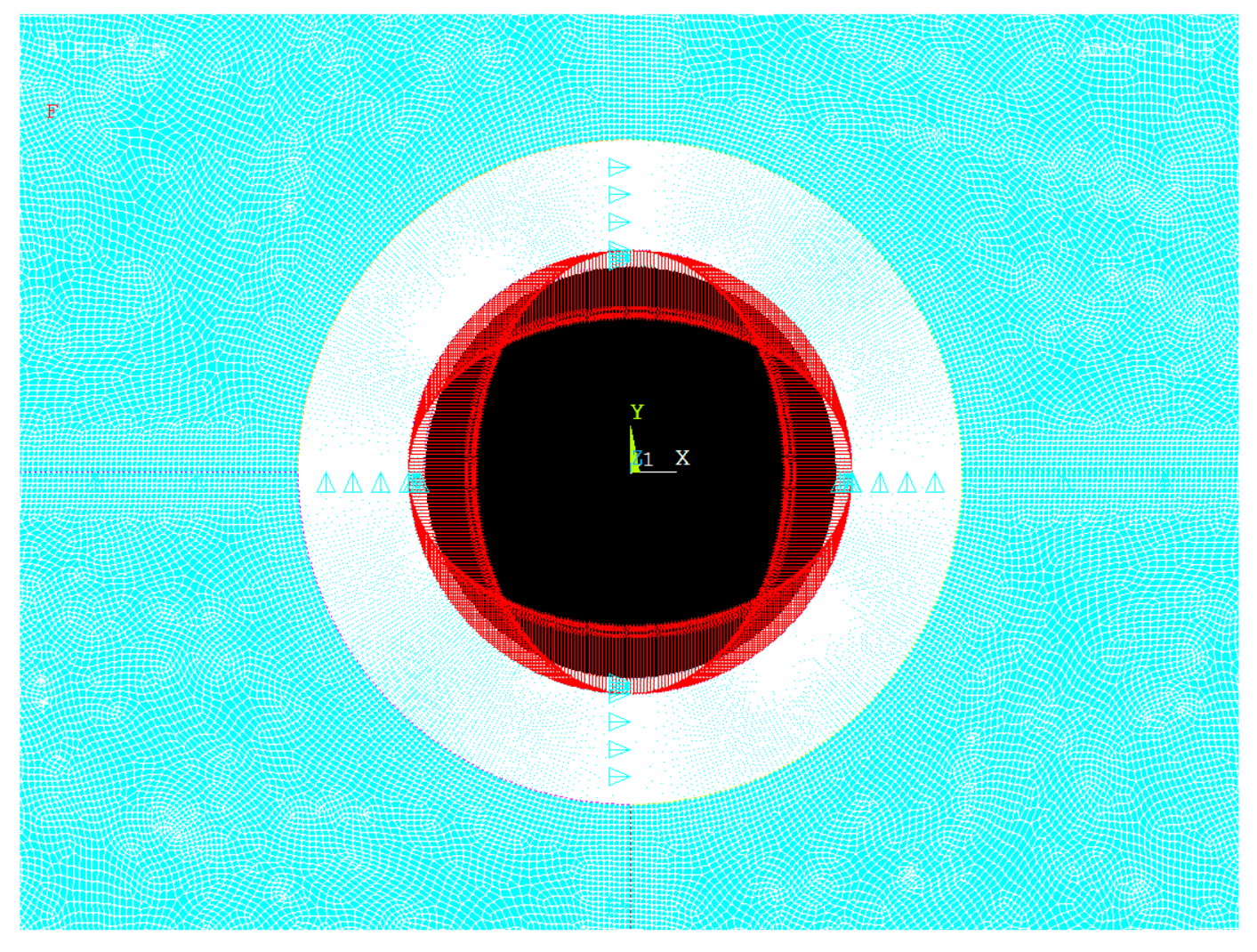
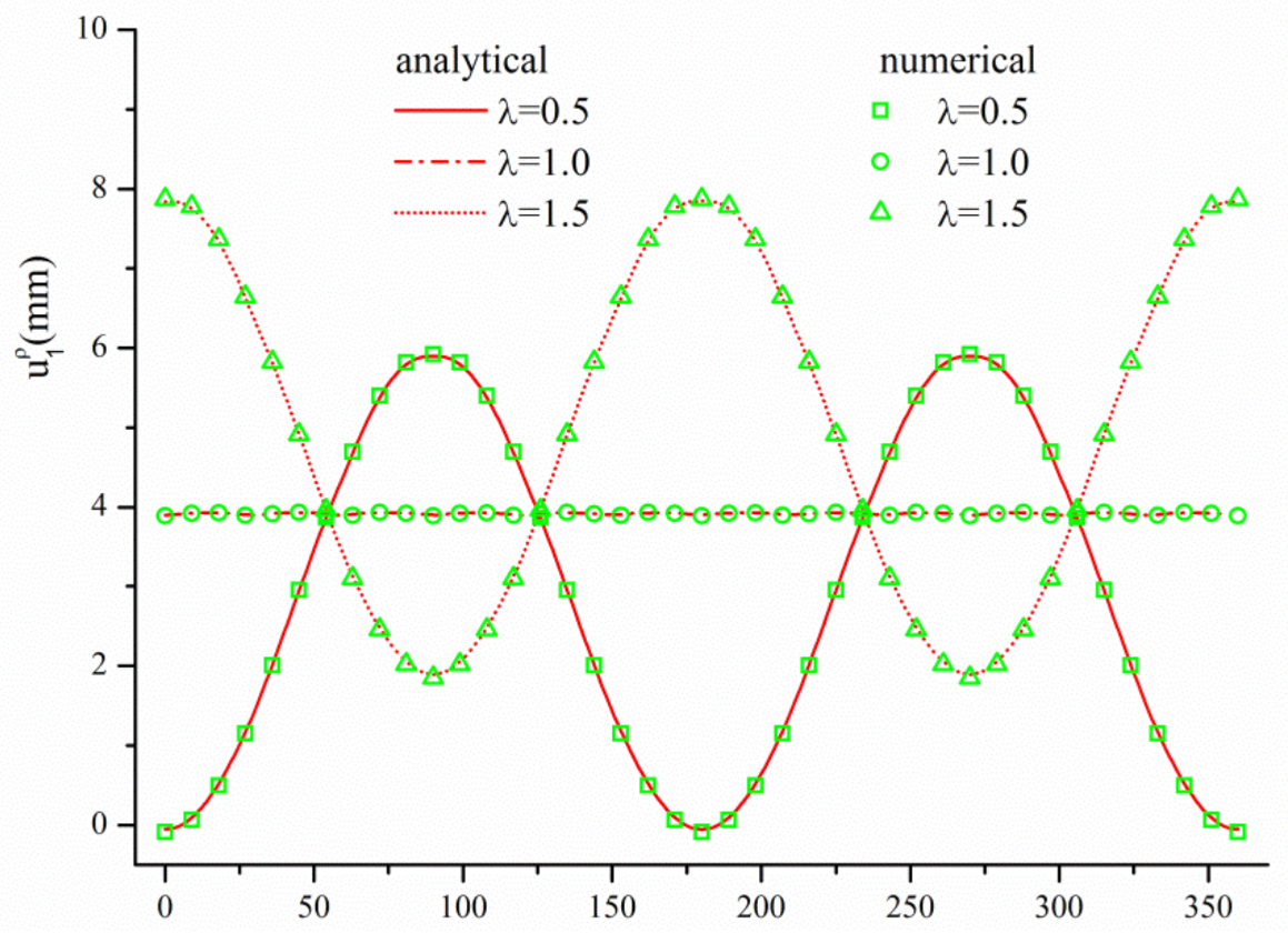
The numerical solution was calculated with ANSYS. The size of the model was , the lining and rock mass were simulated using the Plane42 element (2D entity unit) with different material properties, as shown in Table 1, the point-anchored rock bolts were simulated using the Combin14 element (spring unit), and the contact relationship between the lining and the surrounding was simulated using the targe169 and contac171 elements, which is able to set different contact relationships through options such as complete contact. The boundary condition was to limit the displacement of the symmetry axis of the model in the x and y directions, respectively. The process of tunnel excavation was simulated through the “stress release method” proposed by Duncan and Dunlop [37]. In addition, Hooke’s law was adopted as the constitutive model in this paper. Figure 3 shows the numerical model. Figure 4, Figure 5 and Figure 6 show a comparison of the analytical and numerical solutions, including the axial forces of bolts, tangential stresses, and radial displacements of points at the inner boundary of the lining. λ = σv/σh is the coefficient of lateral pressure. The compressive stress and the displacement toward to hole were positive.

Table 1.
The values of relevant parameters.
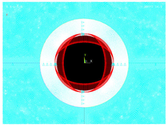
Figure 3.
The ANSYS model of circular tunnel with support.
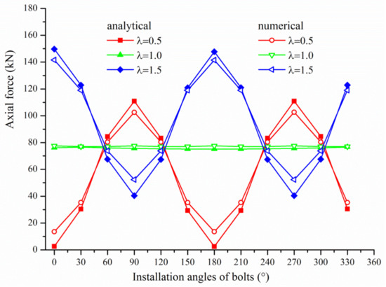
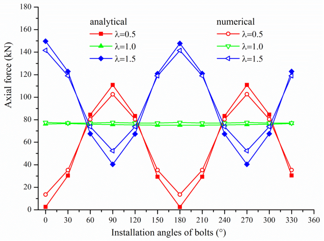
Figure 4.
A comparison of axial forces of the bolts.
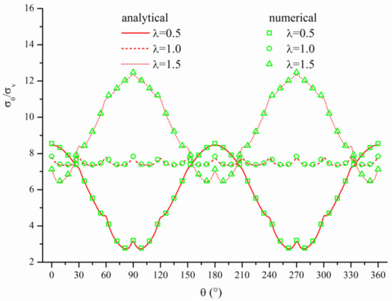
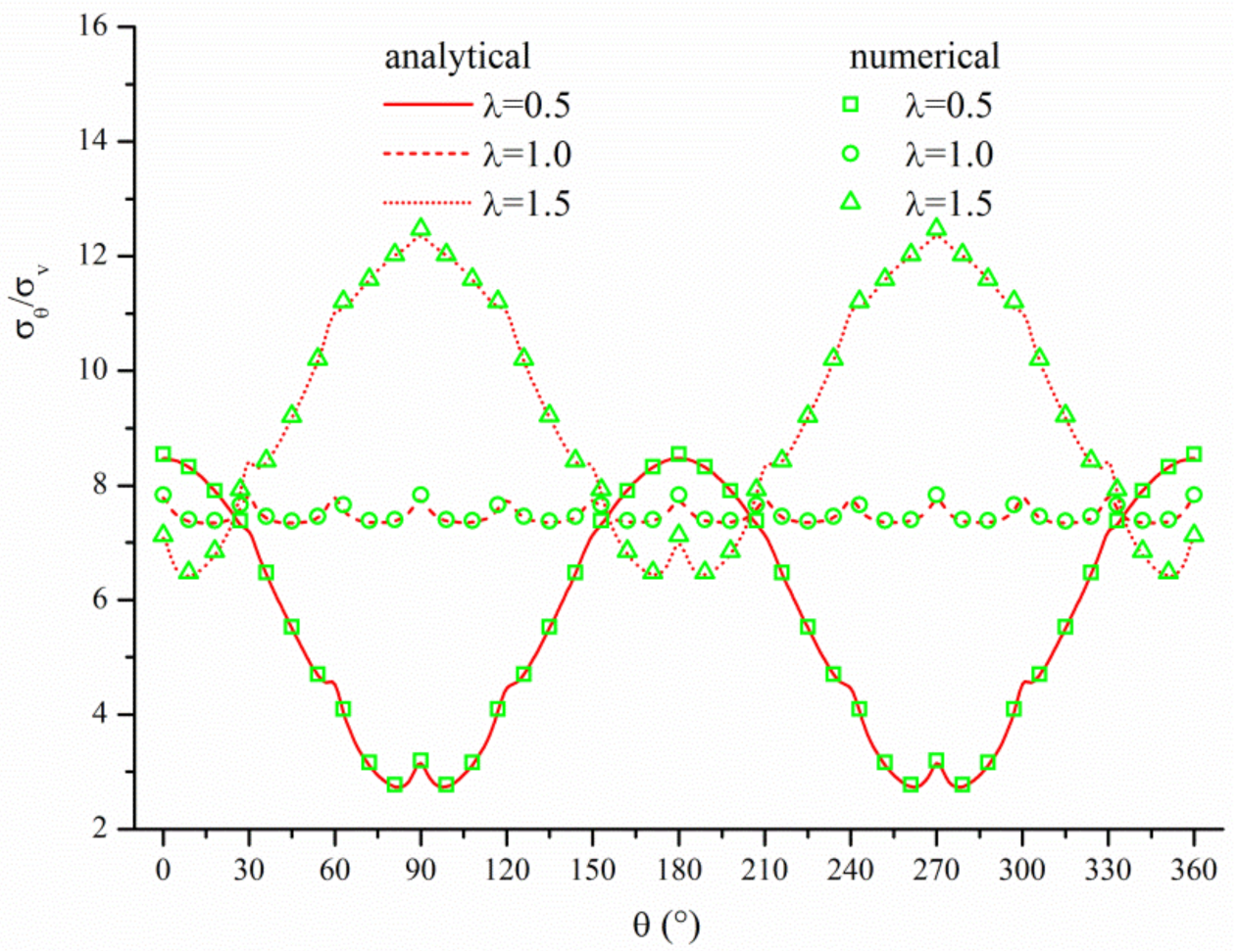
Figure 5.
A comparison of tangential stresses of points at the inner boundary of the lining.
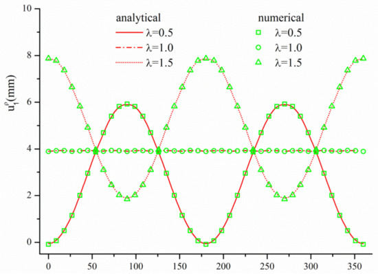
Figure 6.
A comparison of radial displacements of points at the inner boundary of the lining.
It can be seen from the Figure 4 that the axial force distribution of the bolts obtained by the proposed method was in line with the actual laws, i.e., the maximum axial force was reached when the bolt was installed along the direction of the maximum in situ stress because of maximum deformation and the axial forces of the bolts were the same at different angles when λ = 1. As compared with the numerical solution, there were only marginal differences along the direction of minimum in situ stress when λ = 0.5 and λ = 1.5, and the numerical solution was larger. In addition, they were almost equal when λ = 1, and only at certain angles was the numerical solution slightly larger. As for the tangential stress and the radial displacement of the point at the inner boundary of the lining, as shown in Figure 5 and Figure 6, the analytical solution almost coincided with the numerical solution. Therefore, to a large extent, the effectiveness of this model is proved.
4. Examples and Parameter Analysis
4.1. The Effect of Bolts on the Lining
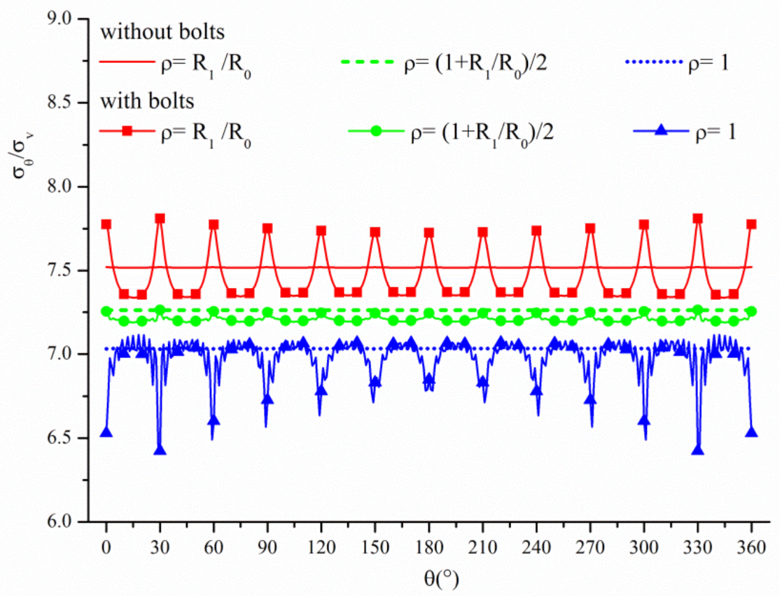
If we adopt the values in Section 3 with λ = 1, we can call it ‘with bolts’. As long as the Young’s modulus of point-anchored rock bolts is equal to that of the rock mass, the effect of the bolts will be erased, which we call ‘without bolts’. Then, the tangential stresses and radial displacements of the points within the lining at ρ = R1/R0 (L−), ρ = (R1/R0 + 1)/2(the middle of the lining), and ρ = 1 (L+) can be plotted as follows.
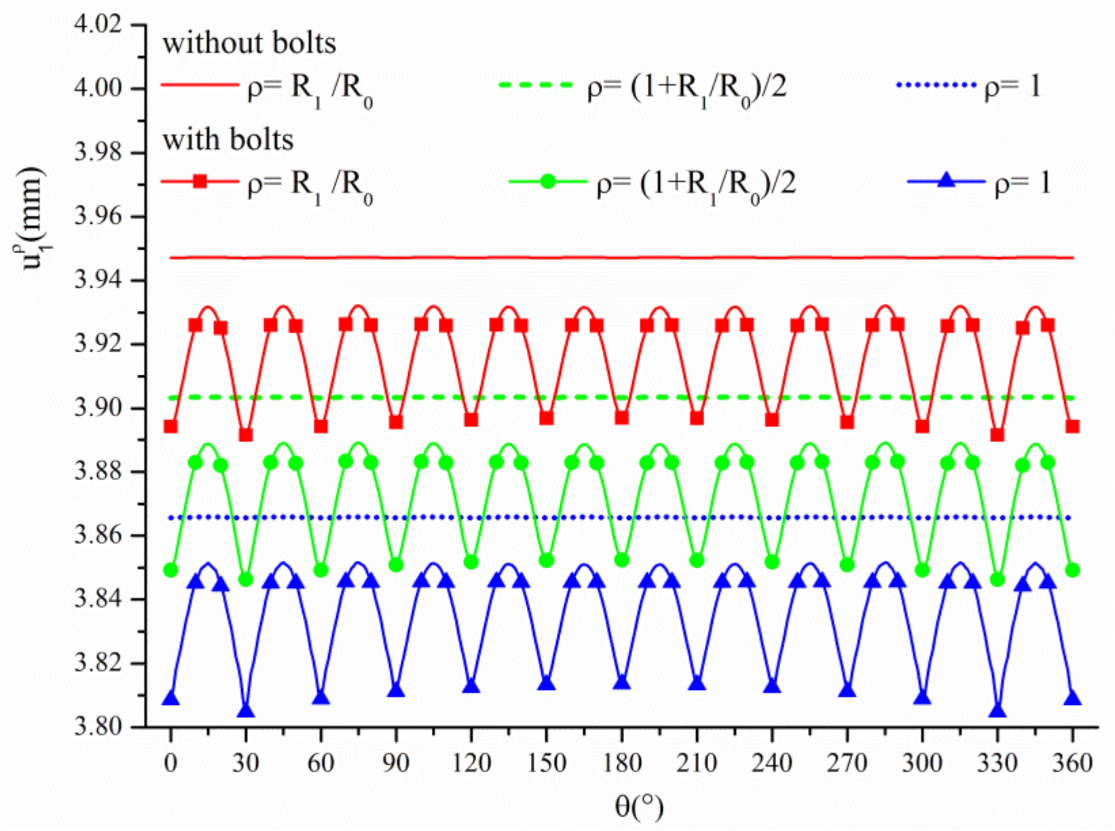
In Figure 7, the three lines are the tangential stresses of the points within the lining without bolts, while the three lines with symbols are the tangential stresses with bolts. This shows that the stress distribution in the lining changed and was not uniform because of the bolts, i.e., for most of the points at the inner boundary of the lining, their tangential stresses were reduced by about 2.23% compared with the without bolts scenario; however, for the points within 4° from the bolts, their tangential stresses increased rapidly, even exceeding the value without bolts, and the maximum amplitude reached 3.72%. Conversely, the law was opposite for the points at the outer boundary of the lining, i.e., the tangential stresses in the direction of the bolts sharply decreased, and the maximum amplitude reached 8.68%. In addition, for the point in the middle of the lining, the tangential stresses were slightly smaller than in the scenario without bolts, but increased in the direction of the bolts, with a small amplitude. As for the radial displacement comparison in Figure 8, it can be seen that, at any point on the inner, the middle, or the outer boundary of the lining, the radial displacements decreased, especially in the direction of bolt installation.
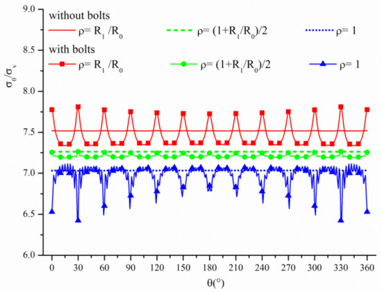
Figure 7.
The effect of bolts on the tangential stress of the lining.
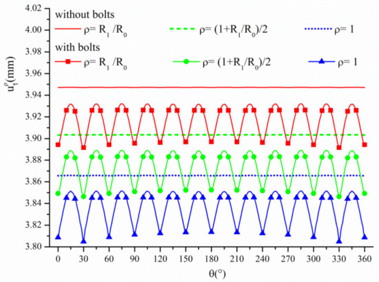
Figure 8.
The effect of bolts on the radial displacement of the lining.
4.2. The Effect of Young’s Modulus of the Lining
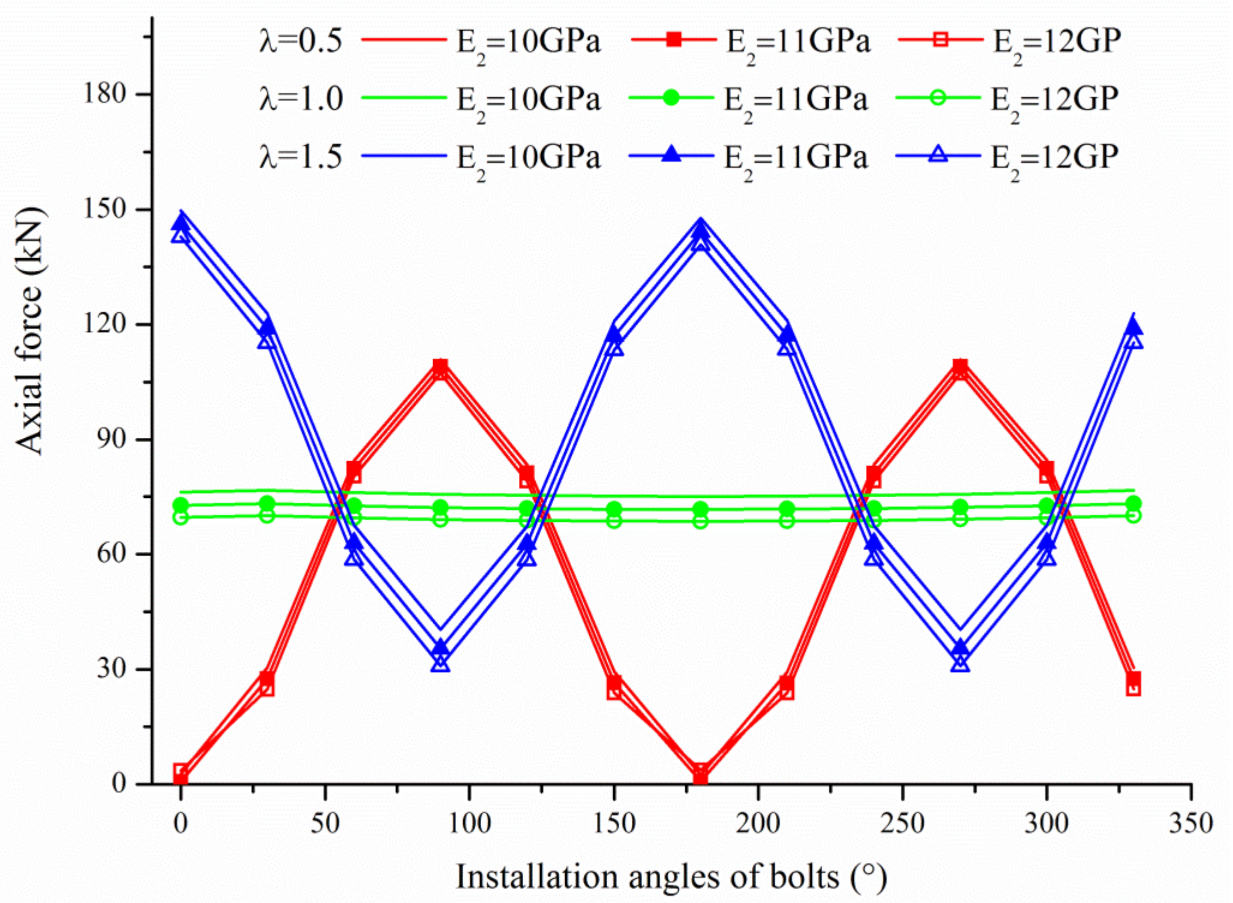
Let the Young’s modulus of the lining E2 = 10 GPa, 11 GPa, and 12 GPa, respectively. Then, by adopting the proposed approach, the axial forces of the bolts at different angles and the tangential stresses for the points at L− can be plotted as follows.
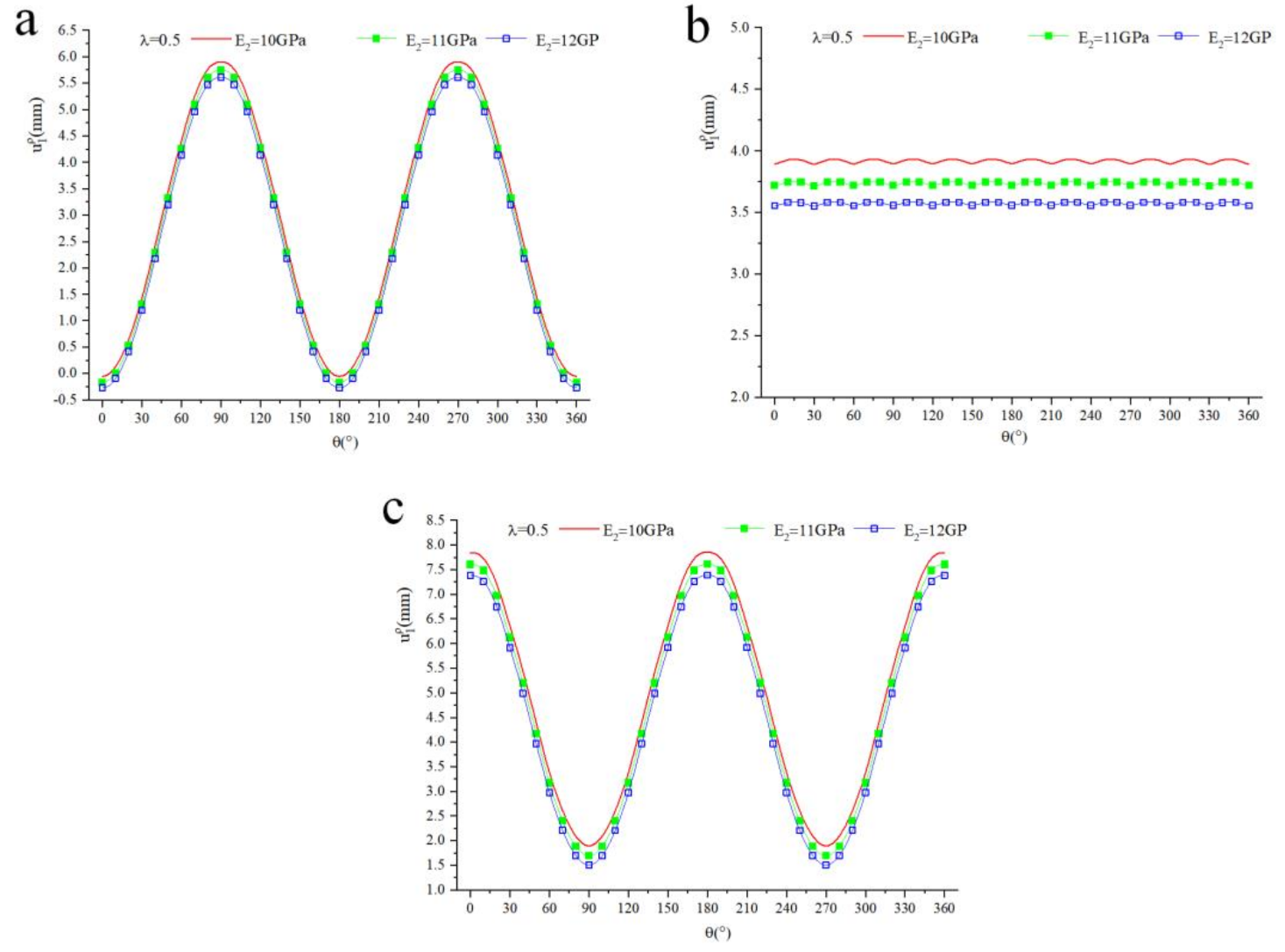
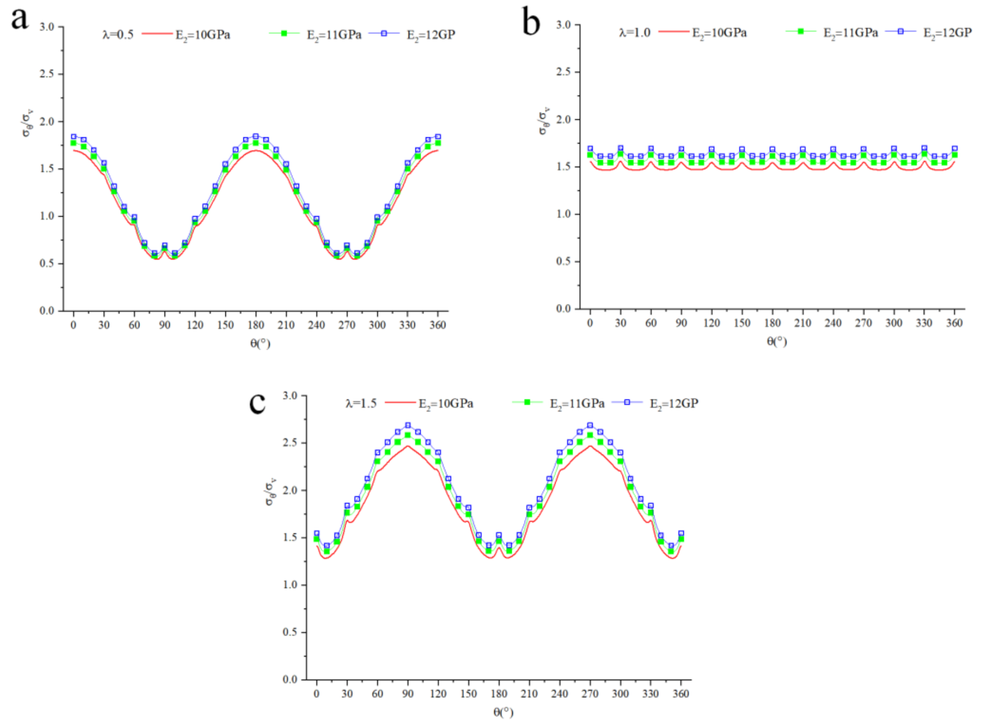
It can be seen from the Figure 9 that regardless of the value of λ, the axial forces of the bolts dropped with the increase in the Young’s modulus of the lining E2. This law is the same with the radial displacement for the points at the inner boundary of the lining with different E2 in Figure 10. While the tangential stresses were different, they increased with the increase in E2, as shown in Figure 11. These results are consistent with the engineering reality.
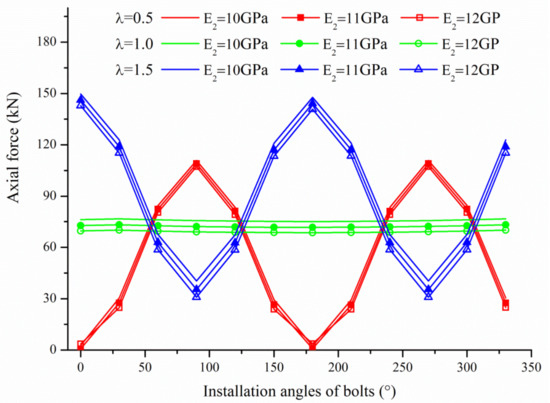
Figure 9.
Axial forces of the bolts with different E2.
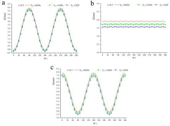
Figure 10.
Radial displacement for the points at L− with different E2 ((a) λ = 0.5, (b) λ = 1.0, (c) λ = 1.5).
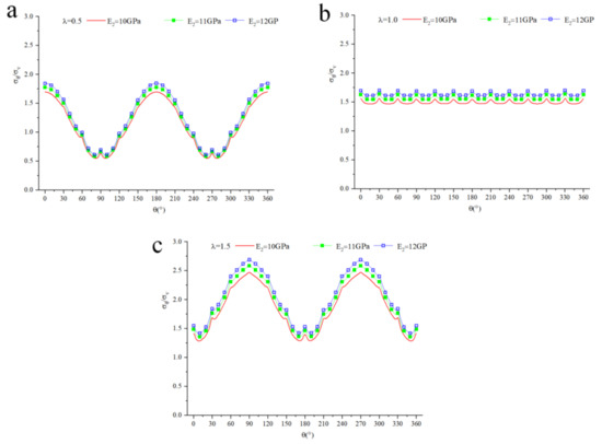
Figure 11.
Tangential stresses for the points at L− with different E2 ((a) λ = 0.5, (b) λ = 1.0, (c) λ = 1.5).
5. Conclusions
A mechanical model for a deeply buried circular tunnel jointly supported by lining and point-anchored rock bolts is proposed using the complex function method. They are linked together based on the complete contact condition between the lining and the surrounding rock, and the displacement coordination condition between the point-anchored rock bolts and the surrounding rock. We established these relationships using the analytic functions. This allowed us to establish relevant linear equations for calculating the analytic function coefficients and the axial forces of the bolts. Then, we used the analytic functions obtained to calculate the stress and displacement at any point within the lining and surrounding rock. The results are in accordance with the engineering reality and compared well with the numerical solution.
Thereafter, the effect of the bolts on the lining and the influence of Young’s modulus of the lining on the whole supporting system was explored. The following conclusions were drawn: (1) The installation of point-anchored rock bolts changes the stress distribution of the lining, and reduces the tangential stresses for most points within the lining (not significant); however, there are different behaviors for the points in the direction of the bolts, i.e., tangential stresses at the inner boundary of the lining sharply increase and even exceed the value observed without bolts, while tangential stresses at the outer boundary of the lining sharply drop. The radial displacement decreases regardless of the point, especially in the direction of bolt installation; (2) with the increase in the Young’s modulus of the lining, the axial forces of the bolts and displacement at the inner boundary of the lining decrease, while the tangential stresses for the points at the inner boundary of the lining increase, which means it can bear increased loads.
Author Contributions
Conceptualization, A.L. and Y.L.; methodology, Y.L.; software, Y.L.; validation, H.C.; formal analysis, Y.L.; writing—original draft preparation, Y.L.; writing—review and editing, Y.L.; supervision, A.L.; funding acquisition, A.L. All authors have read and agreed to the published version of the manuscript.
Funding
This research was funded by [National Natural Science Foundation of China] grant number [51974124].
Institutional Review Board Statement
The study was conducted in accordance with the Declaration of Helsinki, and approved by the Institutional Review Board.
Informed Consent Statement
Informed consent was obtained from all subjects involved in the study.
Conflicts of Interest
The authors declare no conflict of interest.
References
- Leca, E.; Clough, G.W. Preliminary design for NATM tunnel support in soil. J. Geotech. Eng. 1992, 118, 558–575. [Google Scholar] [CrossRef]
- Dasari, G.R.; Bolton, M.D. Numerical modelling of a NATM tunnel construction in London Clay. In Proceedings of the International Symposium on Geotechnical Aspects of Underground Construction in Soft Ground, London, UK, 15–17 April 1996. [Google Scholar]
- Karakus, M.; Fowell, R.J. FEM analysis for the effects of the NATM construction technique on settlement above shallow soft ground tunnels. Educ. Res. 2000, 22, 31–33. [Google Scholar]
- Pichler, C.; Lackner, R.; Martak, L.; Mang, H.A. Optimization of jet-grouted support in NATM tunnelling. Int. J. Num. Anal. Met. Geomech. 2004, 28, 781–796. [Google Scholar] [CrossRef]
- De Farias, M.M.; Júnior, Á.H.M.; de Assis, A.P. Displacement control in tunnels excavated by the NATM: 3-D numerical simulations. Tunn. Undergr. Space Technol. 2004, 19, 283–293. [Google Scholar] [CrossRef]
- Schuller, H.; Schweiger, H.F. Application of a multilaminate model to simulation of shear band formation in NATM-tunnelling. Comput. Geotech. 2002, 29, 501–524. [Google Scholar] [CrossRef]
- Prazeres, P.G.C.; Thoeni, K.; Beer, G. Nonlinear analysis of NATM tunnel construction with the boundary element method. Comput. Geotech. 2012, 40, 160–173. [Google Scholar] [CrossRef]
- Ren, M.Y.; Zhang, Q.Y.; Zhang, Z.J.; Zhang, L.-Y.; Gao, Q. Study on mechanism of segmental lining-bolt combined support for deep-buried tunnel. Geotech. Geol. Eng. 2019, 37, 3649–3671. [Google Scholar] [CrossRef]
- Bulychev, N.S. Underground Construction Mechanics; Nedra: Moscow, Russia, 1982. (In Russian) [Google Scholar]
- Atkinson, C.; Eftaxiopoulos, D.A. A plane model for the stress field around an inclined, cased and cemented wellbore. Int. J. Numer. Anal. Meth. Geomech. 1996, 20, 549–569. [Google Scholar] [CrossRef]
- Wang, M.B.; Li, S.C. A complex variable solution for stress and displacement field around a lined circular tunnel at great depth. Int. J. Numer. Anal. Meth. Geomech. 2009, 33, 939–951. [Google Scholar] [CrossRef]
- Lu, A.Z.; Zhang, L.Q.; Zhang, N. Analytic stress solutions for a circular pressure tunnel at pressure and great depth including support delay. Int. J. Rock Mech. Min. Sci. 2011, 48, 514–519. [Google Scholar] [CrossRef]
- Lu, A.Z.; Zhang, N.; Kuang, L. Analytic solutions of stress and displacement for a non-circular tunnel at great depth including support delay. Int. J. Rock Mech. Min. Sci. 2014, 70, 69–81. [Google Scholar] [CrossRef]
- Lu, A.Z.; Zhang, N.; Qin, Y. Analytical solutions for the stress of a lined non-circular tunnel under full-slip contact conditions. Int. J. Rock Mech. Min. Sci. 2015, 79, 183–192. [Google Scholar] [CrossRef]
- Lu, A.Z.; Zhang, L.Q. Complex Function Method on Mechanical Analysis of Underground Tunnel; Science Press: Beijing, China, 2007. [Google Scholar]
- Muskhelishvili, N.I. Some Basic Problems of the Mathematical Theory of Elasticity; Noordhoff: Groningen, The Netherlands, 1963. [Google Scholar]
- Hoek, E.; Brown, E.T. Underground Excavations in Rock; The Institution of Mining and Metallurgy: London, UK, 1982. [Google Scholar]
- Li, C.; Stillborg, B. Analytical models for rock bolts. Int. J. Rock Mech. Min. Sci. Abstr. 1999, 36, 1013–1029. [Google Scholar] [CrossRef]
- Chen, S.H.; Qiang, S.; Chen, S.F.; Egger, P. Composite element model of the fully grouted rock bolt. Rock Mech. Rock Eng. 2004, 37, 193–212. [Google Scholar] [CrossRef]
- Cai, Y.; Esaki, T.; Jiang, Y. A rock bolt and rock mass interaction model. Int. J. Rock Mech. Min. Sci. 2004, 41, 1055–1067. [Google Scholar] [CrossRef]
- Cai, Y.; Esaki, T.; Jiang, Y. An analytical model to predict axial load in grouted rock bolt for soft rock tunneling. Tunn. Undergr. Space Technol. 2004, 19, 607–618. [Google Scholar] [CrossRef]
- Lu, A.Z.; Liu, Y.J.; Zhang, X.L. A theoretical solution for a circular tunnel reinforced by fully grouted rock bolt. Chin. J. Rock Mech. Eng. 2018, 37, 1561–1573. [Google Scholar] [CrossRef]
- Lu, A.Z.; Zhu, E.H. An analytical method for determining the axial force of point anchored rockbolts in an elliptical tunnel. Chinese J. Rock Mech. Eng. 2019, 38, 1117–1128. [Google Scholar] [CrossRef]
- Farmer, I.W. Stress distribution along resin grouted rock anchor. Int. J. Rock Mech. Min. Sci. 1975, 12, 347–351. [Google Scholar] [CrossRef]
- Freeman, T.J. The behaviour of fully-bonded rock bolts in the Kielder experimental tunnel. Tunn. Tunn. 1978, 10, 37–40. [Google Scholar] [CrossRef]
- Bjurstrom, S. Shear strength of hard rock joints reinforced by grouted untensioned bolts. Pro. 3rd ISRM Congr. Denver 1974, 2, 1194–1999. [Google Scholar]
- Benmokrane, B.; Chennouf, A.; Mitri, H.S. Laboratory evaluation of cementbased grouts and grouted rock anchors. Int. J. Rock Mech. Min. Sci. Geomech. Abstr. 1995, 32, 633–642. [Google Scholar] [CrossRef]
- Bernaud, D.; Buhan, P.D.; Maghous, S. Numerical simulation of the convergence of a bolt-supported tunnel through a homogenization method. Int. J. Numer. Anal. Methods Geomech. 1995, 19, 267–288. [Google Scholar] [CrossRef]
- Wong, H.; Trompille, V.; Dias, D. Extrusion analysis of a bolt-reinforced tunnel face with finite ground-bolt bond strength. Can. Geotech. J. 2004, 41, 326–341. [Google Scholar] [CrossRef]
- Wong, H.; Trompille, V.; Dias, D. Displacement behaviour of a bolt-reinforced tunnel face with finite ground-bolt bond strength: Analytical and numerical approaches, in situ data. J. Ecol. 2014, 102, 1549–1561. [Google Scholar] [CrossRef]
- Bobet, A. A simple method for analysis of point anchored rockbolts in circular tunnels in elastic ground. Rock Mech. Rock Eng. 2006, 39, 315–338. [Google Scholar] [CrossRef]
- Chen, S.H.; Fu, C.H.; Isam, S. Finite element analysis of jointed rock masses reinforced by fully-grouted bolts and shotcrete lining. Int. J. Rock Mech. Min. 2009, 46, 19–30. [Google Scholar] [CrossRef]
- Holmgren, J.; Ansell, A. Design of Bolt Anchored Reinforced Shotcrete Linings Subjected to Impact Loadings. In Proceedings of the 10th International Conference on Shotcrete for Underground Support, Whistler, BC, Canada, 12–16 September 2012. [Google Scholar]
- Sun, Y.; Zhang, D.L. Synergy principle of complex supporting structural systems in tunnels. Eng. Mech. 2016, 33, 52–62. [Google Scholar] [CrossRef]
- Bieniawski, Z.T. Engineering Rock Mass Classification; John Wiley and Sons: New York, NY, USA, 1989. [Google Scholar]
- Barton, N.R.; Lien, R.; Lunde, J. Engineering classification of rock masses for the design of rock support. Rock Mech. 1974, 6, 189–236. [Google Scholar] [CrossRef]
- Duncan, J.M.; Dunlop, P. Slopes in Stiff-fissured Clays and Shales. J. Soil Mech. Found. Div. 1968, 95, 467–492. [Google Scholar] [CrossRef]
Publisher’s Note: MDPI stays neutral with regard to jurisdictional claims in published maps and institutional affiliations. |
© 2022 by the authors. Licensee MDPI, Basel, Switzerland. This article is an open access article distributed under the terms and conditions of the Creative Commons Attribution (CC BY) license (https://creativecommons.org/licenses/by/4.0/).