Abstract
In this paper, a high-gain THz antenna array is presented. The array uses a polyimide substrate with a thickness of 10 m, a relative permittivity of 3.5, and an overall volume of 2920 m × 1055 m × 10 m, which can be employed for THz band space communication and other interesting applications. The dual-band single-element antenna is designed in four steps, while operating at 0.714 and 0.7412 THz with −10 dB bandwidths of 4.71 and 3.13 GHz, providing gain of 5.14 and 5 dB, respectively. In order to achieve a high gain, multiple order antenna arrays are designed such as the 2 × 1 antenna array and the 4 × 1 antenna array, named type B and C, respectively. The gain and directivity of the proposed type C THz antenna array are 12.5 and 11.23 dB, and 12.532 and 11.625 dBi at 0.714 and 0.7412 THz, with 99.76 and 96.6% radiation efficiency, respectively. For justification purposes, the simulations of the type B antenna are carried out in two simulators such as the CST microwave studio (CSTMWS) and the advance design system (ADS), and the performance of the type B antenna is compared with an equivalent circuit model on the bases of return loss, resulting in strong agreement. Furthermore, the parametric analysis for the type C antenna is done on the basis of separation among the radiating elements in the range 513 to 553 m. A 64 × 1 antenna array is used to achieve possible gains of 23.8 and 24.1 dB, and directivity of 24.2 and 24.5 dBi with good efficiencies of about 91.66 and 90.35% at 0.7085 and 0.75225 THz, respectively, while the 128 × 1 antenna array provides a gain of 26.8 and 27.2 dB, and directivity of 27.2 and 27.7 dBi with good efficiency of 91.66 and 90.35% at 0.7085 and 0.75225 THz, respectively. All the results achieved in this manuscript ensure the proposed design is a feasible candidate for high-speed and free space wireless communication systems.
1. Introduction
Developments in the field of wireless communication, Satellite Communication (SatCom), and radio astronomy have led us towards the utilization of THz bands due to the unavailability of large bandwidth in GHz spectrum and high-data-rate demand by consumers [1]. Data traffic is exponentially increasing due to abrupt variations in data generation and transmission by today’s society [2]. That is why the terahertz (THz) frequency bands, i.e., from 0.1 to 10 THz, especially from 0.1 to 1 THz, have attracted a great deal of interest in the fast few years due to ITU recommendations [3,4,5], advancements in THz technology, the availability of a wide unused bandwidth, and high data rate facilities [6]. ITU has reported a few bands from 0.1–1 THz for spectroscopy, radio astronomy, satellite communication, and space research [3,4,5]. Electromagnetic waves at THz frequency bands may also offer some other applications such as remote area communication, remote detection, clinical findings, radio cosmology, etc. [6].
Nonetheless, THz waves suffer from high attenuation due to atmospheric particles, such as water and gas molecules around the earth’s surface [7,8,9,10,11]. In the case of free space communication with minimal attenuation loss and a reliable communication link, a few design contemplations are needed for the wireless communication antenna, such as a high-gain antenna with maximum data rate capacity, and high directivity [3]. In space, the THz wave antenna is a suitable candidate for any application [12]. A high-gain THz antenna is required especially for satellite communication [3], and according to ITU recommendations for satellite communication, radio astronomy, and spectroscopy, a THz antenna will require minimum directivity of 24 dBi for space communication [5]. Various antenna models were reported in the past for satellite communication (SatCom); all of them were highly directive. The most popular antennas used for these services were either a wire, or a horn antenna with a parabolic reflector, while operating at GHz bands; these THz antenna were either linear, circular, or elliptical polarized [13]. However, these models face some limitations at THz bands, such as structural complexities and getting overheated [14,15,16,17,18]. Present-day progress in super-high-speed terahertz (THz) communication systems demands low cost, a low profile, and exceptionally efficient antenna design [6] with high directivity, to overcome propagation loss at THz bands ranging from 0.1 to 10 THz [3,4,5]. The microstripe or planar antenna is the most suitable candidate antenna among the existing antenna models for overcoming these limitations [19] due to the easy fabrication and integration of the planar antenna with micro scale devices as compared to the millimeter scale horn antenna. The THz planar antennas are small in terms of the micrometer scale, but their operations at THz bands cause problems, such as low gain and low bandwidth [20].
Despite the fact that the planar antenna has low gain and directivity, it is still used in multiple fields because high directivity can be achieved by utilizing multiple methods, such as antenna array, PBG-based antenna, and the reflector method [21,22]. However, the array technique is a suitable candidate that provides maximum gain and directivity as compared to other techniques [23]. The use of the antenna array can provide many benefits in different working conditions, such as the control of electromagnetic radiations and the provision of high directivity [24]. For wireless communication in the THz frequency band, many papers were reported in the literature, such as in [25], where the authors presented a cassegrain-based horn antenna that provides a high gain of 25 dB at 0.3 GHz, but the size of the antenna was not small. Similarly, the authors in [26] reported a 15-element antenna array providing directivity and radiation efficiency of 11.71 dBi and 70.8%, respectively, while operating at 0.3 THz. Similarly, the authors in [27] presented a PBG-based microstrip patch array antenna operating at 0.6 THz and providing gain, directivity, and radiation efficiency of 16.88 dBi, 17.19 dBi, and 89.72%, respectively.
However, the authors of [28] presented a PBG-based microstrip patch antenna array while operating at 0.65 THz and providing gain and radiation efficiency of 11.60 dB and 86.75%, respectively In addition to it, a high-gain Terahertz microstrip antenna array was proposed while operating at 0.1169 THz and providing gain, directivity, and radiation efficiency of 19.6 dB, 21.6 dBi and 67%, respectively [29]. Furthermore, the authors in [30] presented work on a graphene-based microstrip patch antenna array, working at 0.8883 THz and offering gain, directivity, and radiation efficiency of 14.6 dB, 15.5 dBi, and 83.67%, respectively. Similarly, the authors of [31] reported a Sub-THz 4 × 1 array antenna, operating at 0.3 THz and providing gain and efficiency of 13.6 dB and 89%, respectively. According to the work presented in [25,26,27,28,29,30,31,32,33,34,35,36,37], all the authors attempted to present a THz antenna, but they were not able to present a high-gain antenna with wide bandwidth in terms of any targeted application. In Table 1, the results are compared with the simulated results of the past reported work in the literature.
In our current work, all the elements of the plannar antenna array are impedance-matched with waveguide feed network impedance. For gain enhancement, an investigation is carried out to study the effect of a multiple-order antenna array, e.g., 2 × 1, 4 × 1 and 64 × 1 setups are introduced to accomplish an exceptionally mandated pattern of 24 dBi directivity, to empower the proposed antenna for wireless transmission for space applications. The remaining parts of this paper are organized in the following sections. Section 2 depicts the design of a dual band novel shape antenna. Section 3 presents the geometry of the dual-band THz antenna array. Section 4 presents the simulation results augmented with the discussion, and, finally, Section 5 concludes the presented work.

Table 1.
Comparison of dual-band THz antenna array with past reported work.
Table 1.
Comparison of dual-band THz antenna array with past reported work.
| Particular References | Frequency (THz) | Return Loss (dB) | Band Width (GHz) | VSWR | Gain (dB) | Directivity (dBi) | Efficiency (%) |
|---|---|---|---|---|---|---|---|
| In This Work | 0.714/0.7412 | −23.57/−20 | 4.71/3.13 | 1.14/1.18 | 12.5/11.23 | 12.532/11.625 | 99.76/96.6 |
| [25] | 0.3 | *** | *** | *** | 25 | *** | *** |
| [26] | 0.3 | −35 | 2 | *** | *** | 11.71 | 70.8 |
| [27] | 0.6 | −18.5 | 200 | *** | 16.88 | 17.19 | 89.72 |
| [28] | 0.65 | −53.66 | 13 | 1.34 | 11.60 | *** | 86.75 |
| [29] | 0.1169 | −30 | 21.9 | *** | 19.6 | 21.6 | 67 |
| [30] | 0.8883 | −40.2 | 39 | 1.01 | 14.6 | 15.5 | 83.67 |
| [31] | 0.3 | −20 | 40 | *** | 13.6 | *** | 89 |
| [32] | 1.04 | −17.59 | *** | *** | 7.99 | 8.24 | 91.11 |
| [33] | 0.69 | −34.9 | 24 | 1.04 | 6.88 | 7.01 | *** |
| [34] | 0.703 | −50.94 | 26.4 | 1.00 | 5.24 | 6.81 | *** |
| [35] | 0.6308 | −44.71 | 36.23 | 1.01 | 7.94 | 8.61 | 85.7 |
| [36] | 0.312 | −50 | 22.6 | *** | 5.6 | *** | *** |
| [37] | 0.1/0.635/0.835 | −30/−40/−40 | 1.8/17.3/24.3 | ***/***/*** | 15.82/16.52/16.37 | ***/***/*** | 52/52/58.4 |
Note: “***” is representing not mentioned, and ITU has reserved a few bands from 0.1–1 THz for spectroscopy, radio astronomy, and space research [3,4,5], according to that proposed antenna is helpful in space research.
2. Proposed Antenna Structure
Before designing the dual-band high-gainTHz array antenna, the design of the proposed dual-band THz single antenna is required. Polyimide is utilized as a substrate material, having a loss tangent of 0.0027, a low dielectric loss, and a relative permittivity of 3.5 [6]. The dielectric losses per millimeter in polyimide substrate at a resonance frequency of 0.7 THz can be calculated by using the following equation:
where represent the dielectric losses per millimeter, the capacitance of the antenna, the voltage applied to the antenna, and the tangent loss of polyimide material. According to Equation (1), the dielectric losses of polyimide substrate at 0.7 THz are negligible, while PEC is used as a conducting material due to its low requirements of very fine meshes, and it is an ideal and efficient conductor for simulations in THz frequency range. The simulated results would be similar for all conducting because the resonance frequency of the antenna depend upon the dimensions of antenna, the material of the substrate, and the thickness of the substrate. The general volume of the single-element antenna is 536 m × 526 m × 10 m. From now on, the following labels will be utilized to distinguish among multiple variations in the designed antennas that are talked about in this paper:
- Step 1:
- A circular THz antenna upheld by polyimide substrate material, as displayed in Figure 2a.
- Step 2:
- The cut has been introduced in the upper portion of the circular shape to obtain, for example, the half-moon-shaped THz antenna, as displayed in Figure 2b.
- Step 3:
- A elliptical shape conductor is introduced in the upper portion of the half-moon-shaped THz antenna, as displayed in Figure 2c.
- Step 4:
- A novel-shaped THz antenna, as displayed in Figure 2d; this shape is utilized as the main antenna to analyze the operation of the other antennas.
The parametric values of the above-mentioned Step 4 antenna are shown in Table 2. The Step 1 antenna in Figure 2a is a simple circular antenna. The Step 2 antenna is a THz antenna with an elliptical shape cut out of size 263 m × 131.5 m × 1 m, as displayed in Figure 2b. The Step 3 antenna is shown in Figure 2c; this is approaches the proposed THz antenna with elliptical metallic addition of size 30 m × 131.5 m × 1 m. While the Step 4 antenna is shown in Figure 2d, this is the proposed and reference novel shape dual-band THz antenna supported by three elliptical shape metallic additions of size 30 m × 131.5 m × 1 m, and each of them is separated by an angle of from each other. Later, it will be observed from the results in the simulations section that the Step 4 antenna provides better performance than the remaining three models; the parameters of the THz antenna are calculated by utilizing a very famous planar antenna theory [38] for the resonance frequency () in the unit of Terahertz (THz), a relative permittivity (), and the height of the substrate () in units of micrometers (m). The effective length () and width () are calculated by using the following equation [39]:
where radius (P) is representing the actual radius of microstrip circular antenna, it is calculated by using the following equations [39]:
where the magnitude of J is determined by using the following equation:
The effective area of the antenna () is calculated by using the following equation:
The corporate feed line network is adopted for THz antenna array due to structure simplicity. However, unwanted radiations are created due to feed-resistive loss, which results in the form of side lobe radiations. The corporate feed line is designed for two purposes: to control the directivity and power radiation of antenna by using the equal power distribution among the radiating elements, and to avoid unwanted radiations by matching the driven elements input resistance with a wave guide port input impedance of 50 value [28]. The impedance of the feed line is controlled by a feed line width , where is given by using the formula [30].
where, , , and denote the impedance of the feed line, the height of the substrate, and the relative dielectric constant of the substrate material, respectively. The structure of the proposed novel shape antenna is displayed below in Figure 1. While, the dimensions of the proposed novel shape antenna are listed in the Table 2.
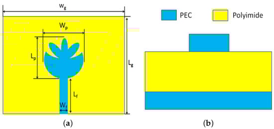
Figure 1.
The proposed novel shape dual-band THz antenna: (a) Front view (b) Side view.
Table 2.
List of parameters used in THz antenna array designing.
Table 2.
List of parameters used in THz antenna array designing.
| Parameters | Values (m) | Parameters | Values (m) |
|---|---|---|---|
| 263.5704698 | 263.6738427 | ||
| 2920 | 1055 | ||
| 45 | 132 | ||
| 1594 | 132 | ||
| 25 | 132 | ||
| 797 | 132 | ||
| 15.3020458 | 132 | ||
| 1558 | 40 | ||
| C | 5 | d | 533 |
| 20 | 10 | ||
| 1 | 1 |
The step by step development of the proposed dual-band THz antenna is designed as mentioned in Figure 2; the group of these shapes is responding in the form of different return losses, as shown in Figure 5.
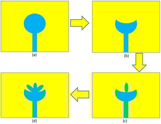
Figure 2.
The development process of dual-band THz antenna: (a) Step 1; (b) Step 2; (c) Step 3; and (d) Step 4.
3. Proposed Array Antenna Design
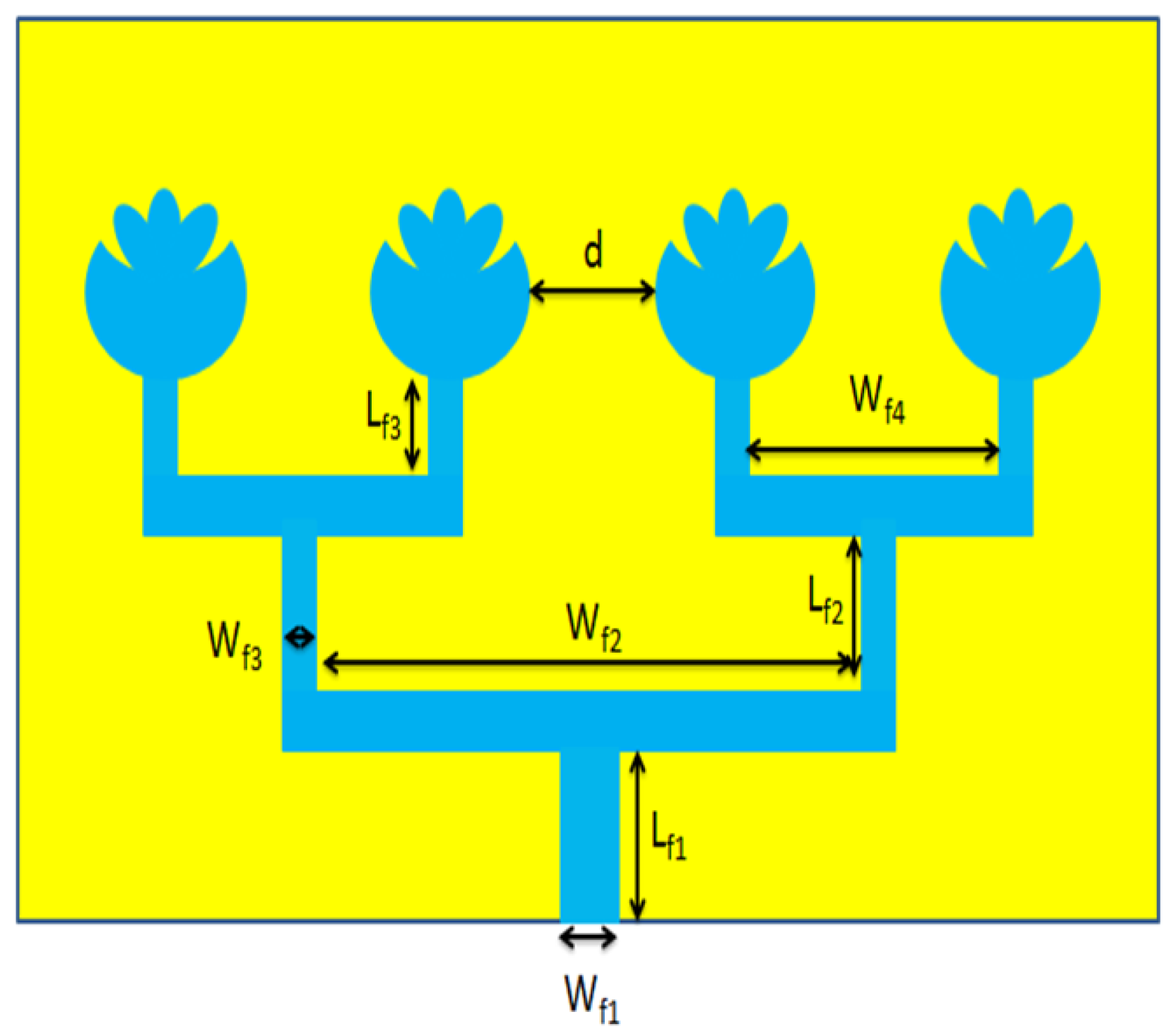
This section focuses on the design aspects of antenna array, where an array is a set of identical radiating element separated by distance d; all are used in matrix order for increasing the gain and directivity of the overall antenna. Therefore, in this section, the proposed novel shape dual-band antenna array design is undertaken, as shown in Figure 3.
As shown in Figure 3, a set of identical elements are placed at a distance of d away from each other. To work with the THz array, it is required to generate and control the amplitude or at least the time delay or phase shift at each radiating antenna that is controlled by separation distance d [24]. From this perspective of dual-band THz antenna, the separation distance d among radiating elements is 533 m, which provides good radiation performance in terms of good return loss, gain, and radiation efficiency, as will be discussed in the next section. All the information about the dimension of the primary boundaries of the four kinds of the THz antenna and arrays is recorded in Table 2.

Figure 3.
Type C dual-band THz antenna array.
Figure 3.
Type C dual-band THz antenna array.
The maximum output gain of the antenna array is controlled by using the array factor (). The array factor of an antenna array depends upon the order of an array and the distance (d) between the radiating elements; besides that, the phase between array elements also takes part in the calculation of the array factor. The array factor () is calculated by using the following equation [24,27,40]:
where, the total directivity of the array is controlled by the array factor () and single-element directivity ().
The total efficiency of the array antenna can be calculated by using the following equation:
where, , , and representing the total efficiency (%), total gain (dB), and directivity (dBi) of the antenna array, respectively.
From now on, the accompanying labeling classification will be utilized to differentiate between the multiple variations of the designed antenna array that are discussed in this paper:
- Type A:
- Novel shape dual-band THz antenna, as displayed in Figure 4a.
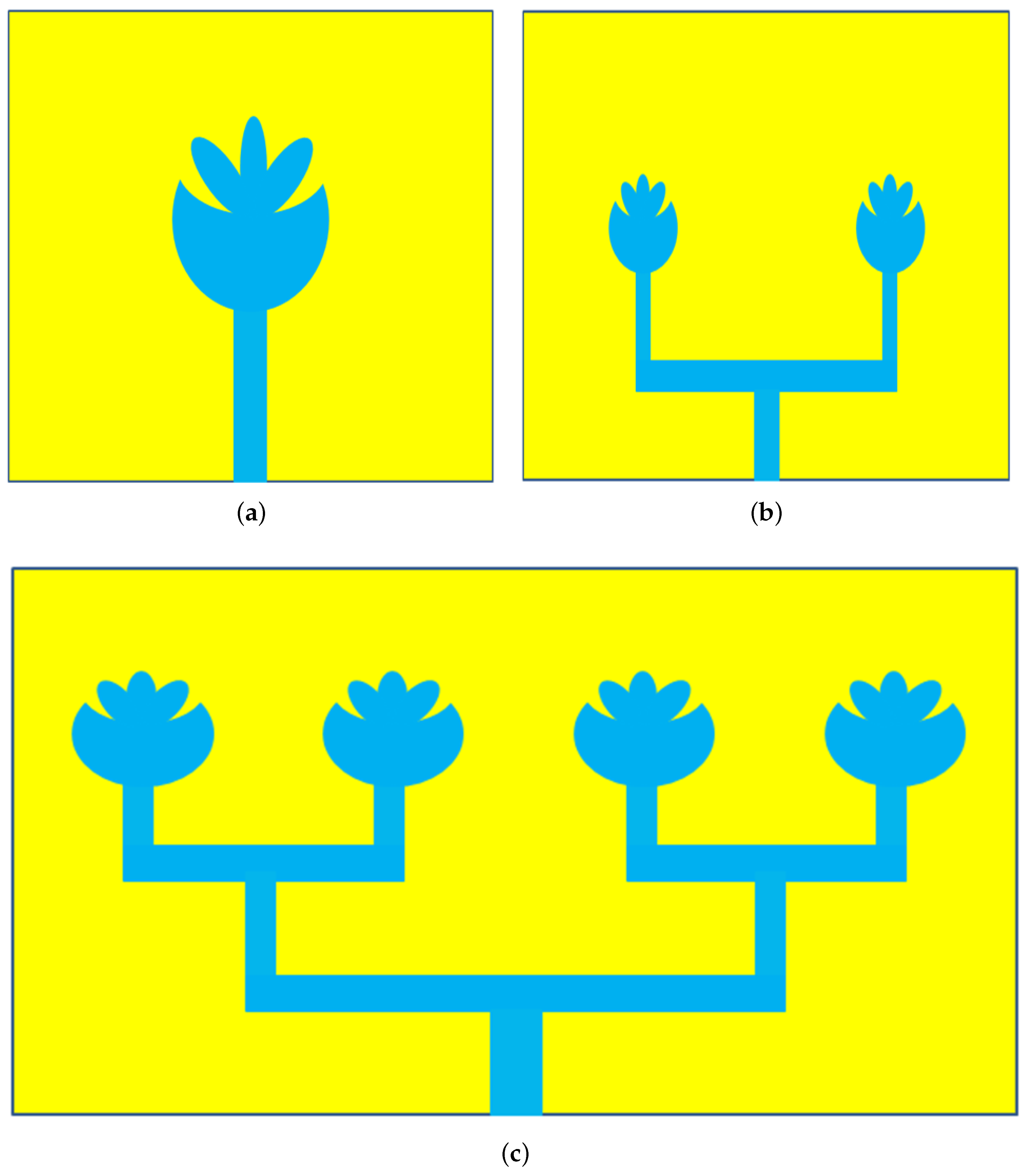
 Figure 4. Design procedure of novel shape dual-band THz antenna array: (a) Type A antenna; (b) Type B antenna array; and (c) Type C antenna array.
 - Type B:
- Dual-band THz antenna array of the order of 2 × 1 as displayed in Figure 4b.
- Type C:
- Dual-band 4 × 1 THz antenna array as displayed in Figure 4c.
The Type A antenna in Figure 4a is designed on a homogeneous polyimide substrate, and this is considered a prospective antenna to assess the performance of different antenna arrays. For increasing the gain of antenna, the order of the antenna array is increased. The Type B antenna array is a 2 × 1 novel shape dual-band THz antenna array based on a homogenous substrate of overall volume of 1324 m × 791 m ×10 m, and each radiating element is separated by 533 µm, as displayed in Figure 4b. Similarly, Type C is displayed in Figure 4c, where four radiating elements are separated by 533 m. Subsequently, it will become evident that the Type C provides the ideal presentation as compared to remaining mentioned types; the radiating elements of the array were designed by utilizing the notable microstrip antenna hypothesis [38]. For feasibility purposes, a parametric sweep is run for getting better results, as shown in Figure 9.
The constructional improvements in the proposed array model are carried out in the following steps, as depicted in Figure 4. These models create a group of reflection coefficients, studied in the next section. The numbers of radiating elements are increased for enhancement purposes in the antenna performance in terms of the high gain, directivity, and low reflection coefficient. In the next step, the Type B THz antenna array is developed; in this development process, a set of two identical novel shape elements are placed in a row by separation distance of 533 m; thus, the Type B THz array is achieved with better gain and directivity at 0.725 and 0.75 THz, respectively. Similarly, in Type C antenna array development process, a set of four identical novel shape elements are placed in a row with separation distance of 533 m. Thus, a high-gainand directive 4 × 1 THz array antenna is designed.
4. Simulation
For multiple applications, such as radio astronomy, spectroscopy, free space satellite communication, and space research, the proposed dual-band 4 × 1 novel shape THz antenna array is suggested, which operates at 0.714 and 0.7412 THz, respectively. The operational features of the presented antenna are inspected in the frequency range 0.675 to 0.775 THz by utilizing the finite integration technique (FIT) [41]. The details about design and simulation are listed in Table 3. The simulation results of the antenna models are discussed in terms of return loss, gain, directivity, impedance, band width (BW), and radiation efficiency in the mentioned frequency band.
Table 3.
Investigation of presented antenna models by simulation parameters.
In first section, the return losses of all the steps are discussed, as shown in Figure 5, which are useful for the proposed novel shape antenna design analysis. In the second section, the return losses and voltage standing wave ratio (VSWR) of the Type A, Type B, and Type C antenna arrays are discussed in Figure 6, Figure 7, Figure 8, Figure 9 and Figure 10. The third section deals with the study of Type A, Type B, and Type C antenna array 2D radiation polar plots, and it is discussed in Figure 13. Similarly, the fourth section presents the far-field radiation patterns of all types of antenna arrays, such as Type A, Type B, and Type C as shown in Figure 14. The final fifth section presents the gain (dB) and radiation efficiency (%) verses frequency (THz) graphs of all types antenna arrays, including Type A, Type B, and Type C as shown Figure 15.
As mentioned earlier, Figure 5 analyzes the return losses verses frequency graphs for single-element antennas, such as the Step 1, 2, 3, and 4 antennas, which resonate at 0.714, 0.698, and 0.702 THz, respectively. Step 4 is dual-band antenna resonating at 0.714 and 0.7412 THz with −10 dB bandwidths of 4.71 and 3.13 GHz, respectively.
It is observed in Figure 5 that the Step 1 antenna resonates at 0.6985 THz, providing a −10 dB bandwidth of 8.67 GHz. The resonance frequency of Step 2 antenna is slightly shifted toward right side, and it operates at 0.7025 THz and provides a −10 dB bandwidth of 15.44 GHz. Similarly, the resonance frequency of the Step 3 antenna is further slightly shifted toward the right side, and it operates at 0.711 THz and provides a −10 dB bandwidth of 11.73 GHz. Moreover, the Step 4 antenna is a dual-band antenna; it operates at 0.7085 and 0.75225 THz with −10 dB bandwidths of 9.08 and 6.34 GHz, respectively. Figure 7 provides comparable information about the impedance matching of the Step 4 antenna and the equivalent circuit model, while Figure 6 presents the equivalent circuit model of the dual-band THz antenna and feed line as mentioned in Step 4. The equivalent circuit of the proposed dual-band antenna comprises a radiating patch and a feed line; the radiating patch is represented by one resistor (R), two inductors (L), and one capacitor (C). All of them are connected in parallel. These parameters are represented by , and , respectively, as shown in Figure 6. While the equivalent circuit model of feed line is made of two inductors (L) and two capacitors (C), each of them are connected in series and parallel with each other; these parameters are represented by , and , respectively, as shown in Figure 6.
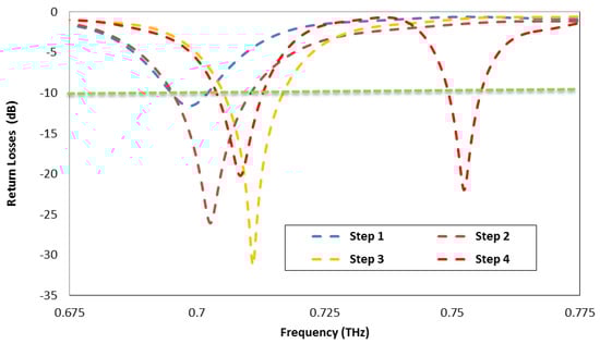
Figure 5.
Evaluation of Type A/Step 4 antenna with the help of return loss vs. frequency graph.
Figure 5.
Evaluation of Type A/Step 4 antenna with the help of return loss vs. frequency graph.
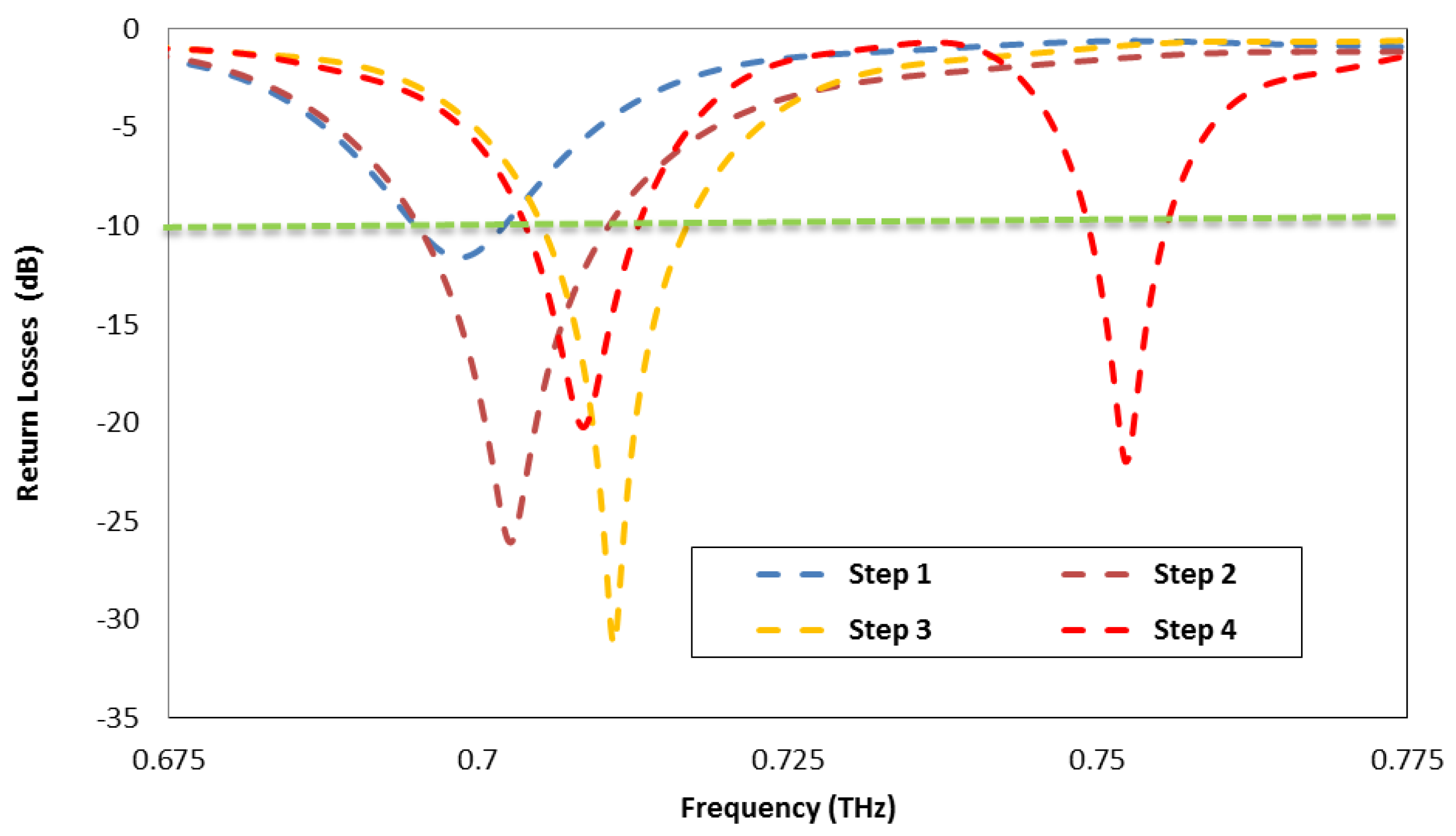
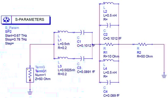
Figure 6.
Equivalent circuit model of dual-band THz antenna.
Figure 6.
Equivalent circuit model of dual-band THz antenna.
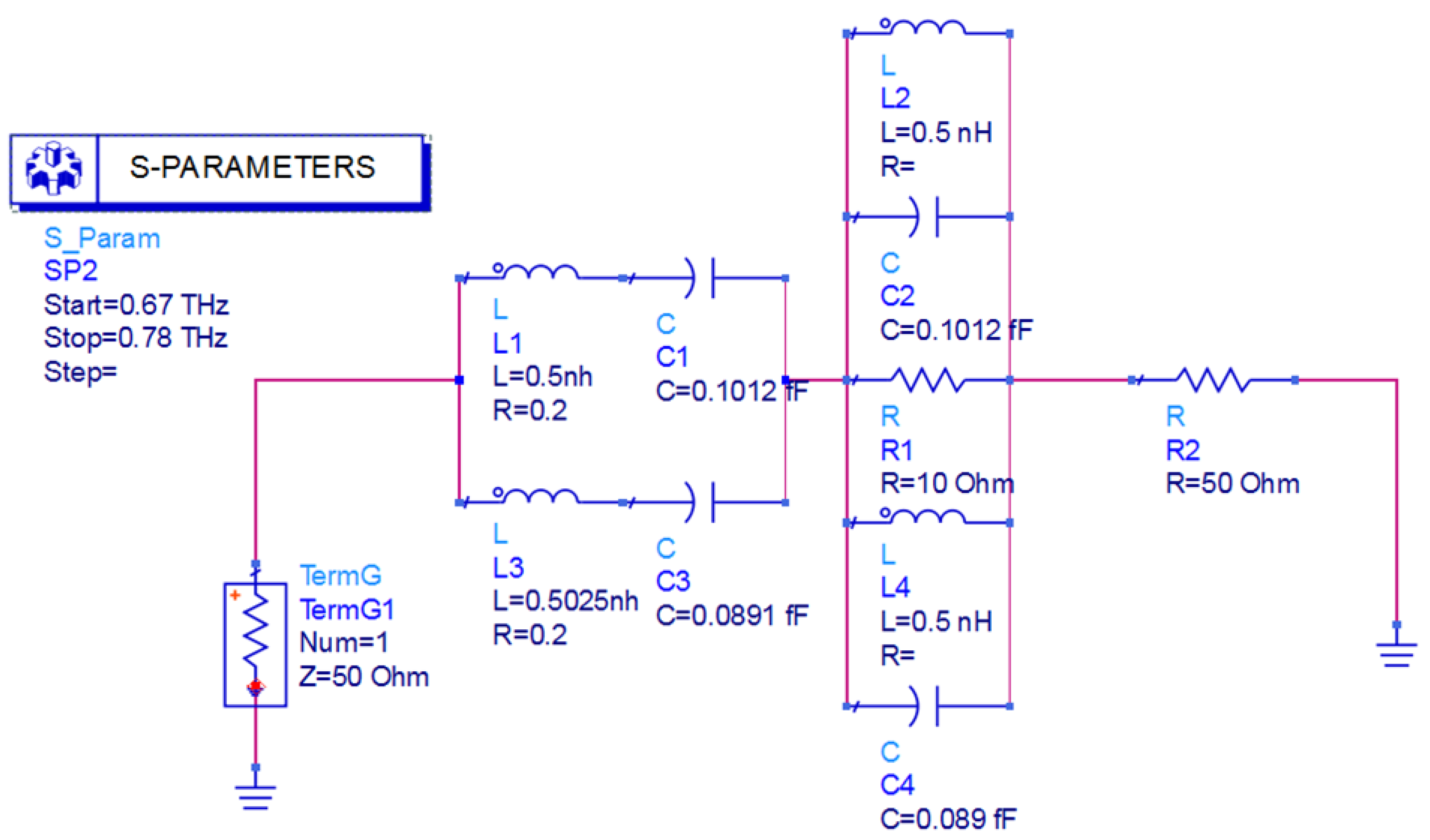
The resonance frequencies and of the proposed RLC circuit is calculated by using a resonance circuit formula [42].
The calculated and equivalent circuit model (ECM) first and second resonance frequencies and are listed in Table 4 and Table 5, respectively. Similarly, the bandwidths and of the proposed equivalent circuit model (ECM) are calculated by using the following equations:
The calculated and equivalent circuit model (ECM) bandwidths and of the first and second resonance frequency bands are listed in Table 4 and Table 5.
Table 4.
List of parameters for first resonance frequency
Table 4.
List of parameters for first resonance frequency
| Parameters | (nH) | (fF) | (nH) | (fF) | Calculated (THz) | ECM (THz) | Calculated (GHz) | ECM (GHz) |
|---|---|---|---|---|---|---|---|---|
| Values | 0.5 | 0.1012 | 0.5 | 0.1012 | 0.70831 | 0.7085 | 10 | 10 |
Table 5.
List of parameters for second resonance frequency
Table 5.
List of parameters for second resonance frequency
| Parameters | (nH) | (fF) | (nH) | (fF) | Calculated (THz) | ECM (THz) | Calculated (GHz) | ECM (GHz) |
|---|---|---|---|---|---|---|---|---|
| Values | 0.5025 | 0.0891 | 0.5 | 0.089 | 0.753 | 0.7525 | 10 | 10 |
The reflection coefficient of the proposed dual-band novel shape THz antenna is tuned according to the resonance frequencies by changing the magnitudes of the capacitors and inductors. The mutual correlation between the reflection coefficients of the proposed dual-band Step 4 THz antenna and the equivalent RLC circuit model is compared in Figure 7, which presents strong agreement between the two reflection coefficients. The calculated and equivalent circuit model results shown in Table 4 and Table 5 suggest that the first resonance frequency is associated with the values of and , while the second resonance frequency is tuned with the values of , and , respectively. The first resonance frequencies, i.e., the calculated calculated version and equivalent circuit model ECM version, are 0.708314 and 0.7085 THz, respectively. Similarly, the second resonance frequencies, i.e., the calculated version and equivalent circuit model ECM version, are 0.753 and 0.7525 THz, respectively.
The calculated and equivalent circuit model results show that the first bandwidth is associated with the values of and , while the second bandwidth is tuned with the values of , and , respectively. The calculated and equivalent circuit model bandwidths are 10 and 10 GHz for the first resonance frequency at 0.708314 and 0.7085 THz, respectively. Similarly, the calculated and equivalent circuit model bandwidths are 10 and 10 GHz for the second resonance frequency at 0.753 and 0.7525 THz, respectively. Table 2 shows the parameters of Type C antenna array. It is clear from Figure 8 that the Type A antenna array operates at 0.7085 and 0.75225 THz, with −10 dB band widths of 9.12 and 6.4 GHz, respectively. The resonant frequencies and of the Type B antenna is somewhat moved to 0.698 and 0.758 THz, and providing −10 dB bandwidth of 8.37 and, 6.83 GHz, respectively. The Type C antenna provides resonance at frequencies of 0.714 and 0.7412 THz with a −10 dB band width of 4.71 and 3.13 GHz, respectively. From Figure 8, it can be seen that the operating bandwidth of the Type C antenna for the 0.714 THz frequency fluctuates in the range of 0.711–0.716 THz, while for the 0.741 THz frequency, it varies from 0.739–0.742 THz.
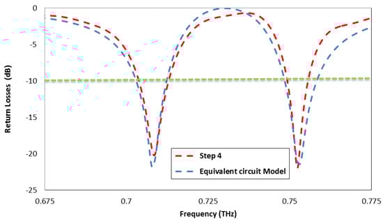
Figure 7.
Return losses of dual-band Step 4 THz antenna and equivalent circuit model.
Figure 7.
Return losses of dual-band Step 4 THz antenna and equivalent circuit model.
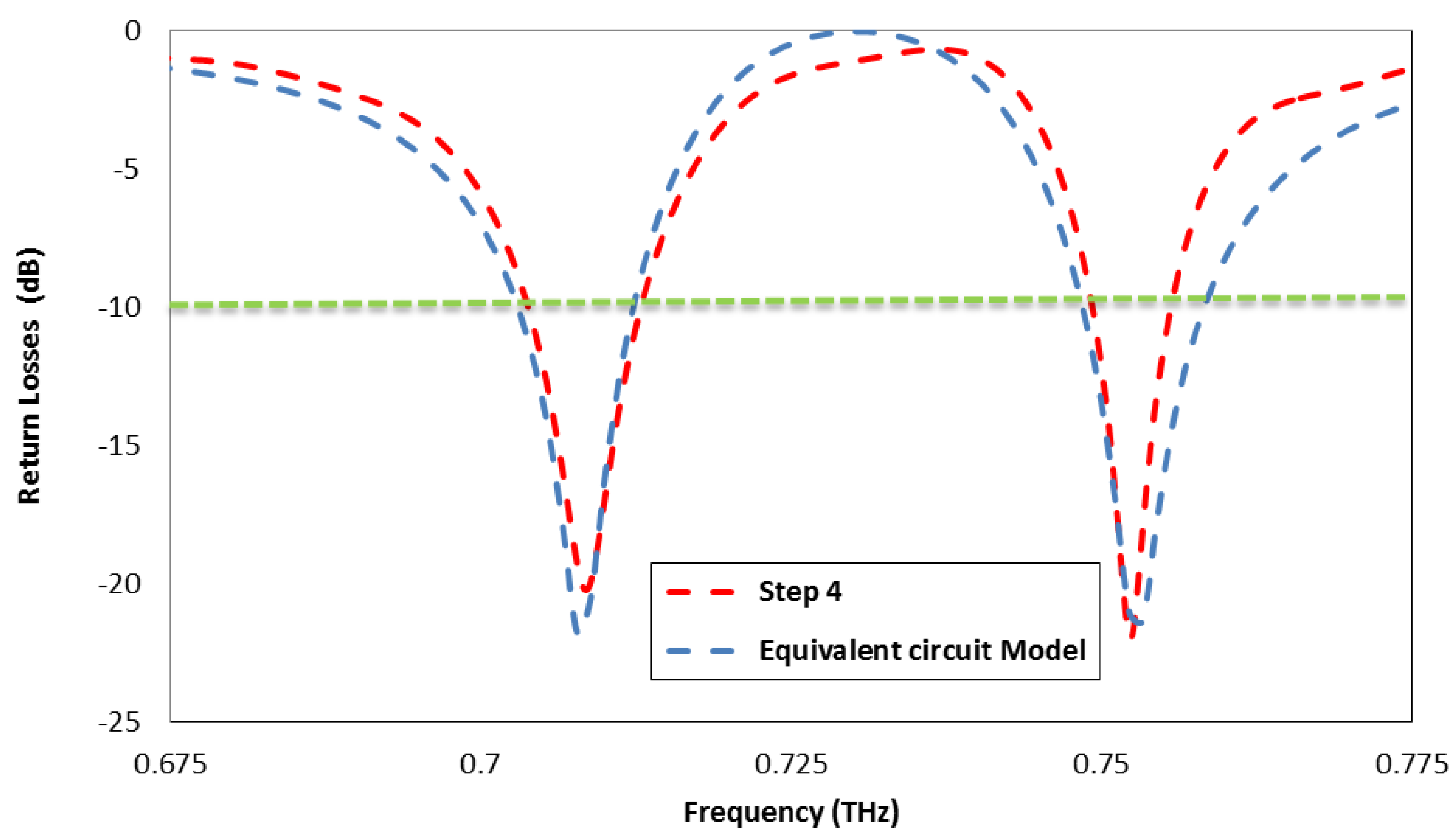
Figure 8.
Comparison of return loss vs. frequency.
Figure 8.
Comparison of return loss vs. frequency.
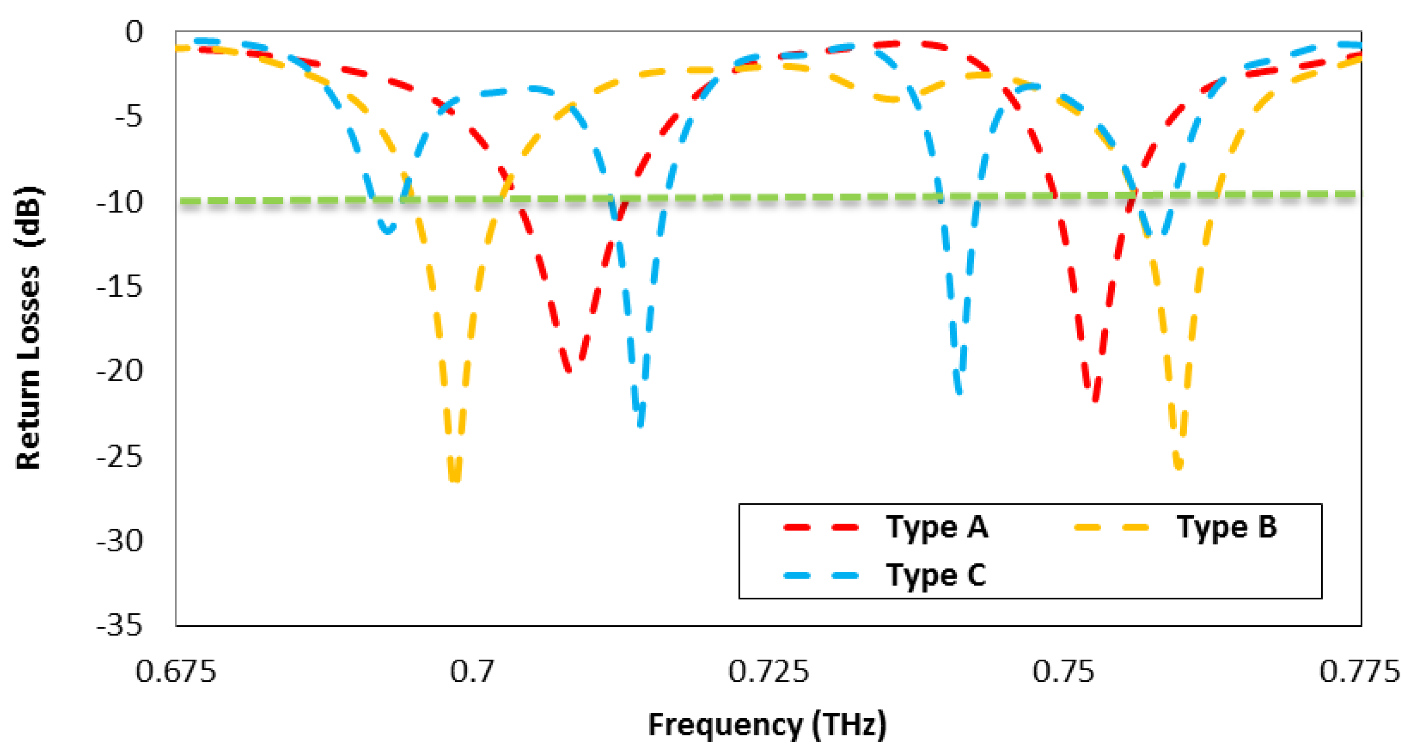
In Figure 8, the small variations in the operating bands are compromised to obtain good performance results at a separation distance d of 533 m. However, a dual-band antenna array is still operating in the allocated bands, which are reserved for the mentioned applications.
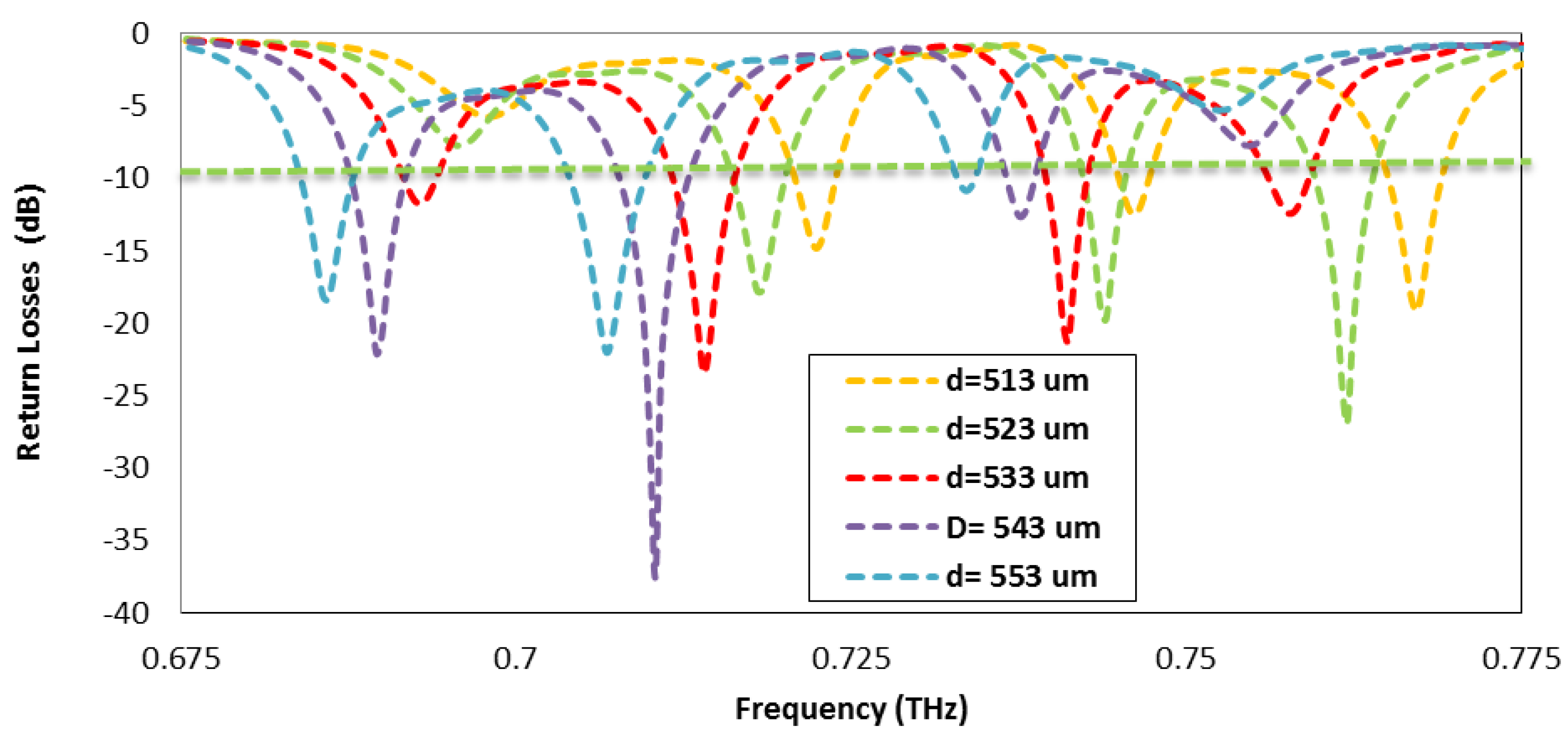
In the case of every antenna array, the order of array and separation distance d among the radiating elements are very important parameters as they play a very significant role with respect to the operating bands because they define the behavior of the antenna array in terms of return loss. For comparison proposes, the reflection coefficients of Type A, Type B, and Type C antenna arrays are plotted in Figure 8. The parametric analysis of the Type C antenna array on the basis of separation distance d among the radiating elements is taken into account from 513–553 m, as plotted in Figure 9, where the separation distance of 533 m provides a better return loss of −20 dB at 0.714 and 0.7412 THz, respectively.

Figure 9.
Parametric analysis of Type C antenna array.
Figure 9.
Parametric analysis of Type C antenna array.
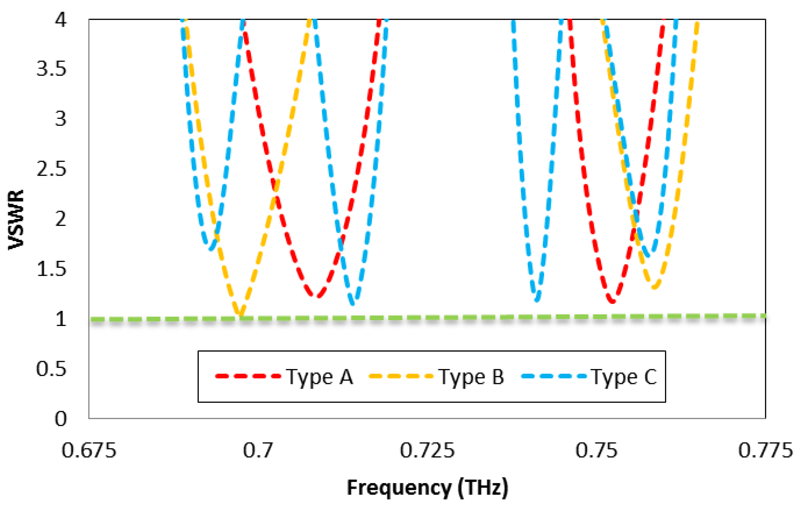
In Figure 10, the voltage standing wave ratios (VSWRs) of the Type A, Type B, and Type C antennas are analyzed and compared. The Type A antenna provides VSWRs of 1.21 and 1.17 while operating at 0.708 and 0.75225 THz, respectively. Similarly, the Type B antenna provides VSWRs of 1.01 and 1.27 while operating at 0.689 and 0.758 THz, respectively. Similarly, the Type C antenna provides VSWRs of 1.14 and 1.18 while operating at of 0.714 and 0.7412 THz, respectively. These results of the VSWR show strong agreement with the ideal value of 1, which is considered a reasonably matched antenna with the feed line.
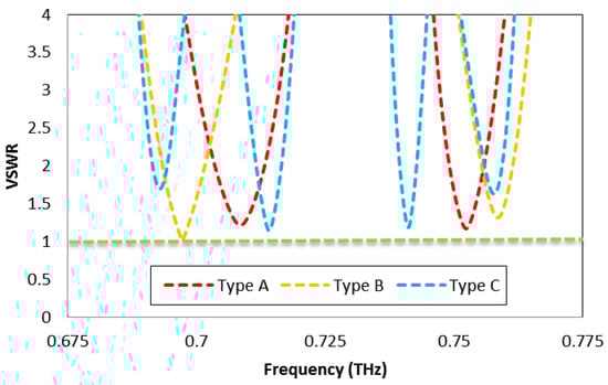
Figure 10.
Comparison of all types of array antennas on the bases of VSWR.
Figure 10.
Comparison of all types of array antennas on the bases of VSWR.
In Figure 11, the insertion losses of the Type A, Type B, and Type C antenna arrays are depicted; it is clear that the Type C antenna has low insertion losses of 0.021 and 0.05 dB compared to the Type A and B antennas.
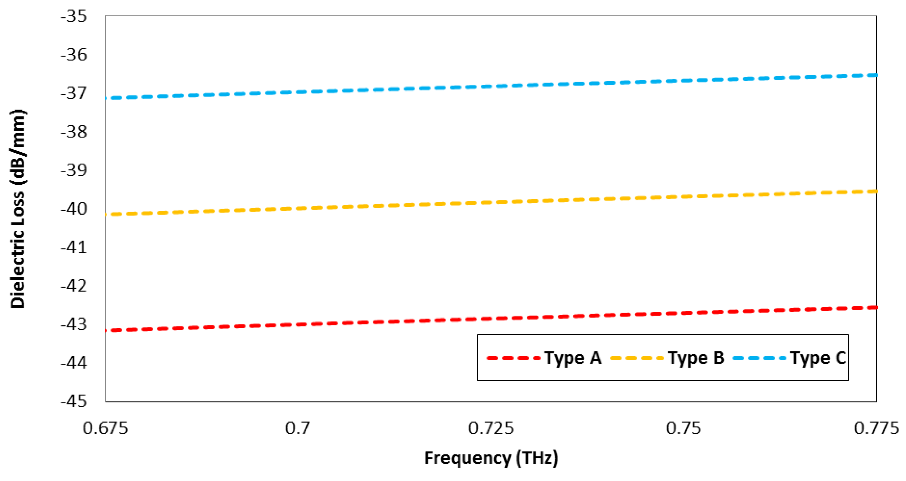
In Figure 12, the dielectric losses per millimeter are depicted for the Type A, Type B, and Type C antennas. The applied voltage for all the antennas is 5 volts, while the value of capacitance C varies with respect to the effective area of the antennas. Therefore, the Type A, Type B, and Type C antennas have different dielectric losses per millimeter, as mentioned in Figure 12.
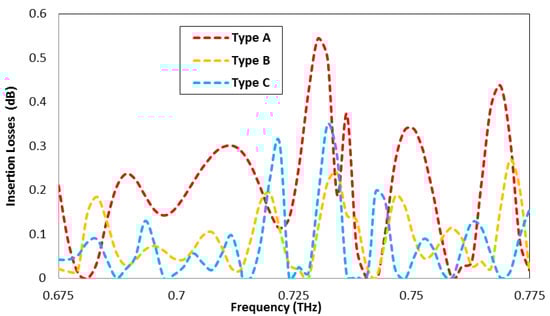
Figure 11.
The insertion losses of Type A, Type B, and Type C antennas.
Figure 11.
The insertion losses of Type A, Type B, and Type C antennas.
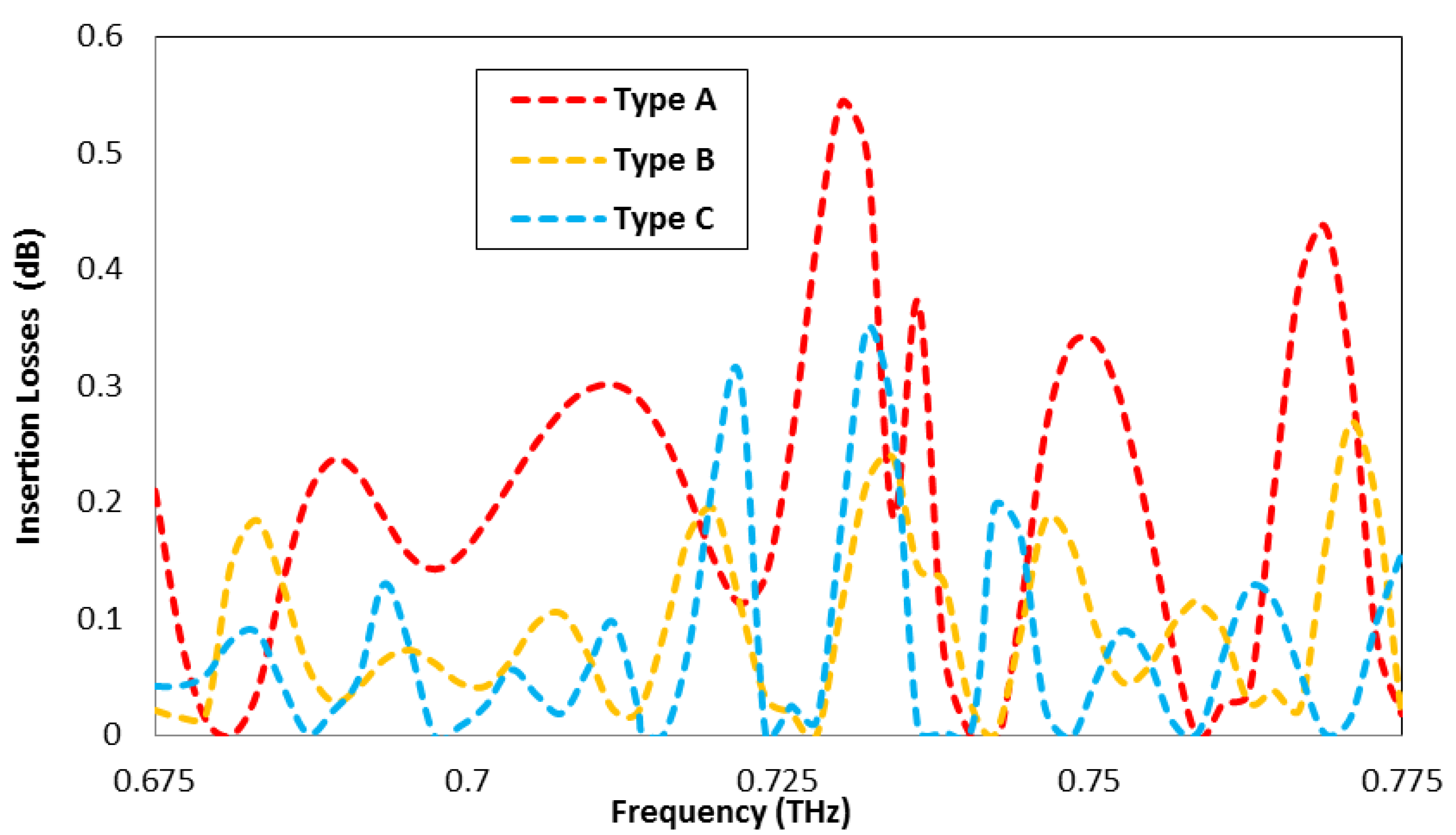
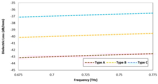
Figure 12.
The dielectric loss per millimeter of Type A, Type B, and Type C antennas.
Figure 12.
The dielectric loss per millimeter of Type A, Type B, and Type C antennas.
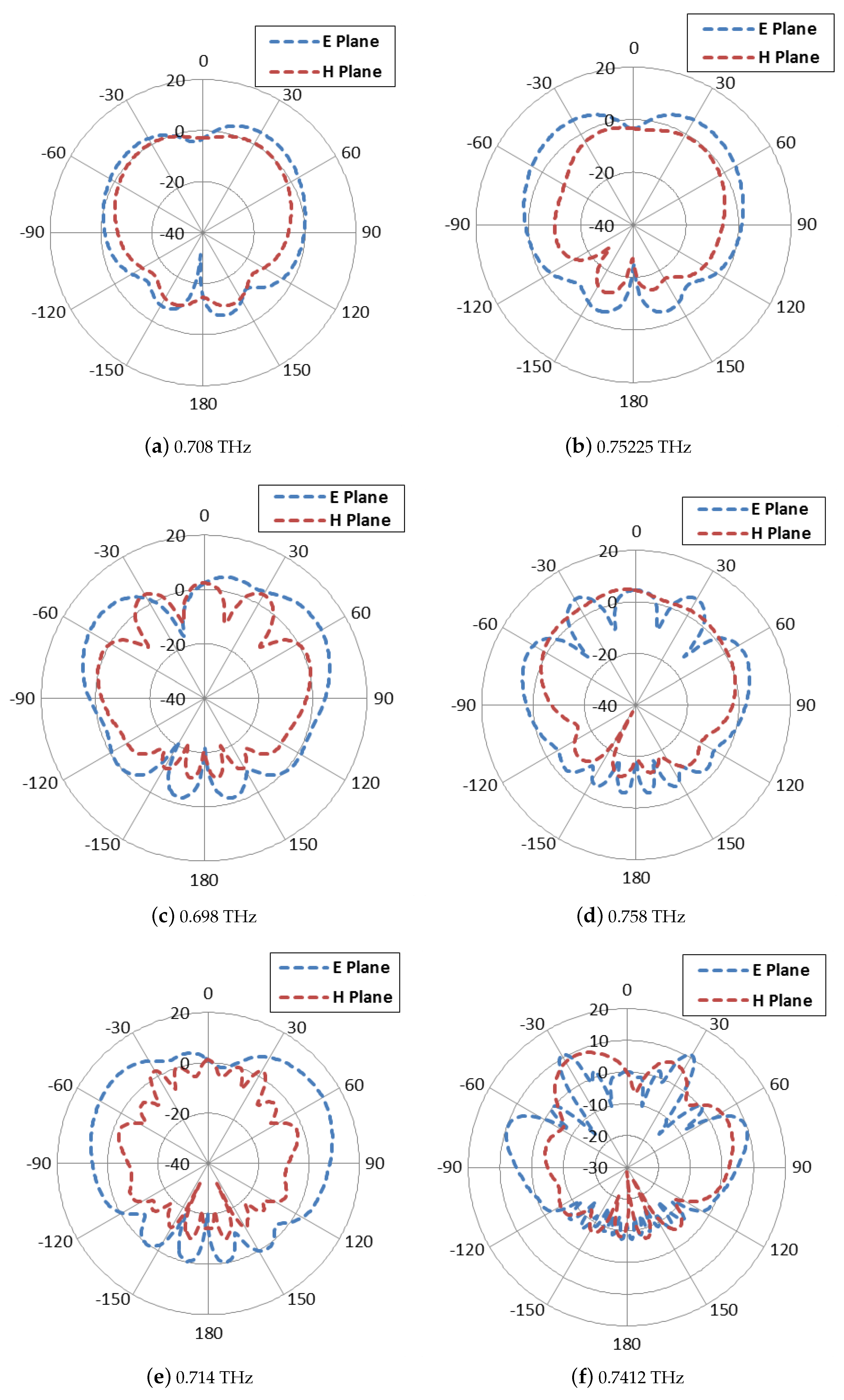
The 2D polar plots and 3D radiation patterns of Type A antenna, Type B antenna, and Type C antenna are shown in Figure 13 and Figure 14, respectively. The simulation results show that the dual-band type A antenna directs the THz signals at and with the half power beam widths (HPBW) of and , the side lobe of −2.2 and −1.8 dB, while operating at frequencies of 0.708 and 0.75225 THz with main lobe magnitudes of 5.51 and 6.25 dB and a radiation efficiency of 91.66 and 90.35%, respectively. Similarly, the Type B antenna array directs the THz signals at and with the half-power beam widths (HPBW) of and , with side lobes of −4.5 and −2.7 dB while operating at frequencies of 0.689 and 0.758 THz with main lobe magnitudes of 9.95 and 7.75 dB and radiation efficiencies of 96.09 and 95.45%, respectively. Additionally, the Type C antenna array directs the THz signals at and with the half-power beam width (HPBW) of and , with side lobes of −2.2 and −2.7 dB while operating at frequencies of 0.714 and 0.7412 THz with main lobe magnitudes of 12.5 and 11.23 dB and radiation efficiencies of 99.76 and 96.6%, respectively. From these values, it is concluded that as the number of transmitting elements increases in the array, the dual-band THz antenna array becomes more directive.The THz antenna is reasonably matched with feed lines, which is why the side lobes are negligible and the array antennas are more than 90 % efficient.
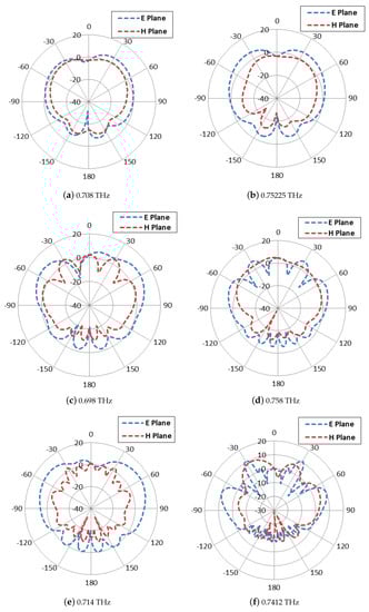
Figure 13.
A comparison of the Type A, Type B, and Type C antenna arrays on the bases of polar plots: (a) Type A at 0.708 THz, (b) Type A at 0.75225 THz, (c) Type B at 0.698 THz, (d) Type B at 0.758 THz, (e) Type C at 0.714 THz, and (f) Type C at 0.7412 THz.
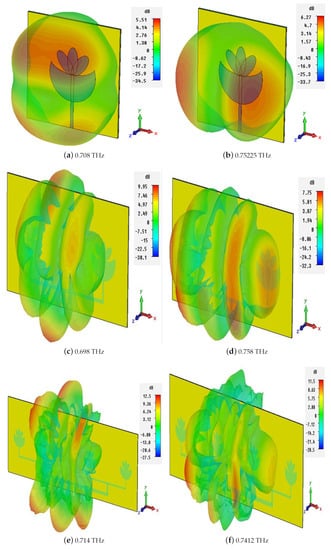
Figure 14.
Far field radiation pattern: (a) Type A at 0.708 THz, (b) Type A at 0.75225 THz, (c) Type B at 0.698 THz, (d) Type B at 0.758 THz, (e) Type C at 0.714 THz, and (f) Type C at 0.7412 THz.
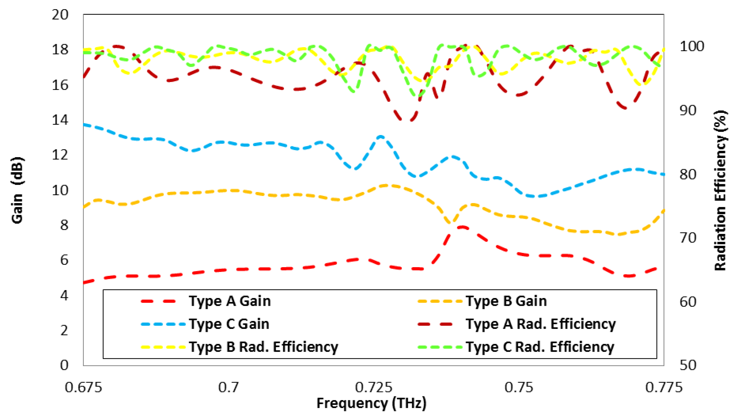
The main purpose of designing of an antenna array from a single-element antenna is achieving a better results in antenna performance in terms of gain and directivity. Figure 15 suggests that as the numbers of radiating elements are increased in an antenna array, it results in a higher gain. From Figure 15, it can be seen that the gain of the Type C antenna for the 0.714 THz frequency band fluctuates in the range of 11.23–12.72 dB, while for the 0.741 THz frequency band, it varies from 9.65 dB to 11.64 dB. In addition, the efficiency of the Type C antenna for the 0.714 THz frequency band fluctuates in the range of 98.5–98.7% with a peak value of 99.7% at resonance frequency, while for the 0.741 THz frequency band, it varies from 98.9% to 95.57% with 96.6% at the resonance frequency; these efficiency ranges are greater than 95% for both bands, as shown in Figure 15.
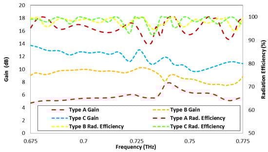
Figure 15.
Comparison of gains and radiation efficiencies of Type A, Type B, and Type C antenna arrays.
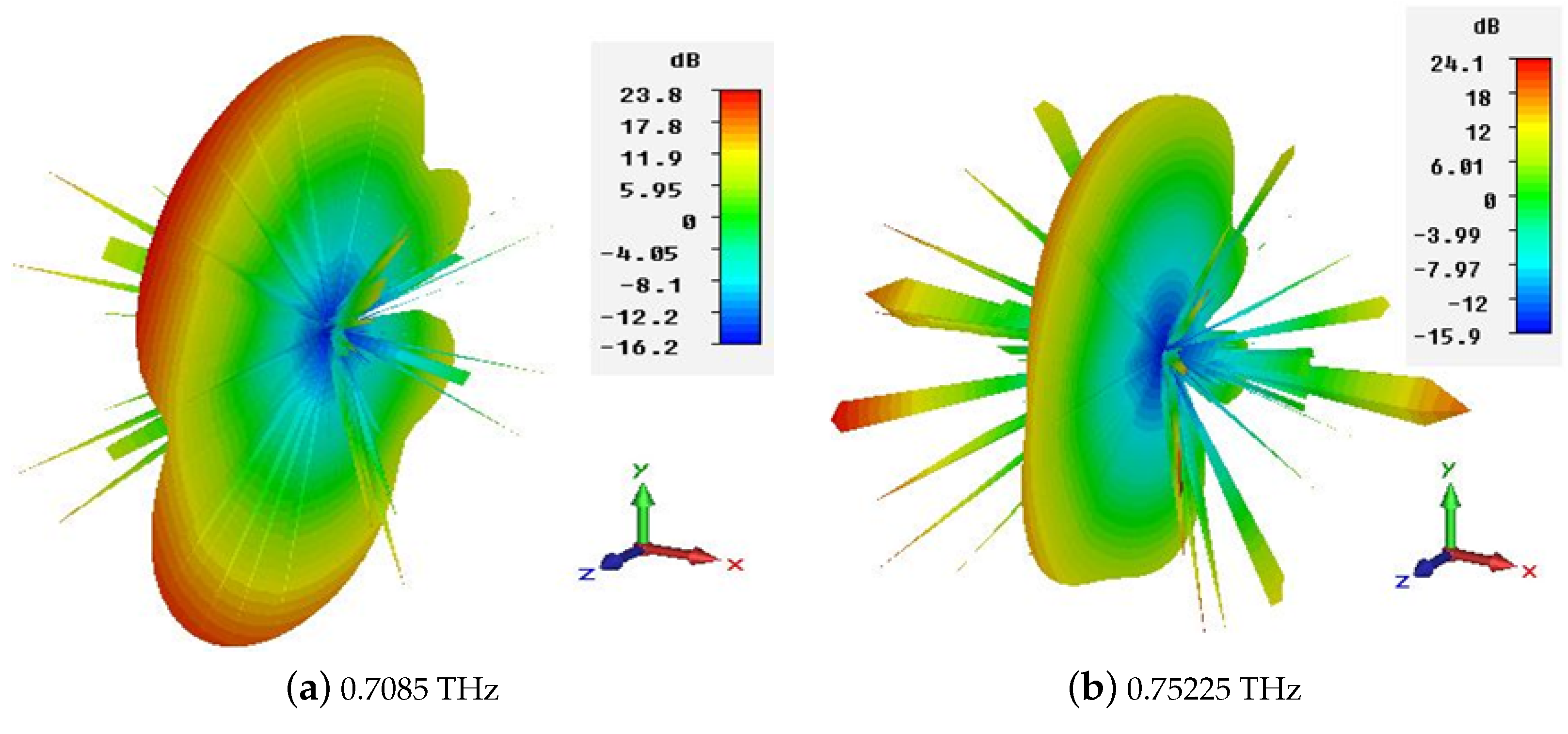
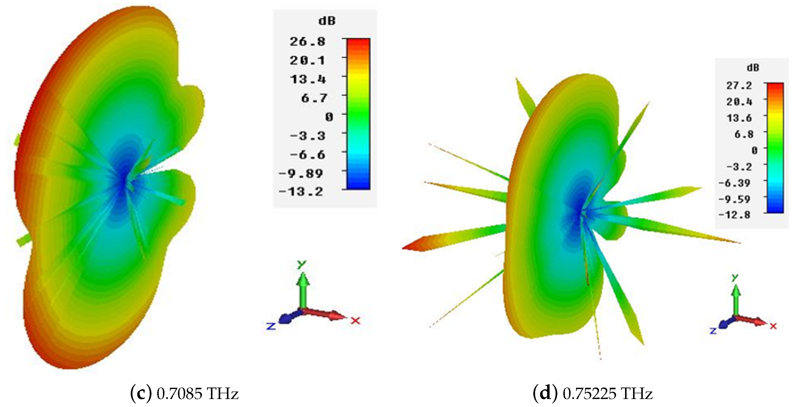
As mentioned in the introduction section, the space communication demands a high directive antenna of at least 24 dBi. For the purpose of achieving the recommended gain and directivity, the CST microwave studio built-in array tool kit is used to calculate the array 3D pattern and the required gain and directivity from a single element with the help of an array factor (). For simplification purposes, the following labeling is adopted: Type D: dual-band 64 × 1 THz antenna array; Type E: dual-band 128 × 1 THz antenna array. The polar plot and 3D radiation pattern of the 64 × 1 and 128 × 1 element arrays are depicted in Figure 16 and Figure 17, respectively, which show that the beam width becomes narrower and a peak gain of 23.8 and 24.1 dB, and 26.8 and 27.2 dB, can be achieved, respectively.
For comparison purpose, Table 6 depicts a summary of type A, B, C, D and E THz antenna array results in term of gain (dB).
Table 6.
Comparison of gains of various antenna arrays.
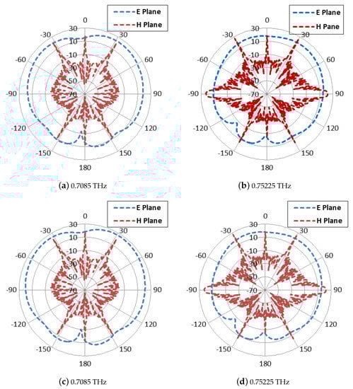
Figure 16.
Comparison of polar plots for dual-band Type D and Type E THz antenna array. (a) Type D antenna array at 0.7085 THz (b), Type D antenna array at 0.75225 THz, (c) Type E antenna array at 0.7085 THz, and (d) Type E antenna array at 0.75225 THz.
Figure 16.
Comparison of polar plots for dual-band Type D and Type E THz antenna array. (a) Type D antenna array at 0.7085 THz (b), Type D antenna array at 0.75225 THz, (c) Type E antenna array at 0.7085 THz, and (d) Type E antenna array at 0.75225 THz.
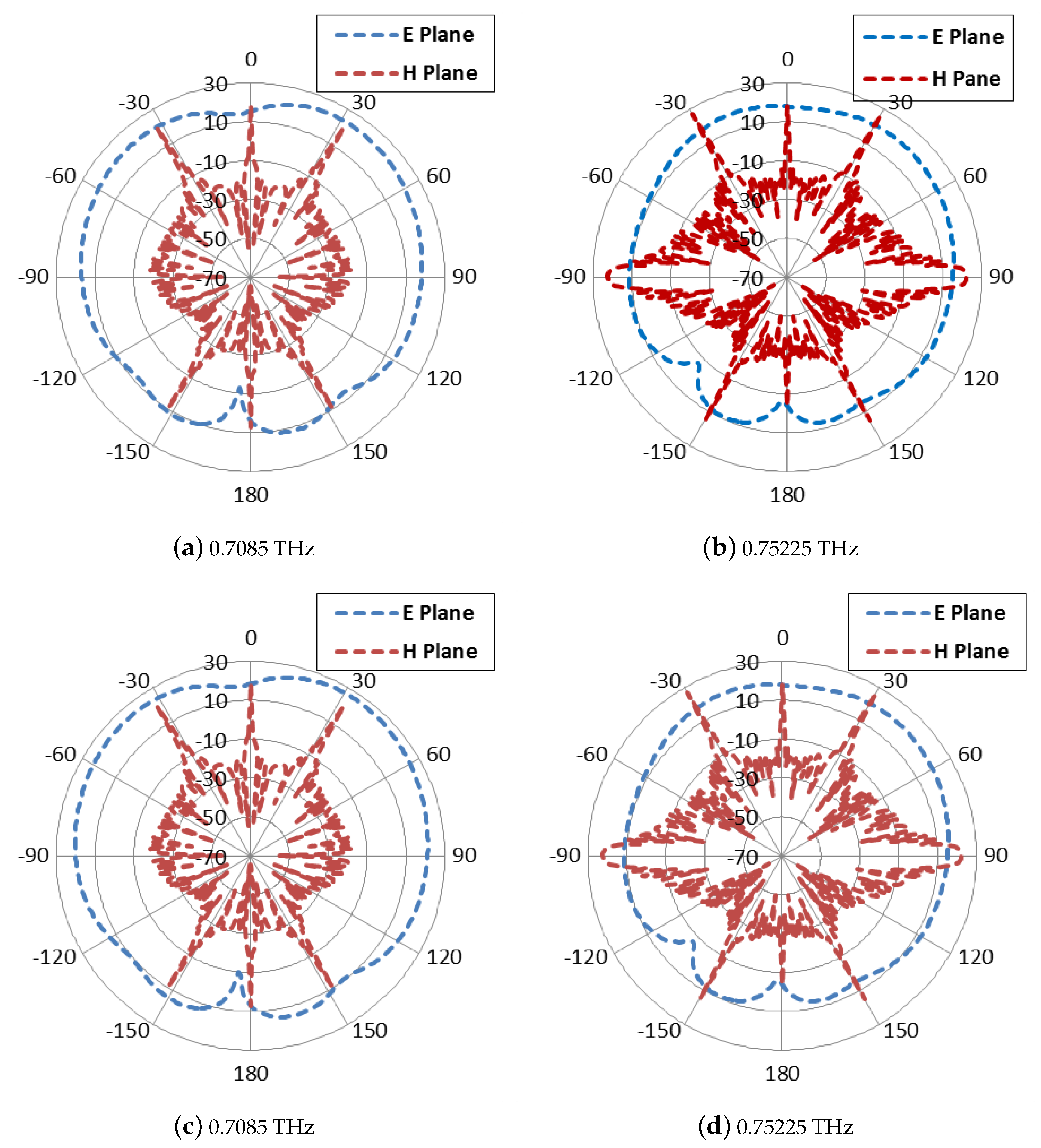
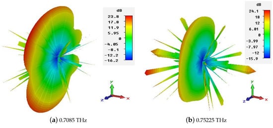
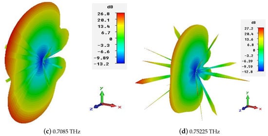
Figure 17.
Comparison of 3D radiation pattern for dual-band Type D and E THz antenna array. (a) Type D antenna array at 0.7085 THz, (b) Type D antenna array at 0.75225 THz, (c) Type E antenna array at 0.7085 THz, and (d) Type E antenna array at 0.75225 THz.
Figure 17.
Comparison of 3D radiation pattern for dual-band Type D and E THz antenna array. (a) Type D antenna array at 0.7085 THz, (b) Type D antenna array at 0.75225 THz, (c) Type E antenna array at 0.7085 THz, and (d) Type E antenna array at 0.75225 THz.
5. Conclusions
In the present work, the dual-band THz antenna array is analyzed and compared with respect to design characteristic performance. The radiation properties of the proposed novel array antenna have been analyzed with multiple radiating elements. Furthermore, the effects of the separation distance among the radiating elements have also been analyzed for Type C antenna. The directivity and gain of the proposed novel THz array antenna are 12.5 and 11.23 dB, and 12.532 and 11.625 dBi, at 0.714 and 0.7412 THz with 99.76 and 96.6% radiation efficiency, respectively. The minimal return loss of the simulated type C antenna is examined in the parameter sweep, less than −37 dB at a corresponding separation distance d of 533 m at a resonant frequency of 0.7123 THz. The effects of the variation in the number of radiating elements on the return loss and on the gain have also been observed, and it has also been concluded that with the increase in the number of radiation elements, the bandwidth of the antenna decreases significantly. Hence, the proposed array antenna is a potential candidate to be utilized for earth exploration satellite and space research.
Author Contributions
Conceptualization, W.S. and S.U.; data curation, W.S., S.U. and N.A.A.; funding acquisition, D.-y.C. and A.A.; methodology, W.S. and S.U.; project administration, W.S., S.U. and N.A.A.; resources, D.-y.C., S.U. and N.A.A.; software, W.S. and S.U.; supervision, S.U. and D.-y.C.; validation, W.S., N.A.A. and A.A.; writing—original draft, W.S.; and writing—review and editing, N.A.A. and W.S. All authors have read and agreed to the published version of the manuscript.
Funding
This research was supported by the Basic Science Research Program through the National Research Foundation of Korea (NRF) funded by the Ministry of Education (2022R1I1A3064544).
Institutional Review Board Statement
Not applicable.
Informed Consent Statement
Not applicable.
Data Availability Statement
Not applicable.
Conflicts of Interest
The authors declare no conflict of interest.
References
- Zhou, H.; Jong, M.; Lo, G. Evolution of Satellite Communication Antennas on Mobile Ground Terminals. Int. J. Antennas Propag. 2015, 2015, e436250. [Google Scholar] [CrossRef]
- Ushaben, K.; Sanyog, R.; Kanad, R. Inverted K-shaped antenna with partial ground for THz applications. Optik 2020, 219, 165092. [Google Scholar] [CrossRef]
- Technical and Operational Characteristics and Applications of the Point-to-Point Fixed Service Applications Operating in the Frequency Band 275–450 GHz; Technical Report, Report ITU-R F.2416-0; ITU: Geneva, Switzerland, 2017.
- Protection of the Radio Astronomy Services from Transmitters Operating in Adjacent Bands; Technical Report ITU-R RA.517-3; ITU: Geneva, Switzerland, 2003.
- Technology Trends of Active Services in the Frequency Range 275–3000 ghz; Technical Report ITU-R SM.2352-0; ITU: Geneva, Switzerland, 2015.
- Ahmad, I.; Ullah, S.; Ullah, S.; Habib, U.; Ahmad, S.; Ghaffar, A.; Alibakhshikenari, M.; Khan, S.; Limiti, E. Design and Analysis of a Photonic Crystal Based Planar Antenna for THz Applications. Electronics 2021, 10, 1941. [Google Scholar] [CrossRef]
- Hara, F.O.; Grischkowsky, D.R. Comment on the veracity of the ITU-R recommendation for atmospheric attenuation at terahertz frequencies. IEEE Trans. Terahertz Sci. Technol. 2018, 8, 372–375. [Google Scholar] [CrossRef]
- Steinkerchner, L.; Welch, B.; Welch, B. Augmenting the SCaN Link Budget Tool with Validated Atmospheric Propagation, 2017. Available online: https://ntrs.nasa.gov/citations/20170010174 (accessed on 21 June 2022).
- Siles, G.A.; Riera, J.M.; Garcia-del-Pino, P. Atmospheric Attenuation in Wireless Communication Systems at Millimeter and THz Frequencies. IEEE Antennas Propag. Mag. 2015, 57, 48–61. [Google Scholar] [CrossRef]
- Kokkoniemi, J.; Lehtomäki, J.; Juntti, M. Simplified molecular absorption loss model for 275–400 gigahertz frequency band. In Proceedings of the 12th European Conference on Antennas and Propagation (EuCAP 2018), London, UK, 9–13 April 2018; Available online: https://ieeexplore.ieee.org/abstract/document/8568124/ (accessed on 21 June 2022).
- Sector, I.R. Recommendation, Attenuation by Atmospheric Gases; Technical Report; International Telecommunications Union: Geneva, Switzerland, 2013. [Google Scholar]
- Hocini, A.; Temmar, M.N.; Khedrouche, D.; Zamani, M. Novel approach for the design and analysis of a terahertz microstrip patch antenna based on photonic crystals. Photonics Nanostruct.—Fundam. Appl. 2019, 36, 100723. [Google Scholar] [CrossRef]
- Welch, W.J. 1.2. Types of Astronomical Antennas. Methods Exp. Phys. 1976, 12, 7–28. [Google Scholar] [CrossRef]
- Song, P. Present and Future of Terahertz Communications. IEEE Trans. Terahertz Sci. Technol. 2011, 1, 256. [Google Scholar] [CrossRef]
- Hwu, S.U.; de Silva, K.B.; Jih, C.T. Terahertz (THz) wireless systems for space applications. In Proceedings of the 2013 IEEE Sensors Applications Symposium Proceedings, Galveston, TX, USA, 19–21 February 2013. [Google Scholar]
- Woolard, D.L.; Jensen, J.O.; Hwu, R.J. Terahertz Science and Technology for Military and Security Applications; World Scientific: Singapore, 2017; Volume 46. [Google Scholar]
- Petrov, V.; Pyattaev, A.; Moltchanov, D.; Koucheryavy, Y. Terahertz band communications: Applications, research challenges, and standardization activities. In Proceedings of the 2016 8th International Congress on Ultra Modern Telecommunications and Control Systems and Workshops (ICUMT), Lisbon, Portugal, 18–20 October 2016. [Google Scholar]
- Tekbıyık, K.; Ekti, A.R.; Kurt, G.K.; Görçin, A. Terahertz band communication systems: Challenges, novelties and standardization efforts. Phys. Commun. 2019, 35, 100–700. [Google Scholar] [CrossRef]
- Ferguson, B.; Zhang, X.C. Terahertz magnetic response from artificial materials. Nat. Mater. 2002, 1, 26–33. [Google Scholar] [CrossRef]
- Temmar, M.N.E.; Hocini, A.; Khedrouche, D.; Zamani, M. Analysis and design of a terahertz microstrip antenna based on a synthesized photonic band gap substrate using BPSO. J. Comput. Electron. 2019, 18, 231–240. [Google Scholar] [CrossRef]
- Danana, B.; Choudhury, B.; Jha, R.M. Design considerations for rectangular microstrip patch antenna on electromagnetic crystal substrate at terahertz frequency. Infrared Phys. Technol. 2010, 53, 17–22. [Google Scholar] [CrossRef]
- Danana, B.; Choudhury, B.; Jha, R.M. Design of high gain microstrip antenna for THz wireless communication. Int. J. Adv. Res. Electr. Electron. Instrum. Eng. 2014, 3, 711–716. [Google Scholar]
- Bansal, A.; Gupta, R. A review on microstrip patch antenna and feeding techniques. Int. J. Inf. Technol. 2020, 12, 149–154. [Google Scholar] [CrossRef]
- Luo, Y.; Qin, K.; Ke, H.; Xu, B.; Xu, S.; Yang, G. Active Metamaterial Antenna With Beam Scanning Manipulation Based on a Digitally Modulated Array Factor Method. IEEE Trans. Antennas Propag. 2020, 69, 1198–1203. [Google Scholar] [CrossRef]
- Sawada, H.; Kanno, A.; Yamamoto, N.; Fujii, K.; Kasamatsu, A.; Ishizu, K.; Kojima, F.; Ogawa, H.; Hosako, I. High gain antenna characteristics for 300 GHz band fixed wireless communication systems. In Proceedings of the 2017 Progress in Electromagnetics Research Symposium–Fall (PIERS–FALL), Singapore, 19–22 November 2017; pp. 1409–1412. [Google Scholar]
- Alibakhshikenari, M.; Virdee, B.S.; Khalily, M.; See, C.H.; Abd-Alhameed, R.; Falcone, F.; Denidni, T.A.; Limiti, E. High-Gain On-Chip Antenna Design on Silicon Layer with Aperture Excitation for Terahertz Applications. IEEE Antennas Wirel. Propag. Lett. 2020, 19, 1576–1580. [Google Scholar] [CrossRef]
- Jha, K.R.; Singh, G. Microstrip patch array antenna on photonic crystal substrate at terahertz frequency. Infrared Phys. Technol. 2012, 55, 32–39. [Google Scholar] [CrossRef]
- Benlakehal, M.E.; Hocini, A.; Khedrouche, D.; Temmar, M.N.e.; Denidni, T.A. Design and analysis of novel microstrip patch antenna array based on photonic crystal in THz. Opt. Quant. Electron. 2022, 54, 1–16. [Google Scholar] [CrossRef]
- Nissanov, U.; Singh, G.; Kumar, P.; Kumar, N. High Gain Terahertz Microstrip Array Antenna for Future Generation Cellular Communication. In Proceedings of the 2020 International Conference on Artificial Intelligence, Big Data, Computing and Data Communication Systems (icABCD), Durban, South Africa, 6–7 August 2020. [Google Scholar]
- Kushwaha, R.K.; Karuppanan, P. Enhanced radiation characteristics of graphene-based patch antenna array employing photonic crystals and dielectric grating for THz applications. Optik 2020, 200, 163422. [Google Scholar] [CrossRef]
- Vettikalladi, H.; Sethi, W.T.; Abas, A.F.B.; Ko, W.; Alkanhal, M.A.; Himdi, M. Sub-THz Antenna for High-Speed Wireless Communication Systems. Int. J. Antennas Propag. 2019, 2019, 9573647. [Google Scholar] [CrossRef]
- Tripathi, S.K.; Kumar, A. High gain miniaturised photonic band gap terahertz antenna for size-limited applications. Aust. J. Electr. Electron. Eng. 2019, 16, 74–80. [Google Scholar] [CrossRef]
- Ullah, S.; Ruan, C.; Haq, T.U.; Zhang, X. High performance THz patch antenna using photonic band gap and defected ground structure. J. Electromagn. Waves Appl. 2019, 33, 1943–1954. [Google Scholar] [CrossRef]
- Paul, L.C.; Islam, M.M. Proposal of wide bandwidth and very miniaturized having dimension of μm range slotted patch THz microstrip antenna using PBG substrate and DGS. In Proceedings of the 2017 20th International Conference of Computer and Information Technology (ICCIT), Dhaka, Bangladesh, 22–24 December 2017; pp. 1–6. [Google Scholar] [CrossRef]
- Kushwaha, R.K.; Karuppanan, P.; Malviya, L. Design and analysis of novel microstrip patch antenna on photonic crystal in THz. Phys. B Condens. Matter 2018, 545, 107–112. [Google Scholar] [CrossRef]
- Hidayat, M.V.; Apriono, C. Design of 0.312 THz microstrip linear array antenna for breast cancer imaging application. In Proceedings of the 2018 International Conference on Signals and Systems (ICSigSys), Bali, Indonesia, 1–3 May 2018; pp. 224–228. [Google Scholar]
- Rabbani, M.S.; Ghafouri-Shiraz, H. Liquid Crystalline Polymer Substrate-Based THz Microstrip Antenna Arrays for Medical Applications. IEEE Antennas Wirel. Propag. Lett. 2017, 16, 1533–1536. [Google Scholar] [CrossRef]
- Gupta, S.; Dhillon, S.; Khera, P.; Marwaha, A. dual-band U-slotted microstrip patch antenna for C band and X band radar applications. In Proceedings of the 2013 5th International Conference and Computational Intelligence and Communication Networks, Mathura, India, 27–29 September 2013; pp. 41–45. [Google Scholar]
- Balanis, C.A. Antenna Theory: Analysis and Design; John Wiley & Sons: New York, NY, USA, 2016. [Google Scholar]
- Kwon, T.-S.; Lee, J.-G.; Lee, J.-H. Null Steering of Circular Array Using Array Factor for GPS Anti-Jam. J. Electromagn. Eng. Sci. 2018, 18, 267–269. [Google Scholar] [CrossRef]
- CST Microwave Studio CST Microwave Studio CST of America, Inc. Available online: http://www.cst.com (accessed on 12 June 2022).
- Alibakhshikenari, M.; Khalily, M.; Virdee, B.S.; See, C.H.; Abd-Alhameed, R.A.; Limiti, E. Mutual Coupling Suppression between Two Closely Placed Microstrip Patches Using EM-Bandgap Metamaterial Fractal Loading. IEEE Access 2019, 7, 23606–23614. [Google Scholar] [CrossRef]


Publisher’s Note: MDPI stays neutral with regard to jurisdictional claims in published maps and institutional affiliations. |
© 2022 by the authors. Licensee MDPI, Basel, Switzerland. This article is an open access article distributed under the terms and conditions of the Creative Commons Attribution (CC BY) license (https://creativecommons.org/licenses/by/4.0/).