Article

Load Transfer Efficiency Assessment of Concrete Pavement Joints Using Distributed Optical Vibration Sensor

1
The Key Laboratory of Road and Traffic Engineering, Ministry of Education, Tongji University, No.4800, Cao An Highway, Shanghai 201804, China
2
Institute for Geotechnical Engineering, Swiss Federal Institute of Technology in Zürich (ETH Zürich), Stefano-Franscini-Platz 5, 8093 Zürich, Switzerland
3
Department of Civil & Environmental Engineering, National University of Singapore, 21 Lower Kent Ridge Rd, Singapore 119077, Singapore
*
Authors to whom correspondence should be addressed.
Appl. Sci. 2022, 12(18), 9273; https://doi.org/10.3390/app12189273
Submission received: 29 August 2022 / Revised: 11 September 2022 / Accepted: 13 September 2022 / Published: 15 September 2022
(This article belongs to the Special Issue Structural Health Monitoring of Civil Structures and Infrastructures)

Abstract

:
This paper presents a method to assess the load transfer efficiency (LTE) of concrete pavement joints using distributed optical vibration sensors. First, a theoretical analysis of concrete pavement vibration was conducted to investigate how to reflect LTE by spectral amplitude. Second, distributed optical vibration sensor (DOVS) was applied to measure vibration around joints distributedly. Third, the corresponding processing method for DOVS data was proposed to calculate the ratio of spectral amplitude from different slabs through power spectral density (PSD) analysis. Then, field tests were conducted on nine concrete pavement slabs with three different types of joints (dummy joint, rabbet joint, and dowel bars). The deflection-based method as well as the proposed vibration-based method were employed to assess the LTE of eleven joints on two different dates. The comparative analysis results indicate the deflection-based LTE (DLTE) and the ratio of PSD (RPSD) have a strong correlation (0.871) and a slight difference (<±0.03) overall. The correlation is robust in different dates and types of joints (0.844~0.88). These findings prove the accuracy and effectiveness of the proposed vibration-based method.

1. Introduction

Cement concrete pavement (CCP) commonly sets joints to accommodate the slab movements caused by temperature. But the joints usually become a weak part of the whole structure. Therefore, load transfer mechanism is always established in CCP joints by aggregate interlock or dowel-concrete interaction (e.g., dummy joints, rabbet joints, and dowel bars). By the load transfer mechanism, the applied load will be transferred from the loaded slab to the adjoining unloaded slabs, so multiple slabs are sharing the load and the stress in the loaded slab will be reduced [1,2]. However, owing to the ambient temperature, moisture, and traffic load, the load transfer efficiency (LTE) of joints decreases gradually during the service time of CCP and easily results in structural damage [3], so it is important to assess LTE for the maintenance of CCP. The direct index of LTE is defined as the ratio of bending stress on the loaded and adjoining unloaded slab [4]. Nevertheless, stress is very difficult to capture accurately in field testing, so the stress-based LTE is not quite practical to measure. As a replacement, research [4,5,6] indicated that the ratio of deflection on the loaded and unloaded slab is also able to reflect LTE. The deflection could be directly measured by sensors on the surface of slabs, such as a falling weight deflectometer (FWD). The deflection-based LTE is convenient to measure and has been widely used in the measurement of LTE in CCP during recent years [7,8,9].
However, Guo [10] indicated that owing to the concrete pavement curling and warping, the measured deflection is influenced by ambient temperature and moisture, leading to errors in the deflection-based LTE. Furthermore, the measurement of deflection relies on point sensors on FWD, but the deflection varies quickly in the spatial domain. It is not precise enough to reflect the LTE of a several-meter-long joint only based on deflections from a few points [11]. Zhang et al. [12] proposed a method to measure LTE using the vibrations of CCP. The basic idea is that joint conditions affect the constrain of slabs, which is highly related to the vibration characteristics of CCP. Through numerical simulation and field testing, Zhao et al. [13] found the constraint conditions of CCP affect the vibration characteristics of CCP in both time and frequency domains. Zhang et al. [12] found that LTE influences the amplitude of vibration. Wu et al. [14] found that joint stiffness affects the ratio of amplitude in the frequency domain (transmissibility function). Although the above researches avoid the effect of ambient temperature and moisture by using vibration rather than deflection of CCP, the measurement of vibration still relies on point sensors like accelerometers. The spatial resolution of the measured data is not guaranteed.
Distributed fiber optic as one of the emerging sensing technologies has gained increasing attention in structural health monitoring of civil engineering [15,16,17]. It can measure strains, vibrations, and temperatures along kilometers of fiber optic cable and has been used in long structures such as railways [18,19,20], tunnels [21,22,23,24], bridges [25,26], and asphalt pavement [27,28]. In terms of concrete pavement, Zhao et al. [29,30] and Zeng et al. [31,32] employed distributed optical vibration sensors (DOVS) to measure vibrations of CCP with high integrity in the spatial domain, and the measured vibration was utilized for traffic monitoring and support condition assessment. Therefore, there is a potential to measure the vibration around joints of CCP based on DOVS and assess the overall LTE along joints using spectral features.

2. Methodology

The purpose of this paper is to monitor the load transfer efficiency of concrete pavement joints using distributed optical vibration sensors. In this section, a methodology is developed and its phases are illustrated in Figure 1 and also listed as follows:
(1)
theoretical analysis of concrete pavement vibration is conducted to investigate how to reflect LTE by spectral amplitude.
(2)
distributed optical vibration sensor (DOVS) is applied to measure vibration around joints distributedly.
(3)
the corresponding processing method for DOVS data was proposed to calculate the ratio of spectral amplitude from different slabs through power spectral density (PSD) analysis.

2.1. Theoretical Analysis of Concrete Pavement Vibration

Assume an external excitation q(x, y, t) is applied on a concrete pavement slab, the equations of motion are formulated as:
D 2 2 w + ρ h 2 w t 2 = q x , y , t
where w, D, ρ, and h denote the deflection, bending stiffness, density, and thickness of the concrete pavement slab respectively. The solution to Equation (1) is given by:
w x , y , t = m = 1 n = 1 W m n x , y   T m n t
where Wmn(x, y) denotes the mode shape of mnth order, Tmn(t) denotes the weight of mnth order along with time t. Equation (3) gives the following mode shape equation:
D 2 2 W m n = ρ h ω m n 2 W m n
where ωmn denotes the natural frequency of mnth order. From Equations (2) and (3), Equation (1) becomes
d 2 T m n t d t 2 + ω m n 2 T m n t = P m n t M m n
where Mmn, and Pmn(t) denote the generalized mass, and force of mnth order respectively and is given by
M m n = ρ h W m n 2 x , y d s
P m n t = q x , y , t W m n x , y d s
When the excitation is an impulse load, q(x, y, t) can be written as
q x , y , t = q 0 x , y f I t
f I t = P I , 0 t t 1 0 , t > t 1  
where q0(x, y) denotes the distribution of loading position, t1 denotes the loading time and PI denotes the magnitude of the impulse load. From Equations (5)–(8), the solution of Equation (4) is given by
T m n ( t ) = q 0 x , y W m n x , y d s ω m n M m n 0 t 1 f I τ sin ω m n t τ d τ + a m n cos ω m n t + b m n sin ω m n t
The loading time of an impulse load is below 0.03 s. It could be considered as close to zero. As t1→0 and the initial conditions of Equation (1) are zero, Equation (9) becomes
T m n t = q 0 x , y W m n x , y d s ω m n M m n P I t 1 sin ω m n t
When an impulse load (with magnitude PA) is applied at (−x0, y0) on Slab A, as shown in Figure 2, the amplitude of the vibration response of mnth order (Amn) can be expressed based on Equation (10):
A m n = q 0 x , y W m n x , y d s ω m n M m n P I t 1 =   W m n A - x 0 , y 0 ω m n A M m n A P A t 1 A
Similarly, when an impulse load (with magnitude PB) is applied at (x0, y0) on Slab B, the amplitude (Bmn) is written as
B m n =   W m n B x 0 , y 0 ω m n B M m n B P B t 1 B
Considering that the joint conditions affect Slab A and Slab B equally, as well as the structural and material properties of these two slabs, are nearly the same, the modal characteristics of the joint area could be approximately regarded as equal
W m n A - x , y W m n B x , y
ω m n A ω m n B
M m n A M m n B
Since the impulse load has equal loading time on Slab A and Slab B (t1A = t1B), Equation (12) divided by Equation (11) can be written as
B m n A m n =   P B P A
From Equation (16), the impulse load (magnitude = PA) applied at (−x0, y0) has an equal excitation to Slab B, compared with the impulse load (magnitude = PAAmn/PB) applied at (x0, y0). Therefore, the load transfer efficiency (PB/PA) can be reflected by the ratio of vibration response amplitude.

2.2. Measurement of Vibration around Concrete Pavement Joints

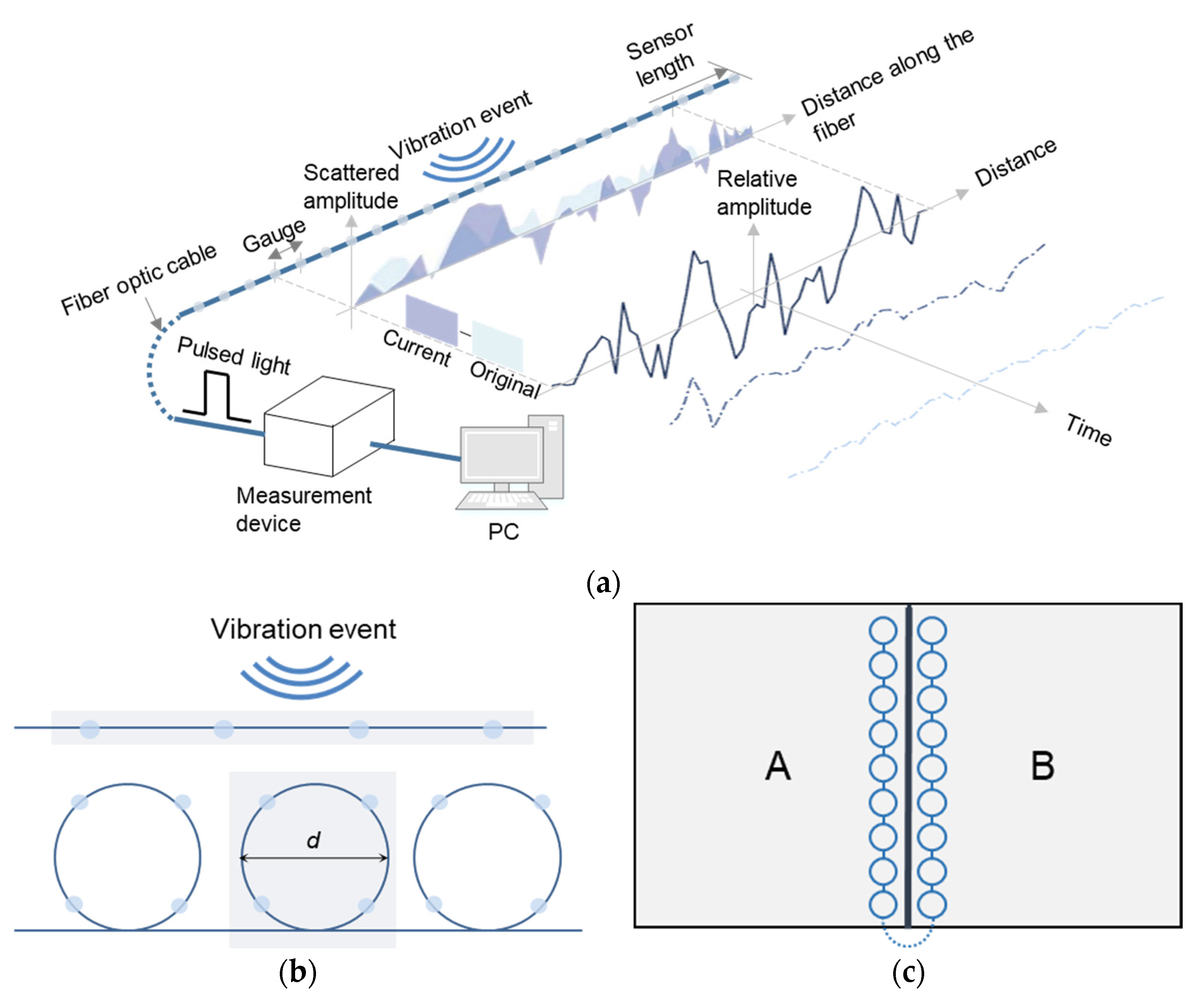
Distributed optical vibration sensors (DOVS) can measure vibration around joints distributedly. DOVS relies on the technology of phase optical time-domain reflection (φ-OTDR), which makes a single fiber optic cable become a multipoint sensor for measurement and localization. Figure 3a illustrates the schematic principle of φ-OTDR. A measurement device continuously emits pulse light at one end of the cable when measuring. The light waves reflect the signal to the device along the cable. When a vibration event disturbs the cable, the cable’s mechanical properties will influence the scattered amplitude of the reflected light. The relative amplitude of the reflected light is analyzed for vibration information, while the position information is analyzed according to the time difference of each reflected light. Therefore, DOVS can measure vibrations along the fiber optic cable continuously and distributedly.
The sampling frequency of a commercial DOVS measurement device can reach 2500 Hz but the spatial resolution is usually more than 2 m. It is not precise enough to locate vibrations in concrete pavement. Zeng et al. [31] proposed a design of vibration monitoring units based on looped fiber optic cables, as shown in Figure 3b. The length of the cable is 4 m in each monitoring unit (looped four times with a 0.3 m diameter). The designed monitoring unit has more than one measurement point to improve the accuracy of measurement. Also, the measurement can mostly represent the vibration information located on the thirty-centimeter-diameter monitoring unit, which improves the localization precision compared with a four-meter section of a linear cable.
Therefore, as shown in Figure 3c several monitoring units can be arranged on both sides of a joint to measure the vibration around the joint at the same time.

2.3. Calculation for the Ratio of Vibration Amplitude

The original DOVS data is recorded in time history and contains noises, bringing difficulties to capture the accurate amplitudes of vibration at different frequencies. Qin et al. [33] and Du et al. [34] proposed some wavelet-based denoising methods which are widely used for vibration measurement in concrete pavement. Thus, the first step is to denoise the original DOVS data.
  • Denoise the original DOVS data:
W f ( b , 2 j ) = x 1 ( t ) 1 2 j φ t b 2 j d t
where x1(t) denotes the normalized signal in time history, Wf(b, 2j) denotes the jth wavelet coefficient, and φ denotes the function of the wavelet base (Daubechies 4). Soft -thresholding denoising is applied to obtain the wavelet coefficients:
w λ = s i g n ( w ) ( w λ ) , w λ 0 w < λ
where wλ denotes the wavelet coefficient after the soft-thresholding denoising, w denotes the original wavelet coefficient, and λ denotes the threshold value. The original and denoised data is shown in Figure 4a.
2.
Calculate the PSD of measurement point i:
Zhao et al. [29] indicated that power spectral density (PSD) can describe the amplitude of concrete pavement vibration along the frequency domain. Therefore, the ratio of vibration response around a joint can be calculated by the following steps:
P S D i f = 1 Δ f lim T 1 T 0 T x i t , f , Δ f x i t , f , Δ f d t
where xi(t) denotes the denoised data of measurement point i, f denotes frequency. Figure 4b shows three examples from different measurement points. In Figure 4b, it is easier to observe the vibration amplitudes in the frequency domain rather than in the time domain.
3.
Combine the PSD of all measurement points around the joint:
P S D = P S D 1 f l P S D 1 f h   P S D n s f l P S D n s f h  
where fl and fh denote the lower and upper limits of the frequency band. Figure 4c illustrates an example of combined PSD. Compared with the PSD from a single measurement point, the combined PSD provides information about how vibration amplitudes vary in the spatial domain and also gives a global view to find the natural frequencies.
4.
Extract the vector of PSD at mth natural frequency and divide it into two sets:
P S D A f m = P S D 1 f m ,   P S D 2 f m P S D i f m T n s = 1 ,   2 i S A
P S D B f m = P S D i + 1 f m ,   P S D i + 2 f m P S D j f m n s = i + 1 ,   i + 2 j S B
where SA, SB denotes the measurement points on Slab A and Slab B respectively.
5.
Calculate the ratio of PSDA(fm) and PSDB(fm):
R P S D AB f m = P S D A f m P S D B f m = P S D 1 f m P S D i + 1 f m P S D 1 f m P S D i + 2 f m P S D 1 f m P S D j f m P S D 2 f m P S D i + 1 f m P S D 2 f m P S D i + 2 f m P S D 2 f m P S D j f m P S D i f m P S D i + 1 f m P S D i f m P S D i + 2 f m P S D i f m P S D j f m
6.
Estimate the density distribution of elements in RPSDAB(fm) by kernel density estimation (KDE). The estimated probability density of RPSD at frequency f is calculated as:
K D E f = b i K b f s i
where bi is the weighting of each point with ∑bi = 1. Kb(x) is the zero-centered Gaussian kernel function with bandwidth b and is given by:
K b f s i = 1 2 π b e 1 2 f s i b 2
where si denotes the value of sample i in RPSDAB(fm).
Figure 4d shows an example of the estimated density distribution. The maximum of 0.389 means most elements of RPSDAB(fm) are located around 0.389. The maximum can be regarded as the representative value that reflects RPSDAB(fm) in global.

3. Field Testing

Field testing was conducted to validate the vibration-based monitoring method. The conventional deflection-based method as well as the proposed vibration-based method were applied to assess LTE at different joints. A comparative analysis was employed to validate the accuracy of the vibration-based method.

3.1. Test Set-Up

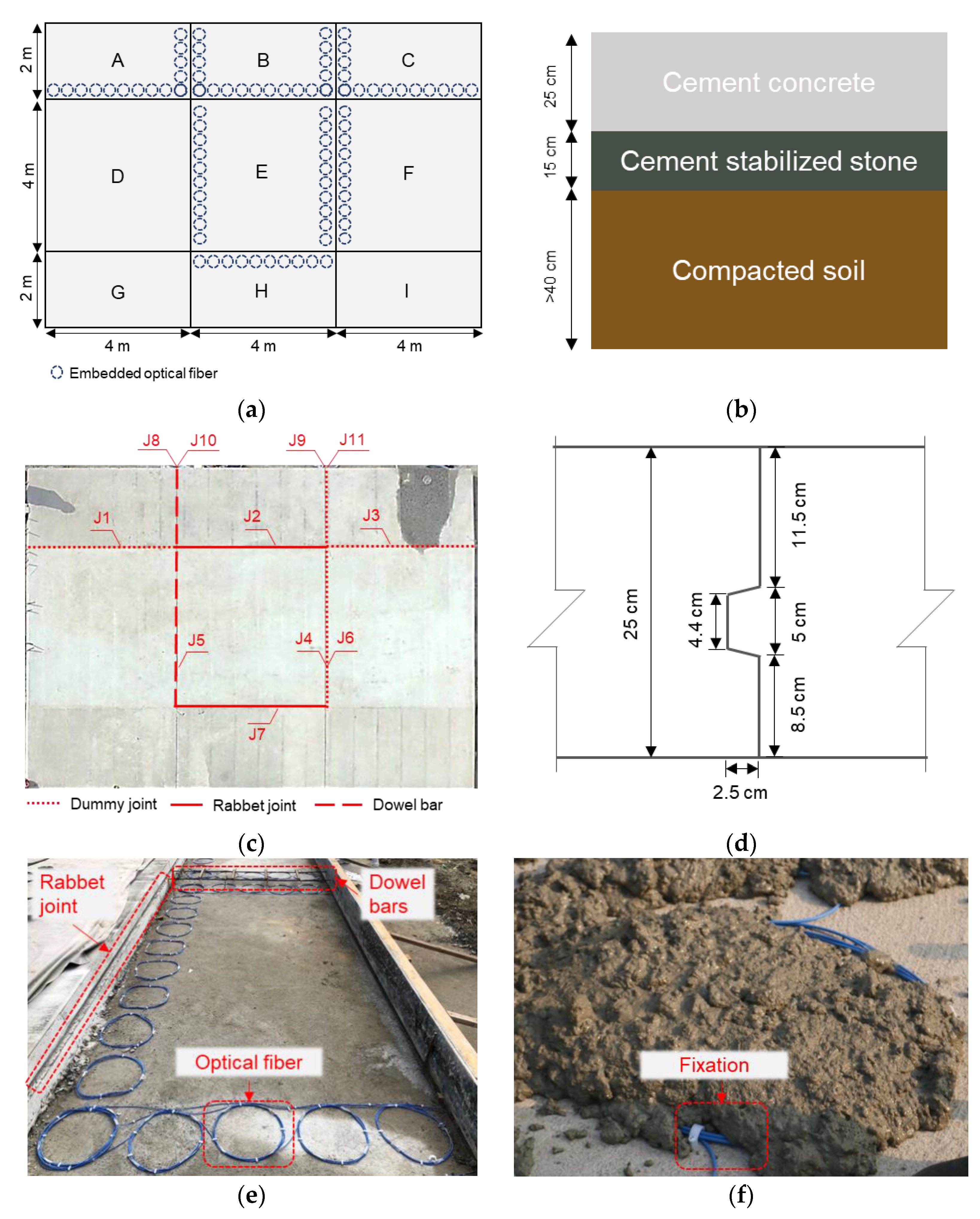
A test site consisting of nine concrete pavement slabs was constructed at Tongji University. The thickness of the nine slabs was all 25 cm. Figure 5a depicts the length and width of the nine slabs. As shown in Figure 5b, the thickness was 15 cm of the cement stabilized base. The subgrade was made of compacted soil and was more than 40 cm thick. The grade of the concrete was C45. Its flexural strength was 4.9 MPa (28 day). The concrete was produced and provided by a commercial company (Shanghai Chengjian Group).
There were eleven scenarios set for the field testing, as shown in Figure 5c. Note that some scenarios (e.g., J4 and J6) were located at the same joint but the LTE was assessed from different directions, so they were considered as two different scenarios.
Three kinds of joints (dummy joint, rabbet joint, and dowel bars) were constructed in the field testing. The cross-section of the rabbet joint is shown in Figure 5d. The dowel bars were 50 cm in length, 2.5 cm in diameter, and arranged with a forty-centimeters gap. The dummy joint was 10 cm in depth and 0.3 cm in width.
A vibration sensing system was developed based on DOVS in field testing. Monitoring units were embedded into the concrete pavement slabs to measure their vibrations. There were ten monitoring units arranged along a four-meter-long joint while five monitoring units along a two-meter-long joint. The monitoring unit’s diameter was 30 cm.
As shown in Figure 5e,f, the monitoring units were fixed on the base before concrete placing to maintain the optical sensors in the right place. During concrete placing, some concrete was firstly placed around the optical sensors to provide support to keep the optical sensors in right place.

3.2. Data Collection

A falling weight deflectometer (FWD) was employed to apply impulse load and measure the deflections of concrete pavement slabs. The impulse load was produced by dropping a large weight onto a buffer which shapes the pulse and then transmitted to the pavement through a circular load plate. Then pavement’s deflections were measured by nine displacement sensors, as shown in Figure 6a.
To assess the deflection-based LTE of a joint, the second and third displacement sensors were set symmetrically against the joint, as shown in Figure 6b,c. The deflection-based LTE of the joint could be calculated as:
L T E =   w a w l
where wa, wl denotes the measured deflections on the adjoining unloaded slab and the loaded slab respectively.
In the field testing, the impulse load was applied to different joints. For each joint, the weight was dropped from three different heights, which produced impulse loads at three levels (80, 100, and 120 kN). The measurement was repeated three times for each load level, so there were nine measurements of deflections. Meanwhile, the DOVS-based vibration sensing system measured the vibration around joints. The corresponding RPSD was calculated according to Equations (17)–(25).
The above procedures were conducted twice. The first time was in July 2020 (ambient temperature was 31 °C) and the second time was in November 2020 (ambient temperature was 13.6 °C). Thus there were two test series to have a better comparison between deflection-based LTE and RPSD.

3.3. Results of Deflection-Based LTE (DLTE)

Table 1 shows the measurement results of deflection-based LTE (DLTE) in the two tests. Figure 7 compares the DLTE measured on different dates and joints. It is found that the DLTE of J4 was 0.814 and 0.688 in July 2020 and November 2020 respectively. Both the DLTEs were positive but the decrease was about by 18.31%. Similarly, the DLTE of J8, J9, and J11 decreased by about 15.57 to 32.25% in the second test, but the other joints’ DLTE vary more slightly (decreased by 9.28% or increased by 2.47% in maximum). Considering these joints are mostly dummy joints and the second test was conducted in winter, the decrement of their DLTE should be due to the slab movements caused by temperature, because the width of dummy joints increases at a lower temperature, as a result of slab movements, which results in significant deterioration of DLTE.
Also, there are some deviations among the nine measurements at the same joint, which are between 0.002~0.05. These deviations are due to the measurement error from FWD (whose accuracy is ±2 μm according to its specification). Since the DLTE is a ratio of measured deflections, the influence of measurement error becomes more significant after the division between two measurements.

3.4. Results of the Ratio of Power Spectral Density (RPSD)

From Equations (19)–(25), the estimation of RPSD is related to how many natural frequencies are considered during the calculation. Figure 8 shows an example of the estimated density distribution when considering different numbers of natural frequencies. For example, Num = 10 means that the first ten orders of natural frequencies are considered to calculate and estimate the density distribution.
From Figure 8, it is found that the more natural frequencies is considered, the lower deviation of the estimated density distribution is, as well as the more stable the maximum will be. This is due to the different numbers of samples for density estimation. Measurement errors will influence the estimation results easily if there are only a few samples. If more natural frequencies are considered, more samples will come into the estimation and can reduce the influence of measurement errors.
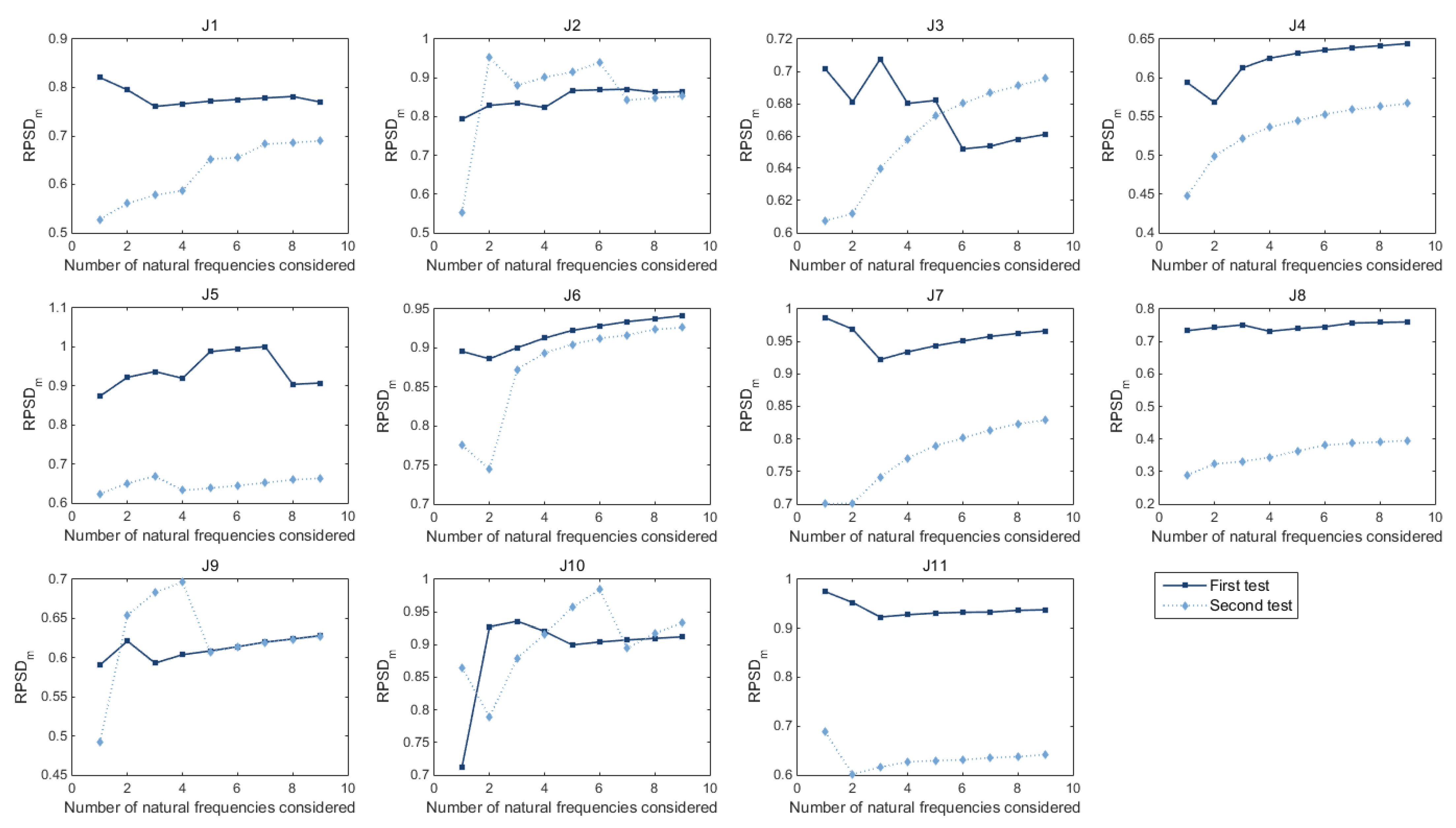
However, more samples bring a heavier burden of calculation. Figure 9 illustrates the calculated RPSD maximum (RPSDm) of different joints when different numbers of natural frequencies are considered. It is found that the calculation results fluctuate a lot when considering less than four natural frequencies and become stable when more than eight natural frequencies are considered. This phenomenon exists in most joints and both two tests, which proves the influence of natural frequency. Therefore, to find a balance between accuracy and effectiveness, the first nine natural frequencies were selected to calculate RPSDm.
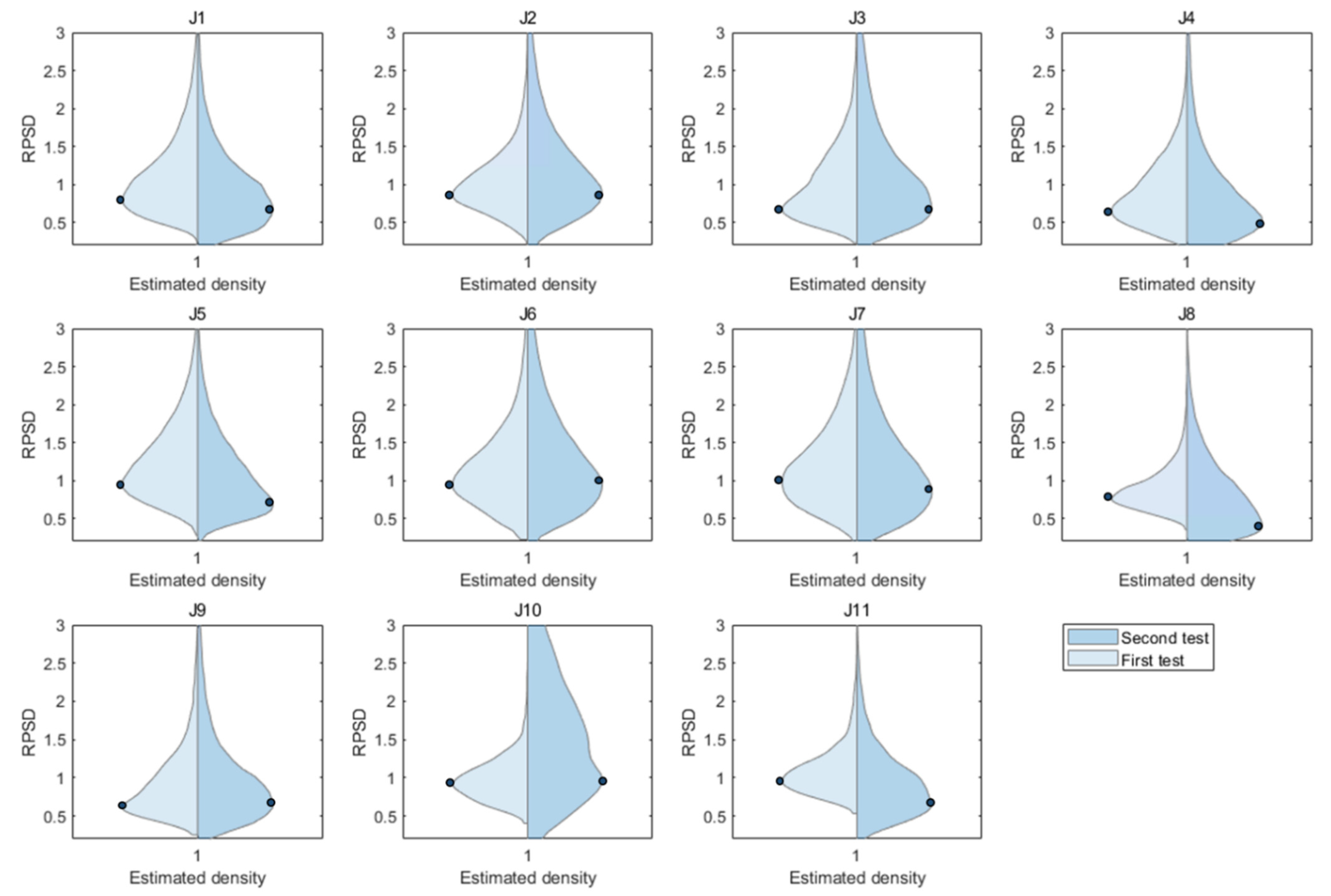
Figure 10 illustrates the estimated density distribution of RPSD from different joints. Each subfigure shows the results of two tests. The left side is the first test, and the right side is the second test. The maximum of the RPSD’s density distribution is marked by dark blue points. It is found that:
(1) There is a shift in the maximum of RPSD’s density distribution in J1, J4, J5, J8, J9, and J11. The deflection-based LTE (DLTE) of these six joints also changes by more than 5% according to Table 1. It suggests the maximum density distribution, as the representative value of RPSD estimation, can reflect the change in DLTE sensitively.
(2) J8 and J10 just have a slight change in DLTE, as well as the maximum of RPSD’s density distribution. However, their deviation of RPSD changes a lot. This is because that the deterioration of the joint is usually caused by local damage or defects. After deterioration, the load transfer efficiency is not the same along the length of the joint.

3.5. Discussion of the Correlation between DLTE and RPSD

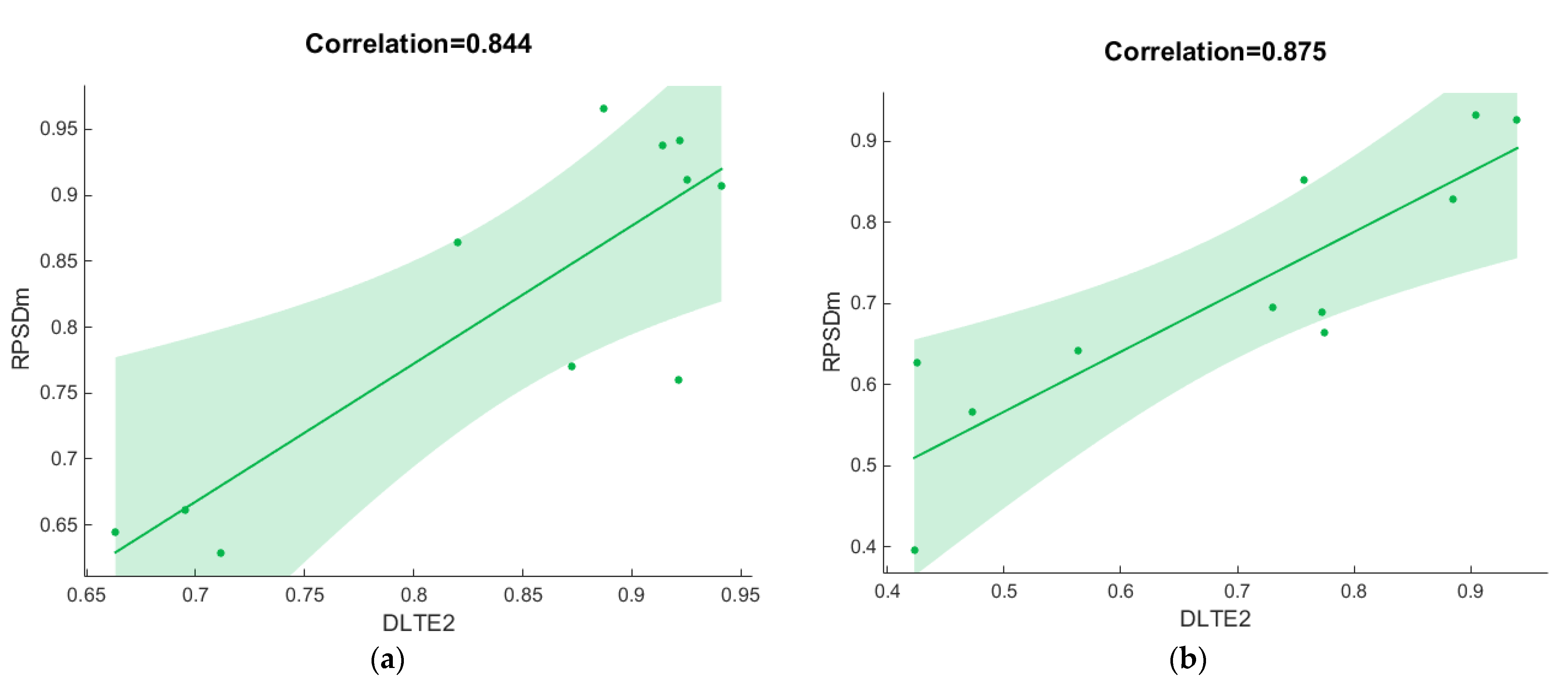
To further investigate the correlation between DLTE and RPSD, the maximum of RPSD’s density distribution (denoted by RPSDm) was extracted from each subfigure of Figure 10 and compared with the corresponding DLTE from Table 1. Figure 11 shows their correlation in the two tests. Note that DLTE squared (DLTE2) is utilized for comparison in Figure 11 because PSD’s amplitude is the frequency spectrum’s amplitude squared. The green area is the 95% confidence interval, which means that there is a 95% probability that the true best-fit line for the populations lies within the confidence interval. From Figure 11, it is found that:
(1) In the first test, the DLTE2 is between 0.65~0.95 and mainly concentrated around 0.90. The correlation between RPSDm and DLTE2 is about 0.844.
(2) In the second test, some joints’ condition deteriorate significantly so the range of DLTE2 become wider (0.40~0.95). But the correlation is still 0.875.
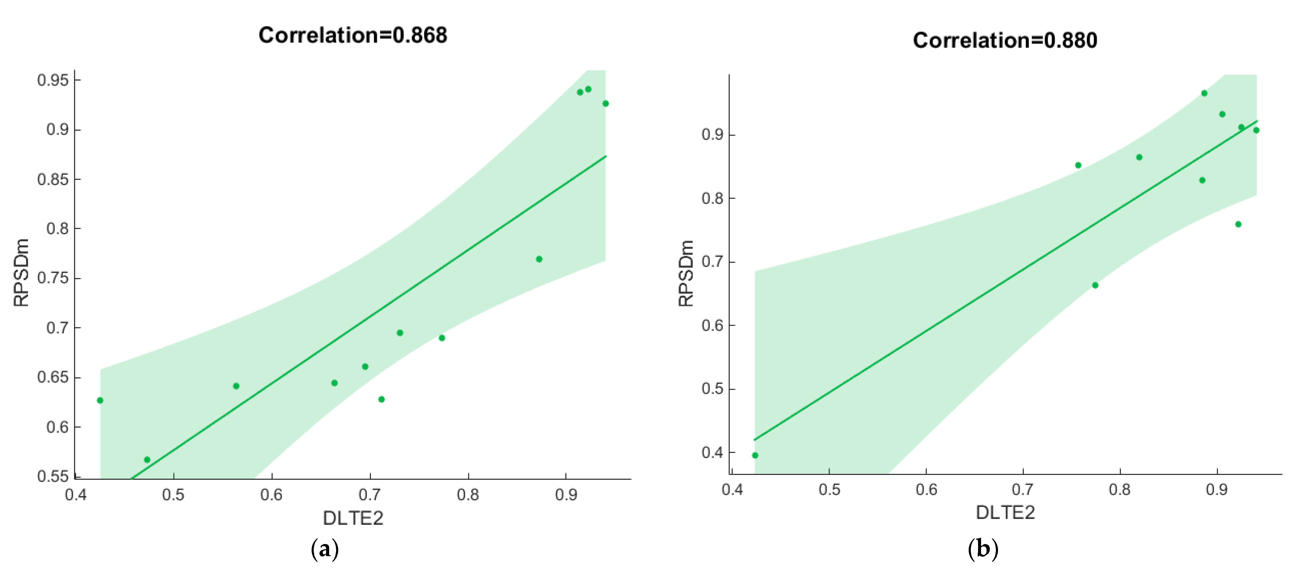
Similarly, Figure 12 illustrates the correlation between RPSDm and DLTE2 in different types of joints. Figure 12a shows the results of dummy joints. Since the samples of rabbet joints and dowel bars are both much fewer than dummy joints, their results are illustrated together in Figure 12b. It is found that:
(1) Owing to the sensitivity to temperature, the DLTE2 of dummy joints is distributed between 0.40~0.95 and has more deviations than other types of joints. The correlation is 0.868.
(2) The DLTE2 of rabbet joint and dowel bars are mostly concentrated in 0.75~0.90 as the temperature has a slight influence on their DLTE2. The correlation is around 0.880.
From Figure 11 and Figure 12, the findings indicate that RPSDm has a significant correlation with DLTE2. The correlation is close in different types of joints as well as two different tests that have a four-month gap. It proves the robustness of the vibration-based method.
Besides, to investigate the accuracy of the RPSDm, Figure 13a illustrates the correlation between RPSDm and DLTE2 according to the all results of the two tests. Also, the difference between RPSDm and DLTE2 (ΔRL)is calculated as
Δ R L = R P S D m D L T E
and its cumulative distribution is shown in Figure 13b.
From Figure 13, It is found that: (1) the overall correlation between RPSD and LTE is 0.880. It is very close to the results in Figure 11 and Figure 12. (2) the 5% and 95% percentile of ΔRL is about −0.08 and 0.06, respectively, which means 90% of ΔRL is between −0.08~0.06. The main part of the difference is due to DLTE. According to reference [7,8,9], the measured deviation of DLTE could usually reach 0.042. It agrees with the measurement results shown in Table 1. The deviation reaches 0.050 from Table 1. Therefore, the ΔRL should be mostly below ±0.03 regardless of the DLTE-part error. It also agrees with the test results in reference [12], from which the difference is about ±0.02.

4. Conclusions

This paper presents a novel method to assess the load transfer efficiency (LTE) of concrete pavement joints using distributed optical vibration sensors. According to the contribution to the knowledge, contribution to the practice, and the limitation of the current study, the conclusions are as follows:
(1)
Through theoretical analysis of vibration on the loaded and unloaded slab, the LTE of joints can be reflected by the ratio of power spectral density (RPSD) at natural frequencies. The field test results also indicate that LTE and RPSD have a strong correlation (0.871) and a slight difference (< ±0.03) overall, which proves the accuracy and effectiveness of the vibration-based method.
(2)
Distributed optical vibration sensor (DOVS) can measure the vibration around concrete pavement joints distributedly, which is beneficial for the precision of RPSD in practical measurement. According to the field test results, the correlation between LTE and RPSD is robust in different dates and types of joints (0.844~0.880), which proves the robustness of the vibration-based method in practical applications.
(3)
Future work will be made to apply this method under traffic loads. It is much more convenient to utilize traffic loads as excitation rather than impulse loads provided by a specific device. With traffic loads from passing by vehicles, LTE can be assessed and monitored continuously and in real time.

Author Contributions

Conceptualization, M.Z. and D.W.; methodology, M.Z. and H.Z.; software, M.Z.; validation, Z.B. and K.P.; writing—original draft preparation, M.Z. and H.Z.; writing—review and editing, Z.B. and D.W.; supervision, H.Z.; project administration, H.Z.; funding acquisition, H.Z. and D.W. All authors have read and agreed to the published version of the manuscript.

Funding

This research was funded by the National Natural Science Foundation of China (grant numbers: 51978520 and 52008309).

Institutional Review Board Statement

Not applicable.

Informed Consent Statement

Not applicable.

Data Availability Statement

Not applicable.

Conflicts of Interest

The authors declare no conflict of interest.

References

  1. César, A.; Pradena, M. Sustainable engineering: Load transfer characterization for the structural design of thinner concrete pavements. Sustainability 2020, 12, 9153. [Google Scholar] [CrossRef]
  2. Khazanovich, L.; Gotlif, A. Evaluation of PCC joint stiffnesses using LTPP data. In Proceedings of the 8th International Conference on Concrete Pavements: Innovations for Concrete Pavement: Technology Transfer for the Next Generation, Colorado Springs, CO, USA, 18 August 2005; pp. 1120–1137. [Google Scholar]
  3. Lin, W.; Dong, Y.; Jung, Y.; Zheng, H.; Cho, Y.H. Performance evaluation of bedding sand and load transfer characteristic of concrete block pavements. Appl. Sci. 2021, 11, 10111. [Google Scholar] [CrossRef]
  4. Wadkar, A.; Mehta, Y.; Cleary, D.; Guo, E.; Musumeci, L.; Zapata, A.; Kettleson, W. Load-transfer efficiencies of rigid airfield pavement joints based on stresses and deflections. J. Mater. Civ. Eng. 2011, 23, 1171–1180. [Google Scholar] [CrossRef]
  5. Mackiewicz, P. Analysis of stresses in concrete pavement under a dowel according to its diameter and load transfer efficiency. Can. J. Civ. Eng. 2015, 42, 845–853. [Google Scholar] [CrossRef]
  6. Guo, H.; Petch, F.; Ricalde, L. Analysis of concrete pavement strain data and behaviour during joint formation. Int. J. Pavement Eng. 2010, 11, 173–187. [Google Scholar] [CrossRef]
  7. Khafajeh, R.; Shamsaei, M.; Tehrani, H.G.; Easa, S.M. Proposing load transfer efficiency as criterion for repairing longitudinal and transverse cracks of asphalt pavements. J. Transp. Eng. Part B Pavements 2021, 147, 06021002. [Google Scholar] [CrossRef]
  8. Zhang, Y.C.; Gao, L.L. Effect of dowel bar position deviation on joint load-transfer ability of cement concrete pavement. Int. J. Pavement Res. Technol. 2016, 9, 30–36. [Google Scholar] [CrossRef]
  9. Sok, T.; Hong, S.J.; Kim, Y.K.; Lee, S.W. Evaluation of load transfer characteristics in roller-compacted concrete pavement. Int. J. Pavement Eng. 2020, 21, 796–804. [Google Scholar] [CrossRef]
  10. Guo, E.H. Back-estimation of slab curling and joint stiffness. In Proceedings of the Seventh International Conference on Concrete Pavements: The Use of Concrete in Developing Long-Lasting Pavement Solutions for the 21st Century, Orlando, FL, USA, 13 September 2001. [Google Scholar]
  11. Cunliffe, C.; Joshi, A.; Mehta, Y.; Cleary, D. A study to determine the impact of cracking on load transfer efficiency of rigid airfield pavements. J. Test. Eval. 2014, 42, 375–389. [Google Scholar] [CrossRef]
  12. Zhang, X.; Liu, X.; Zhang, Z. Rigid pavement load transfer ability of airport based on vibration characteristics. J. Beijing Univ. Aeronaut. Astronaut. 2018, 44, 1787–1796. [Google Scholar]
  13. Zhao, H.; Zeng, M.; Chen, H.; Ling, J.; Wu, D. Investigating the Effect of Prestress Force on Cross-Tensioned Concrete Pavement Vibration. Transp. Res. Rec. 2020, 2674, 875–886. [Google Scholar] [CrossRef]
  14. Wu, D.; Zeng, M.; Zhao, H.; Wang, Y.; Du, Y. Detection and localization of debonding beneath concrete pavement using transmissibility function analysis. Mech. Syst. Signal Processing 2021, 159, 107802. [Google Scholar] [CrossRef]
  15. Bao, X.; Chen, L. Recent progress in distributed fiber optic sensors. Sensors 2012, 12, 8601. [Google Scholar] [CrossRef]
  16. Zeng, M.; Chen, H.; Ling, J.; Zhao, H.; Wu, D. Monitoring of prestressing forces in cross-tensioned concrete pavements during construction and maintenance based on distributed optical fiber sensing. Autom. Constr. 2022, 142, 104526. [Google Scholar] [CrossRef]
  17. Monsberger, C.M.; Lienhart, W. Distributed fiber optic shape sensing of concrete structures. Sensors 2021, 21, 6098. [Google Scholar] [CrossRef] [PubMed]
  18. Diouf, B.M.; Che, A.; Feng, S. Study of a Space-Time Monitoring of High-Speed Railway Underline Structure Using Distributed Optical Vibration Sensing Technology. Shock. Vib. 2019, 2019, 9263259. [Google Scholar] [CrossRef]
  19. Lienhart, W.; Wiesmeyr, C.; Wagner, R.; Klug, F.; Litzenberger, M.; Maicz, D. Condition monitoring of railway tracks and vehicles using fibre optic sensing techniques. In Proceedings of the Transforming the Future of Infrastructure through Smarter Information: Proceedings of the International Conference on Smart Infrastructure and Construction, Cambridge, UK, 27–29 June 2016; pp. 45–50. [Google Scholar]
  20. Klug, F.; Lackner, S.; Lienhart, W. Monitoring of railway deformations using distributed fiber optic sensors. In Proceedings of the Joint International Symposium on Deformation Monitoring, Wien, Austria, 30 March 2016. [Google Scholar]
  21. Buchmayer, F.; Monsberger, C.M.; Lienhart, W. Advantages of tunnel monitoring using distributed fibre optic sensing. J. Appl. Geod. 2021, 15, 1–12. [Google Scholar] [CrossRef]
  22. Monsberger, C.M.; Lienhart, W. Distributed fiber optic shape sensing along shotcrete tunnel linings: Methodology, field applications, and monitoring results. J. Civ. Struct. Health Monit. 2021, 11, 337–350. [Google Scholar] [CrossRef]
  23. Monsberger, C.M.; Lienhart, W.; Kluckner, A.; Schubert, W. In-Situ assessment of distributed strain and curvature characteristics in shotcrete tunnel linings based on fiber optic strain sensing. In Proceedings of the 14th International Congress on Rock Mechanics and Rock Engineering, Foz do Iguassu, Brazil, 13–18 September 2019; pp. 1324–1331. [Google Scholar]
  24. Wang, X.; Shi, B.; Wei, G.; Chen, S.E.; Zhu, H.; Wang, T. Monitoring the behavior of segment joints in a shield tunnel using distributed fiber optic sensors. Struct. Control Health Monit. 2018, 25, 2056. [Google Scholar] [CrossRef]
  25. Zhang, W.; Gao, J.; Shi, B.; Cui, H.; Zhu, H. Health monitoring of rehabilitated concrete bridges using distributed optical fiber sensing. Comput. Aided Civ. Infrastruct. Eng. 2006, 21, 411–424. [Google Scholar] [CrossRef]
  26. Abdel-Jaber, H.; Glisic, B. Monitoring of prestressing forces in prestressed concrete structures—An overview. Struct. Control. Health Monit. 2019, 26, 2374. [Google Scholar] [CrossRef] [Green Version]
  27. Xiang, P.; Wang, H. Optical fibre-based sensors for distributed strain monitoring of asphalt pavements. Int. J. Pavement Eng. 2018, 19, 842–850. [Google Scholar] [CrossRef]
  28. Hauswirth, D.; Fischli, F.; Rabaiotti, C.; Puzrin, A.M. Distributed fiber optic strain measurements in an airfield pavement. In Proceedings of the 9th International Conference on Maintenance and Rehabilitation of Pavements-Mairepav9, Zurich, Switzerland, 1–3 July 2020; pp. 825–834. [Google Scholar]
  29. Zhao, H.; Wu, D.; Zeng, M.; Tian, Y.; Ling, J. Assessment of concrete pavement support conditions using distributed optical vibration sensing fiber and a neural network. Constr. Build. Mater. 2019, 216, 214–226. [Google Scholar] [CrossRef]
  30. Zhao, H.; Wu, D.; Zeng, M.; Zhong, S. A vibration-based vehicle classification system using distributed optical sensing technology. Transp. Res. Rec. 2018, 2672, 12–23. [Google Scholar] [CrossRef]
  31. Zeng, M.; Wu, D.; Zhao, H.; Chen, H.; Bian, Z. Novel assessment method for support conditions of concrete pavement under traffic loads using distributed optical sensing technology. Transp. Res. Rec. 2020, 2674, 42–56. [Google Scholar] [CrossRef]
  32. Zeng, M.; Zhao, H.; Wu, D.; Chen, H.; Cai, J. A vibration-based traffic monitoring system using distributed optical sensing technology. J. Test. Eval. 2019, 48, 1799–1813. [Google Scholar] [CrossRef]
  33. Qin, Z.; Chen, L.; Bao, X. Wavelet denoising method for improving detection performance of distributed vibration sensor. IEEE Photonics Technol. Lett. 2012, 24, 542–544. [Google Scholar] [CrossRef]
  34. Du, Y.; Weng, Z.; Li, F.; Ablat, G.; Wu, D.; Liu, C. A novel approach for pavement texture characterisation using 2D-wavelet decomposition. Int. J. Pavement Eng. 2022, 23, 1851–1866. [Google Scholar] [CrossRef]
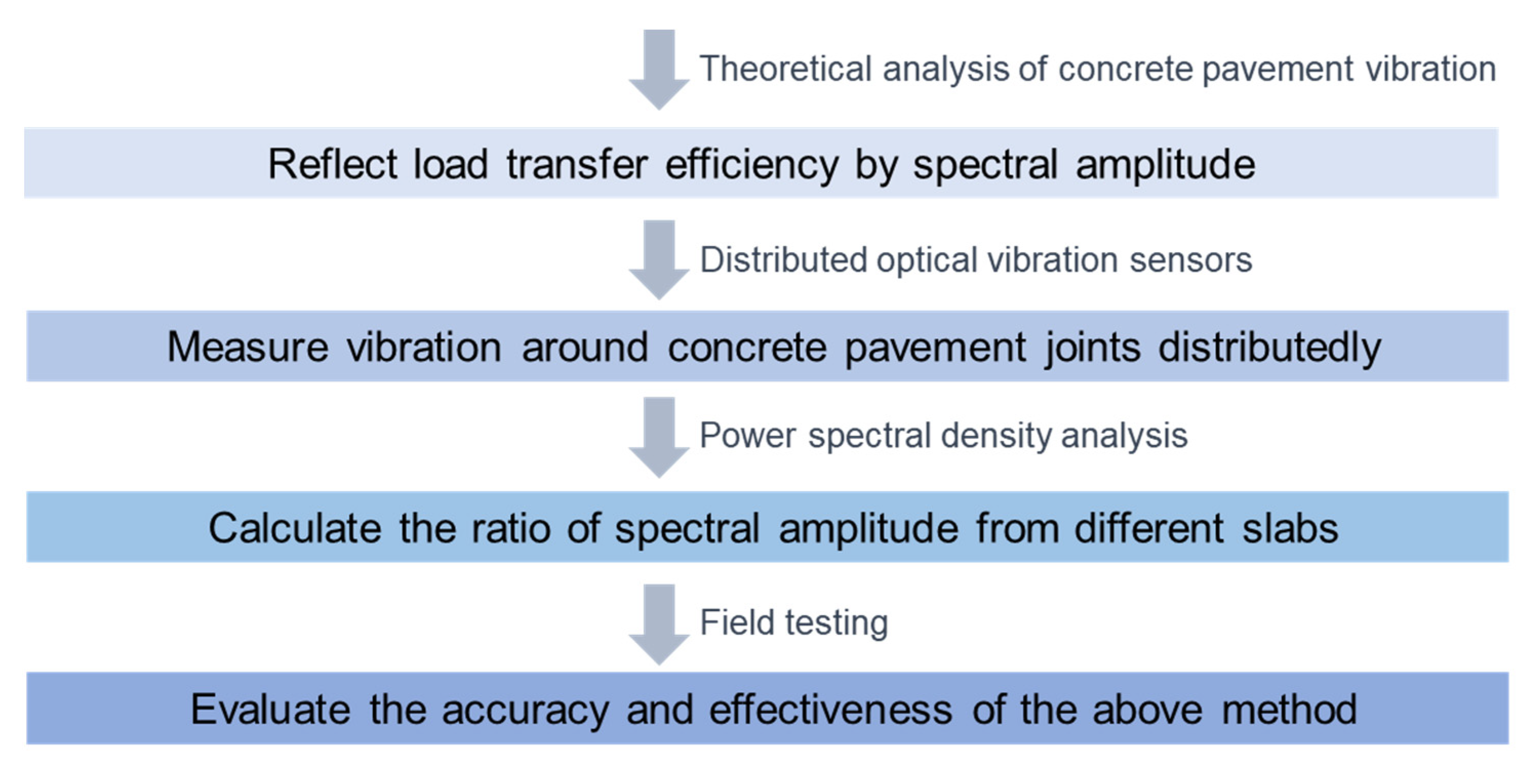
Figure 1. Phases of methodology.
Applsci 12 09273 g001
Figure 2. Impulse loads were applied on two concrete pavement slabs (plan view).
Applsci 12 09273 g002
Figure 3. Measurement of vibration around joints using distributed optical vibration sensors: (a) Schematic principle of phase optical time-domain reflection (φ-OTDR); (b) Design of monitoring unit; (c) Layout of the monitoring units when measuring vibration around a joint.
Applsci 12 09273 g003
Figure 4. Calculation procedures of vibration amplitudes: (a) Denoising; (b) Power spectral density analysis; (c) Power spectral density of different measurement points; (d) Kernel density estimation of RPSD.
Applsci 12 09273 g004
Figure 5. Field test set-up: (a) Dimension of the nine concrete pavement slabs; (b) Sectional view of the test site; (c) Scenarios of the joints; (d) Cross section of rabbet joint; (e) Vibration sensing system; (f) Maintain the sensors in the right position.
Applsci 12 09273 g005
Figure 6. Measurement of deflection-based LTE: (a) Falling weight deflectometer (FWD); (b) Details of FWD; (c) Layout of the nine displacement sensors.
Applsci 12 09273 g006
Figure 7. Measured deflection-based LTE of different joints on two dates.
Applsci 12 09273 g007
Figure 8. Estimated density distribution of RPSD considering different numbers of natural frequencies (J2, the second test).
Applsci 12 09273 g008
Figure 9. Calculated RPSDm of different joints considering different numbers of natural frequencies.
Applsci 12 09273 g009
Figure 10. Estimated density distribution of RPSD at different joints.
Applsci 12 09273 g010
Figure 11. Correlation between RPSDm and DLTE2 (a) In the first test; (b) In the second test.
Applsci 12 09273 g011
Figure 12. Correlation between RPSDm and DLTE2 (a) In dummy joints; (b) In rabbet joints and dowel bars.
Applsci 12 09273 g012
Figure 13. Comparative analysis between RPSDm and DLTE2 (a) Correlation; (b) Difference.
Applsci 12 09273 g013
Table 1. Measurement results of deflection-based LTE in the two tests.
Test SeriesNo. JointMeasurements of Deflection-Based LTEAverageDeviation
1#
July 2020
J10.9000.9300.9360.9370.9590.9400.9450.9290.9310.9340.015
J20.8820.8790.9150.8970.8960.8810.9310.9330.9360.9060.022
J30.8280.8380.8230.8380.8340.8140.8520.8400.8380.8340.010
J40.7620.7210.8660.8480.8820.8350.7780.8030.8350.8140.050
J50.9870.9650.9850.9150.9540.9900.9540.9631.0180.9700.028
J60.9530.9180.9090.9610.9871.0140.9460.9660.9880.9600.032
J70.9450.9290.9250.9360.9600.9330.9510.9490.9500.9420.011
J80.9610.9680.9560.9620.9680.9490.9590.9570.9600.9600.006
J90.8560.8520.8330.8660.8170.8440.8190.8440.8630.8440.017
J100.9670.9540.9770.9620.9480.9570.9730.9580.9620.9620.009
J110.9270.9030.9161.0000.9890.9630.9640.9720.9730.9560.031
2#
November 2020
J10.8790.8800.8800.8780.8770.8780.8810.8800.8800.8790.001
J20.8690.8700.8720.8720.8740.8710.8650.8680.8710.8700.003
J30.8600.8570.8530.8520.8470.8460.8610.8580.8560.8550.005
J40.6710.6720.6670.6950.6940.6900.7050.6980.6970.6880.013
J50.8760.8730.8740.8810.8840.8850.8810.8830.8840.8800.004
J60.9780.9770.9760.9640.9620.9620.9690.9690.9700.9700.006
J70.9420.9360.9370.9440.9370.9360.9440.9440.9450.9410.004
J80.6250.6180.6110.6490.6530.6510.6810.6850.6790.6500.026
J90.6400.6390.6360.6590.6530.6470.6690.6630.6620.6520.011
J100.9510.9520.9560.9540.9490.9480.9510.9490.9530.9510.002
J110.7520.7450.7410.7530.7430.7440.7650.7580.7550.7510.008
Publisher’s Note: MDPI stays neutral with regard to jurisdictional claims in published maps and institutional affiliations.